
Abstract
This paper presents an implementation framework to perform a vision-guided, bat-like inverted perching maneuver with a bi-directional thrust quadrotor platform. The framework consists of several distinct modules (guidance, motion planning, control, state estimation) that can be easily be individually customized in the future to meet specific research requirements. The main contribution of this paper lies in the whole framework pipeline with a modular structure developed for implementing a generalized framework for an agile quadrotor to achieve inverted perching. A computationally-light guidance module has been developed as an example to demonstrate the capability while being independent of accurate pre-known target information, and does not require the state estimation of the quadrotor to be provided by an external motion capture system as in our previous work. A motion planning module based on an optimization method has been introduced to generate a two-stage inverted perching trajectory aiming at minimizing altitude loss during the half-flip maneuver. A control module has been developed to enable a bi-directional quadrotor to fly in both upright and inverted states and closely follow the intended trajectory. The compensation strategy used in the control module is key to minimizing the transition time between the upright and inverted states. Finally, an experimental flight platform has been developed to demonstrate the capabilities of the framework. During testing, the proposed framework has achieved an 80 % success rate. To the best of our knowledge, this paper presents the first time a quadrotor has achieved the inverted perching maneuver using onboard vision guidance.
Keywords
Introduction
Unlike most birds, bats perch and hang upside-down. Hanging upside down has the benefit of being statically stable but the ability to achieve inverted perching has not yet been demonstrated on a UAV (Unmanned Aerial Vehicle). This paper presents a framework for performing such an inverted perching maneuver using a bi-directional thrust quadrotor, mimicking the way bats perch in nature. The new “perch and watch” capability for a quadrotor can be highly beneficial to missions that require extended observation-time on-station, such as monitoring wild life in a natural reserve. This inverted perching capability can also avoid the downwash effect that is commonly encountered during a traditional, upright perching maneuver. The downwash may be blocked by the perching target, generating disturbances in the flow entering the propeller disks. This phenomena is similar to a helicopter landing on a ship and is discussed in literature such as. 1 To mimic this bat-like maneuver, a bi-directional thrust quadrotor has been proposed. The flight envelope of a quadrotor is easily doubled with bi-directional thrust using simple fixed-pitch propellers which can be reversed to achieve stable flight in either upright or inverted modes. This set up is mechanically much more simple than the variable pitch mechanisms commonly used in other rotary wing aircraft. The ability to fly in both upright and inverted orientations is one potential advantage that aircraft could have over birds.
Additional benefits gained from the ability to achieve both upright and inverted flight include the ability to carry two different payloads separately on the top and the bottom of the flight platform. The quadrotor could switch payloads with a simple half flip maneuver. With a more versatile manipulator end-effector, the current platform could be extended to more complicated tasks, such as aerial grasping, capturing, and assembling. redThere are two advantages in adopting a bi-directional thrust quadrotor with a downward manipulator rather than the traditional upward gripper. Firstly, the bi-directional thrust quadrotor still keeps the capability of perching or grasping the target which is located underneath the flying platform. Secondly, it also does not require a separate set of landing gear (as would be in the case of gripper on top of the platform) as the vehicle can be inverted and the downward manipulator can function as the landing gear.
The proposed framework architecture is designed to be modular, with onboard self-contained guidance, motion planning, control and state estimation modules, allowing future research in different fields to easily customise the corresponding modules within. For example, researchers studying manipulation can improve upon the force/position controller for aerial manipulation, while researchers in computer vision can improve upon the detection and vision guidance algorithm. Both upgraded algorithms could then be implemented into the same configuration (as described in this paper) without necessitating significant changes in the other modules.
This work improves upon our previous work 2 by removing the limitation of relying on accurate pre-known target information and state estimation of the quadrotor provided by an external motion capture system with the proposed onboard, computational-light guidance module. A Quadratic Programming (QP) based optimization motion planning module has been introduced to generate a two-stage upside-down perching trajectory aimed at minimizing altitude loss during the half-flip maneuver. A control module has been developed to enable a bi-directional thrust quadrotor to achieve stable upright and inverted flight states and closely follow an intended flight trajectory. The compensation strategy used in the control module is key to minimizing the transition time between the upright and inverted states. Finally, an experimental flight platform has been developed to demonstrate the capabilities of the perching algorithm. With the proposed implementation framework, an 80 % success rate has been achieved. To the best of our knowledge, this work is the first example of a quadrotor successfully perching upside-down using onboard vision guidance.
Related Work
Bi-Directional Thrust
Multirotors that utilize bi-direction thrust with fixed-pitch mechanisms have previously been explored in works proposed by Maier 3 and Jothiraj 4 . Experiments have been completed both indoors (with a motion capture system) and outdoors (with GPS). While both papers remark on the dead zone when reversing the propeller directions, no attempts were made to compensate for this adverse behavior. Furthermore, the phenomenon of the thrust differences when reversing the propellers were not explored, which can result in as much as a 15 % thrust difference at the same power setting due to the absence of the downwash obstructions on the frame.5,6 Hence, some form of compensation method should be added to achieve more accurate flight control.
Vision Guidance
Locating and tracking the target perching location (or target object) to be manipulated is a crucial aspect of any aerial perching/gasping maneuver . Vision guidance algorithms can be based on color detection,7,8 feature detection9,10, and machine learning. Cutting-edge methods such as R-CNN series11–13 and YOLO 14 have surpassed classical detection methods. However, these methods rely on high-performance computational resources for pre-training. A simple color detection with detected distance can be sufficient to fulfill aerial perching or grasping tasks. Position-based vision control (PBVS) and image-based vision control (IBVS) are two fundamental approaches for visual servoing and are discussed in detail by other researchers.15,16
For techniques such as IBVS, Thomas 17 used a quadrotor equipped with a 1-DOF manipulator to mimic a hawk catching a fish at high-speed, although the work was limited to the longitudinal plane and the target needs to be of a prescribed color. A virtual image plane was introduced to map the location of the platform with image features. With a similar approach, Thomas 18 extended their work to demonstrate a quadrotor perching on a known cylindrical target (like a pole) with an upward camera and gripper in 3D space. Ramon 19 achieved an outdoor visual grasping with dual aerial manipulators. The developed system used an artificial neural network (ANN) to obtain the object’s position, then inferred the pose of the target using an alignment algorithm, which was filtered with an extended Kalman filter. Researchers developed a velocity controller using the image moment on the basis of the dynamic model of the entire system. Seo 20 formulated a stochastic model-predictive control framework to grasp a cylindrical target by ensuring the target was kept in the camera field of view while minimizing tracking error and control inputs. Since the IBVS method is usually developed directly onto the image plane, it is considered more robust.
Using PBVS, Ramon-Soria 21 achieved autonomous quadrotor landings on a pipe with a soft gripper and an RGBD camera. The pipe was detected with a trained neural network and the controller uses PBVS. Garimella 22 developed a nonlinear model predictive control (NMPC) controller to achieve visual grasping of a bottle with the aid of active LED arrays. The controller was not running in real-time due to high computational cost, thus a high-frequency nonlinear position controller was also used in parallel. Shimahara 23 developed a quadrotor platform with an upward gripper on top to unscrew a light bulb. The target light bulb was detected with a monocular camera and analyzed with an onboard FPGA board with a specialized vision method. A torsional controller was used instead of a position controller. In general, most PBVS methods essentially recover pose from the projection of a known structure, which is well studied problem in computer vision. Since PBVS methods also work in 3D space, some other well developed methods used in other MAV literature24,25 can also be used.
General Aerial Perching and Grasping Implementation Framework
Overview
Unless specified otherwise, the nomenclature used in this paper is outlined in table 1.
Figure 1 presents the high-level block diagram for the proposed aerial perching framework. The first step in the architecture is to define the perching or grasping target. Then, the system takes in Additional Information from sources such as videos from cameras, data from the onboard lidars, a pre-built map or a pre-trained neural network. This information is then used by the Guidance module to identify and locate the target. The Guidance module generates desired waypoints to reach the target based on current estimated states and potential obstacles. The Motion Planning module generates a smooth trajectory input from the desired waypoints, which is then passed to the Control module. The Control module tracks the desired trajectory, and operates the servos driving the manipulators as required. The Control module sends the desired thrust and desired moments for controlling the aerial platform, and desired servo angle for manipulators. Thus, the whole Plant (the quadrotor with the manipulator) can interact with the target and the environment. The State Estimation module generates the optimal state estimate from sensor feedback, which is then passed back to the other modules. In addition to sensors onboard the flight platform, the state estimate can be augmented with information provided by external motion capture systems, additional IMUs, and VIO (Visual Inertial Odometry).
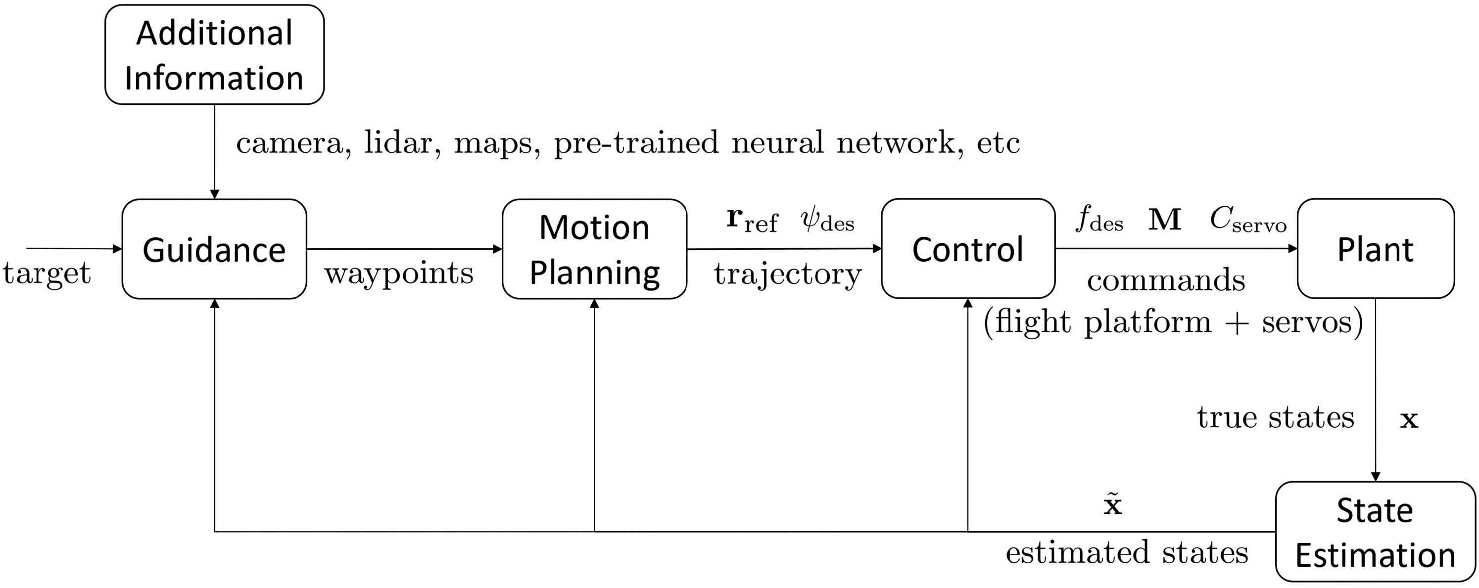
General Implementation Framework for Aerial Perching and Grasping, from Target Detection and Localization to Motion Planning and Execution on the Vehicle.
Nomenclature

This paper is organized as follows: the Control and Motion Planning modules are introduced first as they are closely connected. Then, the Guidance modules and Plant modules are explained in detail. Finally, the results of experimental testing are introduced, verifying the proposed framework.
Control Structure Overview
The manipulator developed for this work is light-weight and symmetric. The manipulator was designed to be symmetric as to minimize the effects of the manipulator on the parent quadrotor. Therefore, the movements of the manipulator can be treated as a disturbance force into the quadrotor model.
The standard forward-left-up reference coordinate system is shown in figure 2. The world frame

Body, World and Intermediate Coordinates used in this Work. The system follows the standard forward-left-up, right-hand axes convention.
The controller is split into two main components – the high-level controller (for position and attitude control), and the low-level controller (for rate control and motor mixing), as shown in figure 3. The low-level controller runs on a separate real-time computer to ensure accurate output timings and fast rate stabilization loop rates, regardless of the computational load generated by the high-level controller (outlined in more detail in Section Hardware System Overview).
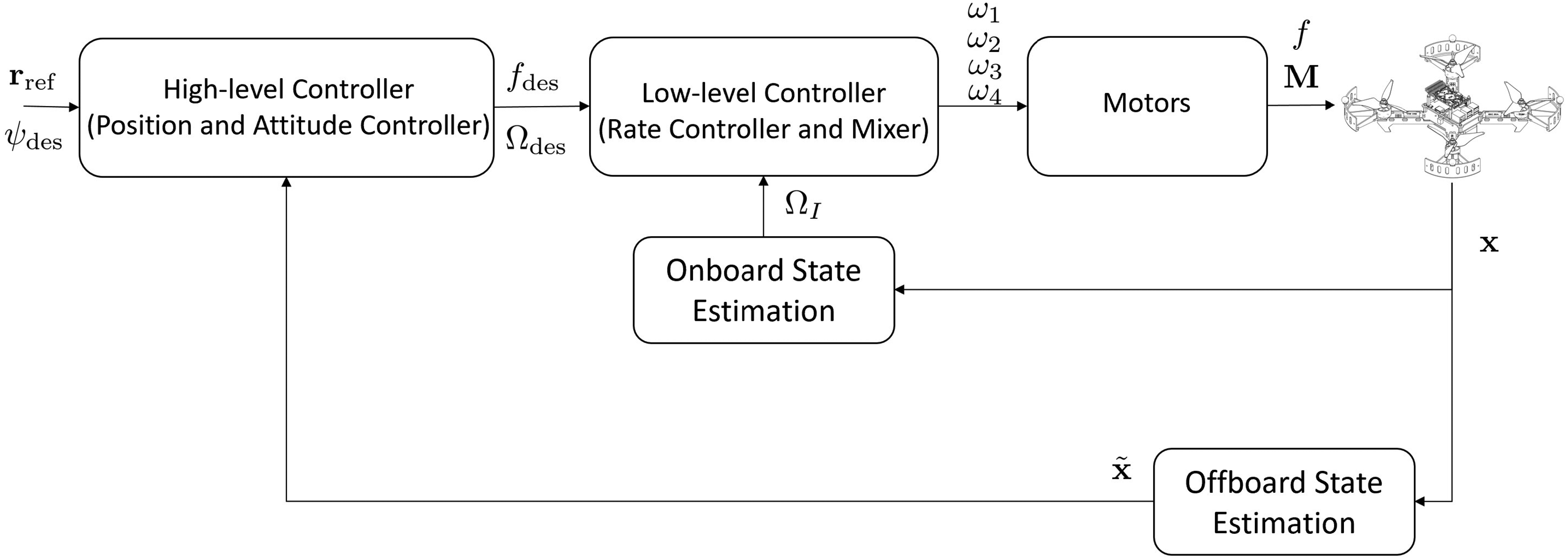
Control Structure Outlining the Interactions Between the High-Level and Low-Level Controllers, the State Estimation, and the Vehicle.
Position Controller
The desired acceleration 
The feed-back component, 
Based on the desired acceleration and yaw angle, the desired attitude of the quadrotor can be computed. As the quadrotor can only generate thrust along its 


Attitude Controller
The desired orientation of the quadrotor, 

A simple P controller is used to calculate the desired body rates, and is calculated by
Compensation Strategy
Two elements of the half flip maneuver have a substantial effect on how well the quadrotor tracks the desired trajectory – the significant delay in changing the motor directions, and the thrust differences generated by the propellers between the upright and inverted states. Accounting for both of these effects is critical to achieve the accurate trajectory tracking required for inverted perching.
Delay in Changing Orientation
Compared to variable pitch propellers, fixed pitch propellers have the disadvantage of a large delay in reversing the direction of the thrust generated. The rotational inertia of the fast-spinning propeller must be completely reversed, causing a significant load on the motor controller. Attempting to reverse this direction too quickly can cause the motor to de-sync (where the motor controller looses track of the motor’s angle) which can lead to a catastrophic failure of the motor control.
When a bat performs an inverted perch maneuver, it relies on changing its wing inertia. 29 Consequently, the proposed compensation strategy here is to proactively prepare the quadrotor for the motor reverse as it approaches the singularity pose. As the singularity pose is approached (around a pitch or roll angle of 90 degrees), the motor RPM is reduced down to near zero to reduce the rotational inertial of the propeller and make it easier to reverse the direction. This strategy is implemented as a feed-forward term in the controller, preparing the motors for the upcoming direction reversal just prior to the flip maneuver.
The first benefit of adopting this strategy is that the quadrotor will continue to rotate due to the already imparted roll/pitch rate, while the motor is able to be stopped and prepared to speed up in the opposite direction after the singularity pose has passed. The second benefit is that active control around the singularity pose is avoided, which is advantageous as the control domain around the singularity pose is highly sensitive to very small changes in control inputs. 30
Thrust Differences
The thrust produced by propellers is affected by obstructions in the airflow (such as mounting arms). With the quadrotor used in this work, the motors are mounted on the top of the frame, meaning for the upright flight case, there is an obstruction downstream of the propeller, causing less thrust to be produced for a given RPM when compared to the inverted case where the obstruction is upstream of the propeller. This effect is very similar to the tractor or pusher configuration problem. A difference in thrust of nearly 15 % has been measured in previous work,5,6 hence necessitating the need for separately-tuned controllers for the upright and inverted states to ensure sufficiently accurate trajectory tracking performance.
Motion Planning
Current state-of-the-art trajectory planners utilize the differential flatness property to reformulate the trajectory generation problem into a convex optimization problem.25,31,32 For this work, this methodology is adopted and the widely adopted piecewise polynomial trajectory is utilized, 27 as shown in figure 4.
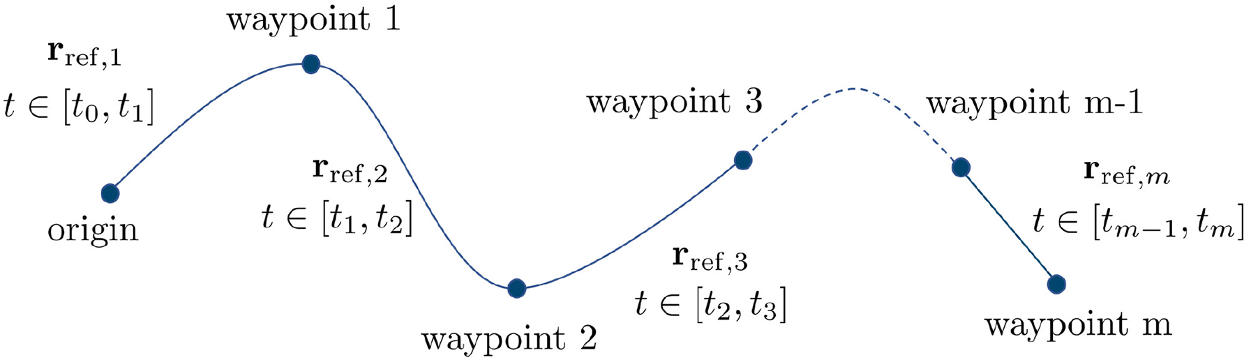
Piecewise Trajectory Generation for a Set of Waypoints.
Trajectory Generation
Based on the differential flatness property, the trajectory must be at least fourth-order differentiable. This generates a reference trajectory which is a 9th-order polynomial trajectory, with 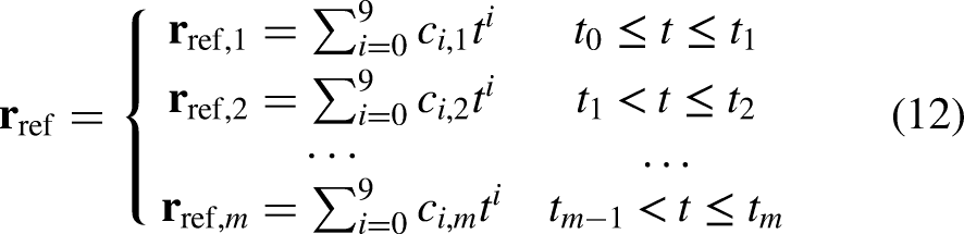


To make sure the quadrotor traverses through all the desired waypoints, position, velocity, acceleration, jerk and snap constraints are imposed using
As an example, the process to achieve a desired attitude (by controlling roll angle) is presented. The desired roll angle (

An Example Trajectory Generated for a 45 Degree Perch going from Hover (Blue) to Perched Position (Red).
Perching Trajectory
The developed inverted perching planner generates a two-stage trajectory. In the first stage, the waypoints generated take the quadrotor from its current state to the end of the half flip, ready to begin the perch. The waypoints for the second stage then take the quadrotor from the end of the half flip through to engaging the grasp on the target. The altitude of the first waypoint in the second stage is set to be slightly higher than the final waypoint of the first stage.
Performing the trajectory planning in this way has three advantages that lower the difficulty of the perching problem. Firstly, if the quadrotor is perching from underneath the simulated “branch,” it will make sure that as the quadrotor completes the half flip, it won’t crash into the “branch.” Secondly, completing the maneuver as two trajectories (with the offset altitude at the trajectory switch) causes a larger altitude error in
Experimental Platform and Manipulator
Quadrotor Overview
The custom-built, 250-size quadrotor (figure 6) was built using commercially off-the-shelf components, with the main components listed in table 2. The manipulator is custom-built from 3 mm acrylic and weighs 32 g.
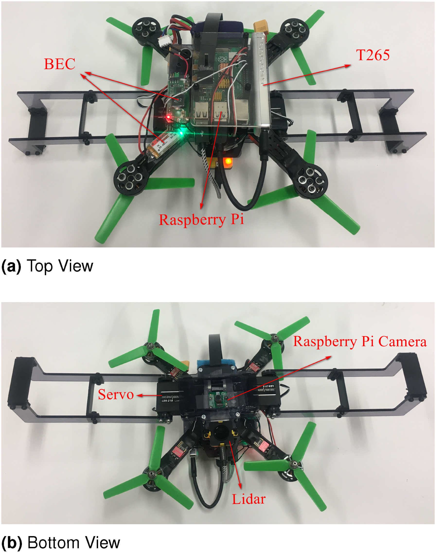
Experimental Platform Showing the Major Components Used for Compute and State Estimation.
Main Components and Weights of System.

The vision-based control implemented for this work is very simple, and is only included to demonstrate the possibility of achieving the upside-down perching maneuver without a highly-accurate external state estimate (such as from the use of Vicon or Optitrack Motion Capture systems). It also helps prove that the controller and the two-stage trajectory generation are resilient to the lower accuracy of onboard state estimates.
The simplified method presented here of determining where to perch without the pre-knowledge of the target perching location’s geometry adopts a similar idea to that of PBVS. The state estimation of the perching target is determined using an onboard VIO (Vision Inertial Odometry) sensor. The target X-Y position (in the camera frame of reference) is determined by the image information directly from the cameras, while the target Z position is determined by the depth information provided by a 1D lidar. Alternatively, depth information could also be obtained using an RGBD camera. The location of the center of the target perch is obtained by detecting the specific color of the perch, while the orientation is determined using edge detection. This concept is similar to how a UAV could potentially detect and perch on a tree branch as the colors (and shapes) of tree branches are usually fairly similar to each other. Then, the vehicle is commanded to align the center of the target perching location to the center of the camera. Here, it is assumed that the center of the camera is located at the center of the vehicle, however for a non-centered camera, offset compensation using a coordinate transform could easily be added. Once the vehicle has moved to an ideal location which is within the error threshold of the target perching location, then the manipulator is closed, achieving the perch.
Hardware System Overview
An overview of the hardware is shown in figure 7. A Raspberry Pi 4B runs the high-level controller, vision-based target tracking module, and the SBUS signal generator. On-board state estimation is provided via a T265’s internal VIO engine, and is fed into the high-level controller. A Raspberry Pi camera and an EVO-mini lidar provide image and depth information to the target tracking module. Based on the vision-guided algorithm, the desired trajectory is generated from the estimated perching location and then sent to the high-level controller. The servos are also controlled by the target tracking module based on the depth and position error. The low-level controller runs on a Kakute F7 microprocessor and communicates with the Raspberry Pi through SBUS. Importantly, the entire framework (including state estimation) is run onboard the quadrotor using on-vehicle compute proving that with relative few computational resources, inverted perching can be achieved.

System Overview of the Key Components on the Upside-Down Perching Quadrotor.
Vision Guidance
The proposed vision guidance algorithm is computationally lightweight, allowing it to be run on small, single-board computers. Using the hardware on-board the quadrotor (a Raspberry Pi 4B) the proposed algorithm runs at 5 Hz, an acceptably fast update rate for smooth and stable target tracking. Of note, the auto white balance function of the camera needs to be disabled for stable performance of the color detection module.
The vision-guided algorithm is divided into two parts for the target perching location tracking. The first part calculates the target position and orientation in the camera’s X-Y plane. The second part determines the distance in Z direction, which in turn gives the target altitude. The primary sensor in the Z direction is a lidar, however this could be replaced with another distance sensing method.
X-Y Direction Target Tracking
The X-Y Direction Target Tracking provides the target position and yaw angle for the vehicle to track to achieve the perch. The general outline of the algorithm is shown in Figure 8. The camera streams 1280
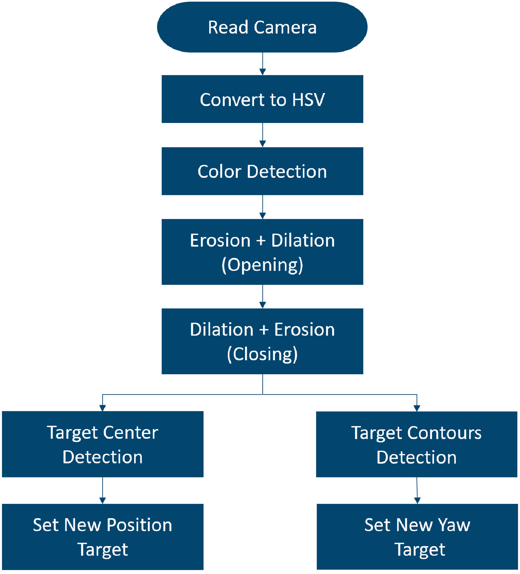
X-Y Direction Algorithm Flowchart that Converts the Raw Image into a Desired X-Y Position and Yaw Angle Target.
Position in the X-Y Plane
The center of the perching location is easily calculated from the moments generated from the binary image. The pixel coordinates of the perching location center are then fed into the X-Y direction target generator.
This generator’s goal is to move the detected center of the target perching location to a ‘goal’ coordinate on the camera image plane. As the camera is located at the center of the vehicle, taking the goal coordinate as the principle point of the camera (approximately the center of the image, (640,480) for a camera resolution of 1280
Tracking the goal pixel coordinate is handled by a simple P controller with a variable gain that scales with the distance to the target. This variable gain was introduced to account for the fact that when the vehicle is close to the target, even a small position change will induce a significant pixel difference in the X-Y direction. Thus, a constant gain would either induce an oscillation around the target perching location when close to the target, or have unacceptably poor tracking when far from the target. Here, a linear function is used to calculate the controller gain:


Yaw In the X-Y Plane
The detected contours (which define the direction of the perch) are used to determine the desired yaw angle for the vehicle. Based on the detected perching area, there are two different cases: if two contours are detected, then the camera is close to the target perching location (figure 9(A)), and, if there are more than two, then the camera is far from the target (figure 9(B)). For the case where the vehicle is close to the target, two straight lines are fitted from the points in the two contours (the red lines in the figure). The yaw angle

Visual Target Yaw Determination using Fitted Lines for the Close-Up Case (A) and the Far-from-Target Case (B).
For the case where the vehicle is far from the target (i.e. more than two contours are detected) a rotated rectangle is generated that contains all the detected contours (the green lines in the figure). The desired yaw angle is determined by the rotation angle of the generated rectangle. The contours of the perching area are found by the Canny method provided in the OpenCV library.

Hough Transformation used to Project from the Camera Plane into the Aircraft Body Frame.
This algorithm operates with the underlying the assumption that the desired target perching location resembles a rectangle, and the desired perching orientation is along the Y axis. For this work, this is a reasonable assumption given that the projection of a tree branch on a camera image plane typically resembles a rectangle. Due to the modular nature of the framework presented here, a more complex ‘tree branch / perching target’ detection algorithm could be implemented easily in the future, without the need to modifying any of the other existing software.
If two lines are detected, then a Hough transformation is needed to determine the yaw angle. With the Hough transform, lines are represented in the form of


Z Direction
Tracking the target perching location in the Z direction must be treated differently to the position control in the X-Y plane. After the half-flip, the lidar sensor now faces upward and towards the perch. Thus, anything detected by the lidar could be the potential target perching location. The lidar used in this work (a Teraranger EVO Mini) has a field of view of 27 degrees (compared to the camera’s 48 degree field of view), meaning that it is possible that the target perching location is not within the field of view of the lidar after the half-flip. In this situation, the vehicle keeps the current altitude and only moves in the X-Y direction until the lidar detects a suitable target.
Figure 11 presents a flow chart of how the tracking algorithm in the Z direction is implemented. First, the depth information 

Z Direction Algorithm.
Experiments
Each element of the proposed upside-down perching framework was verified independently through flight testing before being combined together to run the full framework on-board the vehicle. Reliable target detection is the foundation of a successful target tracking. Meanwhile, the capability of conducting a half-flip with the T265 is also critical to the final test. By combining the capability of target tracking and conducting the half-flip maneuver, the final test of perching upside down with vision guidance could be verified.
Target Detection
The first element that was tested was the target detection.
Figure 12(A) shows a raw image captured by the Raspberry Pi camera on approach to the perch, and the extracted perching area binary image (figure 12(B)).
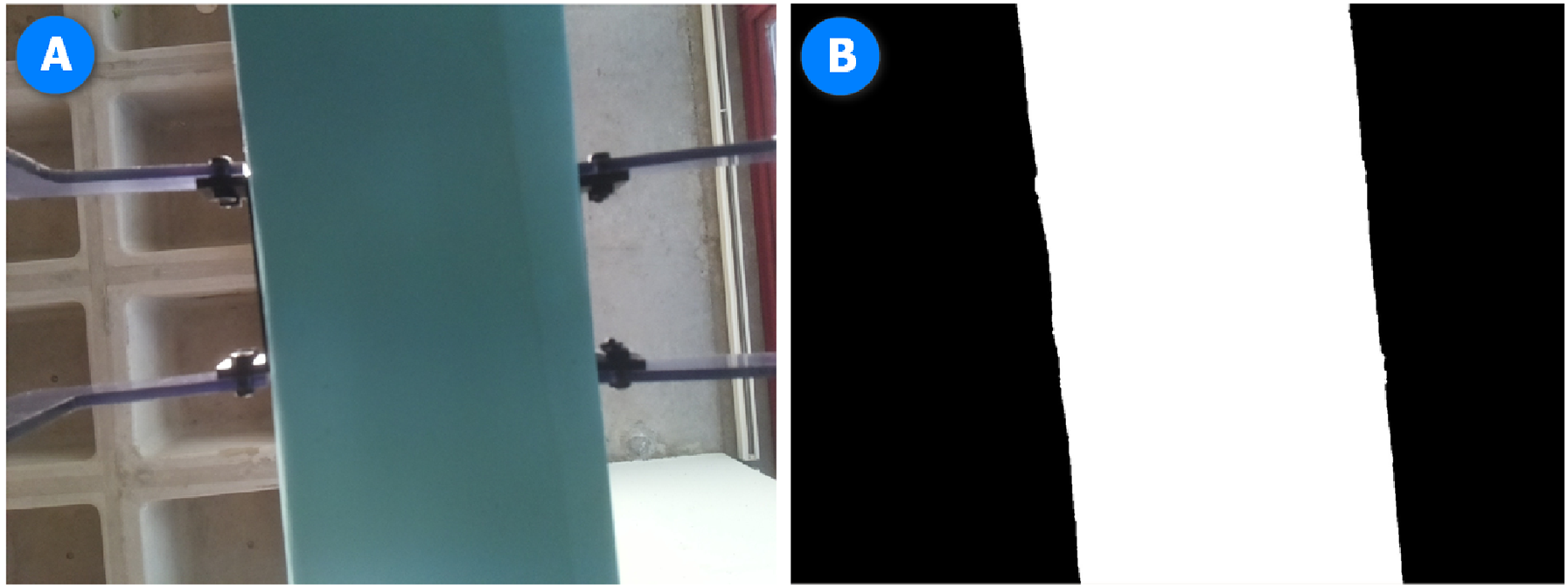
Target Detection.
Several tests were required from different angles to generate the set of tuning parameters that gave a high true positive detection rate whilst minimizing the false positive rate. This test verifies the perching location detection for the vision-guidance algorithm.
Target Tracking Test
Next, the X-Y plane target tracking was tested with the quadrotor. The simulated “branch” with the target perching location (labeled with a specific color) was moved around manually in the X-Y plane and the quadrotor was commanded to track the target dynamically (figure 13, video at https://youtu.be/-ZJiugEcuxw.). This test verifies the effectiveness of the vision-guided algorithm to track a target in the X-Y plane.

Target Tracking in the X-Y Plane. The quadrotor was commanded to remain a fixed distance below the target perching point (marked with blue tape).
Perching Upside-Down Using Vision Guidance
Each element was then tested together, and the full upside-down perching framework put into effect. Initially, the quadrotor was set to hover a short distance away from the target perch. The half-flip maneuver was then commanded after a preset time, flipping the vehicle upside down and allowing the camera to start tracking the target. The vision-based guidance then positioned the quadrotor to within grasping distance of the perch. Once the desired position and velocity errors were within a preset threshold, the manipulators were engaged and motors stopped. Figure 15 shows several still of the process in action, with the full video available at https://youtu.be/lnQGzARQKU0. A summary of the complete hover-to-perching process is shown in figure 14.

Automatic Perching Process.

Frame Captures Showing the Vision Guided Upside Down Perching.
A graph of the vehicle states during the upside-down perching maneuver is shown in Figure 16. The graph shows the platform initially starting from hover, conducting the half-flip (t=2s), and then hovering in an inverted state (t=3s to t=13s). The vision based guidance is then engaged to move the platform to the target perching location.

Flight Log Showing the States during the Upside-Down Perching Maneuver.
During testing, the quadrotor successfully transitioned from upright hover to an inverted perching maneuver 80 % of the time (10 tests were conducted). The primary causes of failure are discussed in the Discussion section.
Conclusion, Discussion and Future Work
Contribution
In this work, a generalized vision-guided, inverted perching implementation framework has been proposed and experimentally verified. Due to its modularity, the algorithms presented here can easily be customised towards specific research requirements. The control module and motion planning module are designed so that a quadrotor can operate in both upright and inverted flight modes. These two modules work together to ensure a minimal loss in altitude during the inverted perching maneuver. The proposed vision-based guidance, while simple and computationally light, is sufficient for a demonstration of the proposed visual guided implementation framework.
Discussion
As noted previously, one current challenge for the proposed framework lies in the guidance module, where the currently-implemented visual guidance method has common perception problems related to computer vision, such as sensor noise, changing illumination and motion blur. These problems play an essential role in test failures. Based on multiple tests with the vision guidance algorithm and the performance of the T265, test environment illumination condition is the most critical factor in the current setup (due to lighting having a direct effect on shutter speed and hence motion blur). As a test, the pose estimate from the T265 was compared with pose estimate from a motion capture system (Optitrack). Though the position estimate provided by the T265 is not as accurate as one provided from a motion capture system (such as Optitrack or Vicon), the proposed method still works as it computes the relative pose error between the current platform and the target, rather than the absolute position in space of both.
Future Work
A more aggressive way of achieving inverted perching may be to omit the second stage in the two-stage perching trajectory used in the motion planning module, and instead produce a dynamic trajectory that combines the flip maneuver with the perching target approach. This will present significant challenges to the quadrotor controller, trajectory generator (including servo control command), however would produce an elegant, bio-mimetic solution, and would be a valuable direction for future investigation.