
Abstract
In this article, we describe a visual/inertial integrated carrier landing guidance algorithm for aircraft carrier landing operations. The airborne vision system and the inertial navigation system are employed as sensors to obtain feature points of carrier runway as well as the aircraft inertial measurements. In this algorithm, visual and inertial information are integrated, and the Pose from Orthographic Projection and Scaling with Iterations algorithm is utilized to estimate aircraft position and carrier motion. A simulation was constructed validating this algorithm, and the results of this simulation show satisfactory accuracy as well as high efficiency in carrier landing guidance.
Introduction
The carrier-borne aircraft is one of the most important constituents of the aircraft carrier. However, the complex landing environment can potentially lead to a landing failure because of a small landing area, carrier motion, and occasional conditions of low visibility. 1 Aircraft carrier landing is one of the most difficult operational challenges in the world.
For a safe landing operation, various kinds of landing guidance systems are developed for guiding aircraft to follow accurate slope–slide path and reach touchdown position, such as a shipboard tracking radar system 2,3 and Shipboard Relative Global Positioning System. 4,5 These guidance systems can meet the typical carrier landing requirements but lack guidance capacity when wireless communication cannot function.
With the development of photoelectric technology, the airborne vision-guided technology, which can be considered as an autonomous navigation technology, has attracted attention in aircraft landing research. Sharp et al. 6 and Saripalli et al. 7 used specially designed planar features to land a helicopter. In the work of Gui et al., 8 maximum between-class variance algorithm, region growing algorithm, and negative Laplacian of Gaussian operator are used to detect and track centers of the infrared lamps in the images. In a previous study, 9 the runway boundary lines were extracted using Hough transforms, and the lateral offset of the unmanned aerial vehicle (UAV) was estimated with respect to the runway centerline. All these methods can be applied to landing on an aircraft carrier. In the work of Yakimenko et al., 10 three infrared points were used to calculate the relative position and orientation of a UAV with respect to a ship. A three-dimensional (3-D) model-based tracker was used to estimate the camera poses, and their detection targets are a warped patch of a reference image, three visual features including two white triangles on the runway and a white line along the stern. 11,12 However, the methods mentioned above cannot estimate the ship motion, and their results can potentially be improved for greater accuracy. Ding et al. 13 estimated the ship motion using Newton’s iterative algorithm, but there is still room for improvement in terms of accuracy and efficiency.
This article presents a visual/inertial integrated carrier landing guidance algorithm that requires less execution time as well as eliminates the need for Jacobian determinant calculation in Newton’s iterative algorithm. In this algorithm, the Pose from Orthographic Projection and Scaling with Iterations (POSIT) algorithm is utilized to estimate the relative position and attitude between the aircraft and the carrier from visual information, and the carrier motion can be decoupled by using the aircraft attitude information from the airborne inertial navigation system (INS). Then, the changing position of the landing point caused by carrier motion can be estimated, and the optimal trajectory can be planned according to the height of the landing point. The position of the aircraft deviating from the optimal trajectory is calculated and delivered to the aircraft control system. A simulation is constructed to validate the performance of the algorithm.
This article is organized as follows. An overview of the visual/inertial integrated landing guidance system, the mathematical model, and the details of the landing guidance algorithm are presented in the “Materials and methods” section, followed by simulation and comparison of the results in the “Simulation” section, and finally, concluding remarks in the “Conclusion” section.
Materials and methods
System overview
We consider an infrared system as the airborne vision system. The infrared system is installed in front of the aircraft, and four infrared cooperated targets are set on the deck for carrier identification and location. Other common vision systems can also apply the method discussed in this article for the pose estimation after completing the recognition of characteristic points.
The schematic of system is shown in Figure 1. The four red points represent the four cooperated targets that are set on the deck for visual detection.

The vision system and the cooperated targets.
The vision system gauges the image of the runway containing cooperated targets and utilizes image recognition methods such as the maximum between-class variance algorithm, 8 edge extraction based on Canny operator, and contour-based moment algorithm to recognize the image coordinates of the targets’ centers. There are one-to-one relationships between the two-dimensional (2-D) infrared image coordinates on the vision system and the real 3-D position of infrared cooperated targets on the carrier. Through this relationship, the POSIT algorithm calculates the relative pose between the aircraft and the carrier. By integrating the aircraft attitude measurements from the INS, the carrier motion can be decoupled from the relative pose information and then utilized to calculate a reference flight path. All landing guidance information is delivered to the flight control system (FCS) for controlling the aircraft.
The complete block diagram for the carrier landing guidance system is shown in Figure 2.

The visual/inertial integrated carrier landing guidance system block diagram.
Coordinate system
The aircraft carrier is assumed to be at sailing straight with typical roll, pitch, and heave dynamics, which have considerable influence on the position of landing point. The aircraft is gliding to the expected landing point with a horizontal angle of 3.5°.
The frames involved are shown in Figure 3. All coordinate systems are right-handed. The frame FO is defined as the navigation coordinate, where the y-axis coincides with the runway centerline and the z-axis points upward. The aircraft body frame FB and the carrier body frame FS are designed with the z-axis oriented upward and the y-axis pointing to the head. The carrier runway frame FR corresponds to the expected landing point on the carrier deck, translated by the offset vector

Coordinate system.
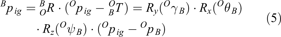
The pose of the aircraft and the aircraft carrier in FO are, respectively, defined as

and

where
The coordinates of the four infrared cooperated targets are expressed as


where


According to the imaging principle in the study by Trawny et al.,
14
the conversion relation between the coordinates
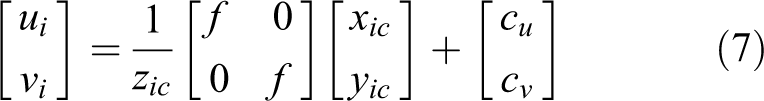
where f is the focal length of the camera and
Algorithm
The POSIT algorithm can estimate the object pose in a camera frame from a single image if four or more correspondences between 2-D points and 3-D points are given. The algorithm consists of two steps. First, the scaled orthographic projection is used to approximate the perspective projection and get the rotation matrix and translation vector from a set of linear equations. Second, the new scale factor is iteratively calculated for each point, and the first step is repeated using the new points instead of the original ones until the set threshold is met. 15 –17
Figure 4 shows the perspective projection and scaled orthogonal projection. The target frame FD is parallel with the runway frame FR and its origin point is the first cooperated target p0g. The points denoted by Pig are the perspective projection points on the camera focal plane. P′ ig points are called scaled orthogonal projections.

Perspective projection and scaled orthogonal projection.
The coordinates of the points denoted by pig in FD and FR have the following relation
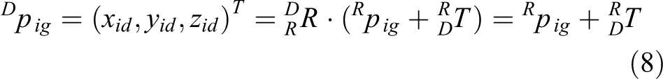
where
The image coordinates can be expressed as

where
By introducing a range scaling factor s = f/Tz, equation (9) can be rewritten as

Considering

The following linear equations result

Coinciding with scaled orthogonal projection, the initial values of perspective projection
However, if

Two solutions of I3 and J3 can be obtained by solving this equation. According to the characteristics of the rotation matrix

where
In equation (14),
Because both R1
T
and R2
T
are unit vectors, s,


As the pose estimation in the first step has been obtained, better estimations of wi can be obtained using equation (10). Then, by substituting the new wi estimations into the linear equation (12), we can get more accurate results. This iterative process will end when
In accordance with the formulas (3) to (6), the following can be derived
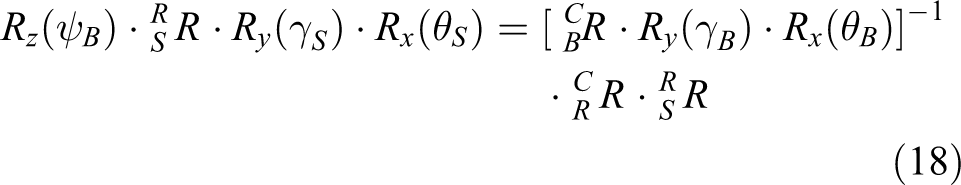
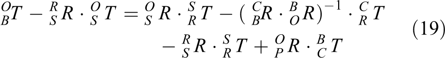
The right-hand side of equation (18) is formed by known values, so ψB, γS, θS, and the entire rotation matrix can be calculated. Assume that
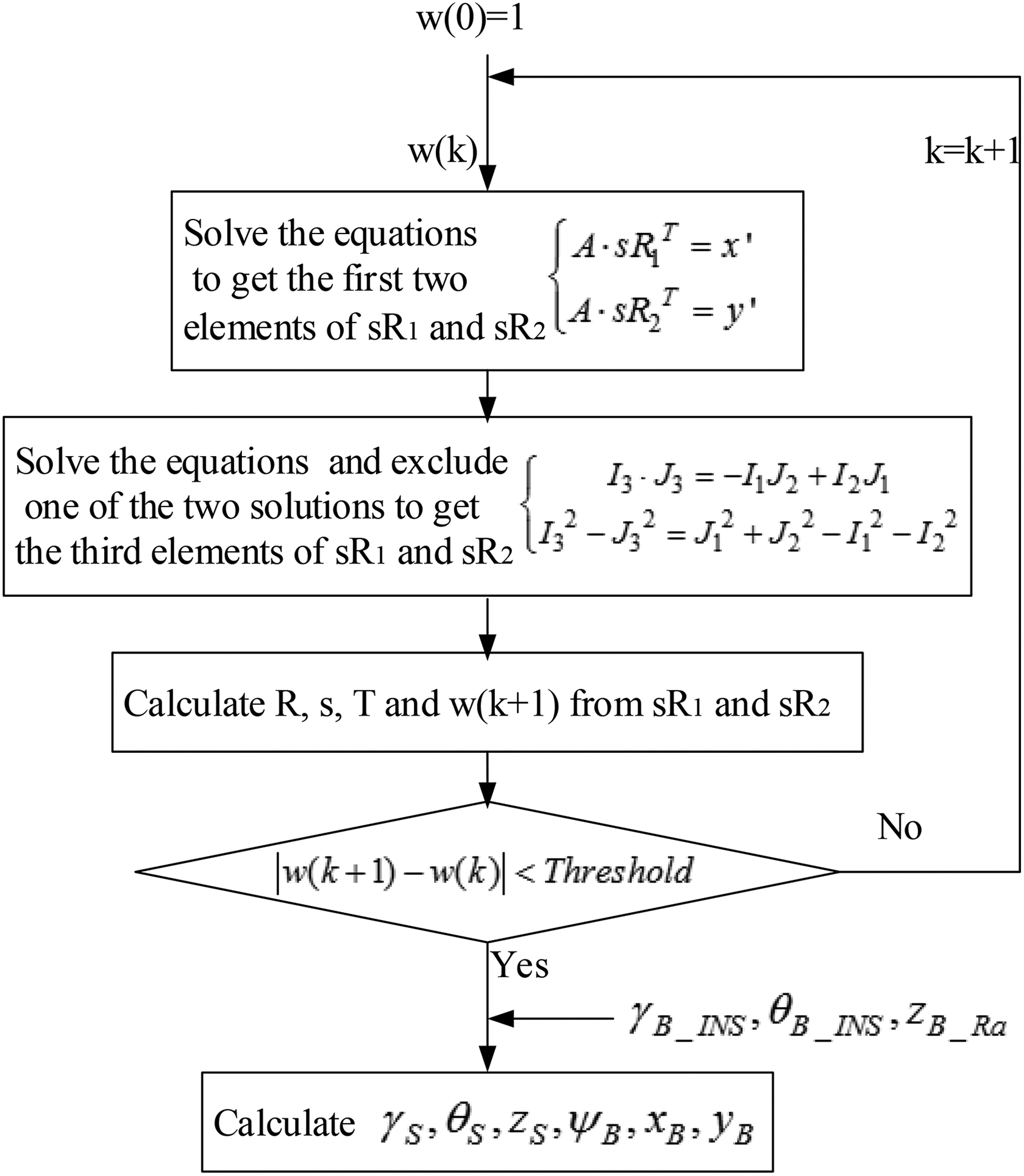
The schematic of the algorithm application.
Control law
The optimal linear quadratic regulator (LQR) is employed in this study. LQR is a common method to analyze multiple-input multiple-output FCS in modern control theory. 18
The reference trajectory can be calculated according to the aircraft carrier motion (γS, θS, and zS). Then, the off-glide-path lateral distance dx, vertical distance dz (both refer to modified reference trajectory), and velocity V are obtained as inputs to the control law. The control objective is to regulate these variables to a value of zero for keeping the aircraft on the glide path. Therefore, the vertical state vector xv and the lateral state vector xl can be expressed as follows

where α, β, θ, ϕ, q, p, and r are the attack angle, sideslip angle, pitch angle, bank angle, pitch rate, roll rate, and yaw rate, respectively. States of the aircraft are observable by using aircraft sensors.
The control vector is defined as

where δt, δe, δa, and δr are throttle, elevator, aileron, and rudder deflections, respectively. In the control vector, the throttle and elevator deflections are used for aircraft vertical control, and rudder and aileron deflections are used for aircraft longitudinal control. State feedback is utilized and the control inputs are computed as follows
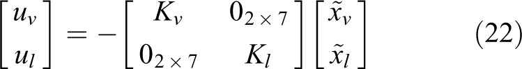
where Kv and Kl are state feedback gains. The optimal LQR method is used to compute the state feedback gains with the weighting matrix defined by Brian and Frank 18

Simulation
A simulation is discussed for validating the performance of the visual/inertial integrated landing guidance algorithm. In this experiment, the aircraft carrier is assumed to move at a speed of 20 knots (about 10.3 m s−1), with governed by classic carrier dynamics. 19 –22 The simulation starts when the aircraft is 1500 m away from the aircraft carrier. The aircraft model in this control law simulation is assumed to be F-14. The carrier model is assumed to be the American Nimitz-class aircraft carrier, and the coordinates of the cooperated targets in the carrier runway frame are (15, −65, 0), (−15, −65, 0), (15, 175, 0), and (−15, 175, 0), respectively. Sea-state level 3 in the study by Sweger 19 is chosen as the experimental condition. The root mean square (RMS) amplitudes of the heave, roll, and pitch are 0.91 m, 0.32°, and 1.08°, respectively. The air wake is considered using the model in the American Air Force manned aircraft flight quality specifications MIL-F-8785C.
The resolution and field of view of the vision system are 768 × 576 and 8° × 6°, respectively, whereas the output frequency is 25 Hz. The focal length calibration errors of the vision system are less than 0.2%. The target coordinate extracting errors are less than two pixels, and they decrease as the distance between the aircraft and the carrier decreases. The INS is assumed to have initial errors in attitude, velocity, and position measurements, and the drift error of the gyroscopes is 0.01° h−1, whereas the accuracy of the accelerometers is 50 µg.
Guidance performance
The guidance simulation involves estimating the carrier motion as well as the relative position between the aircraft and the carrier. Figure 6(a) and (b) shows the aircraft carrier motion estimation errors and standard deviations. Figure 7(a) and (b) shows the aircraft motion estimation errors and standard deviations. The horizontal axes in these figures are the real longitudinal distances between the aircraft and the carrier.

(a) The aircraft carrier motion estimation errors in one landing phase, including the roll, pitch, and heave and (b) the standard deviations of the aircraft carrier motion estimation errors calculated from 20-time carrier landing.
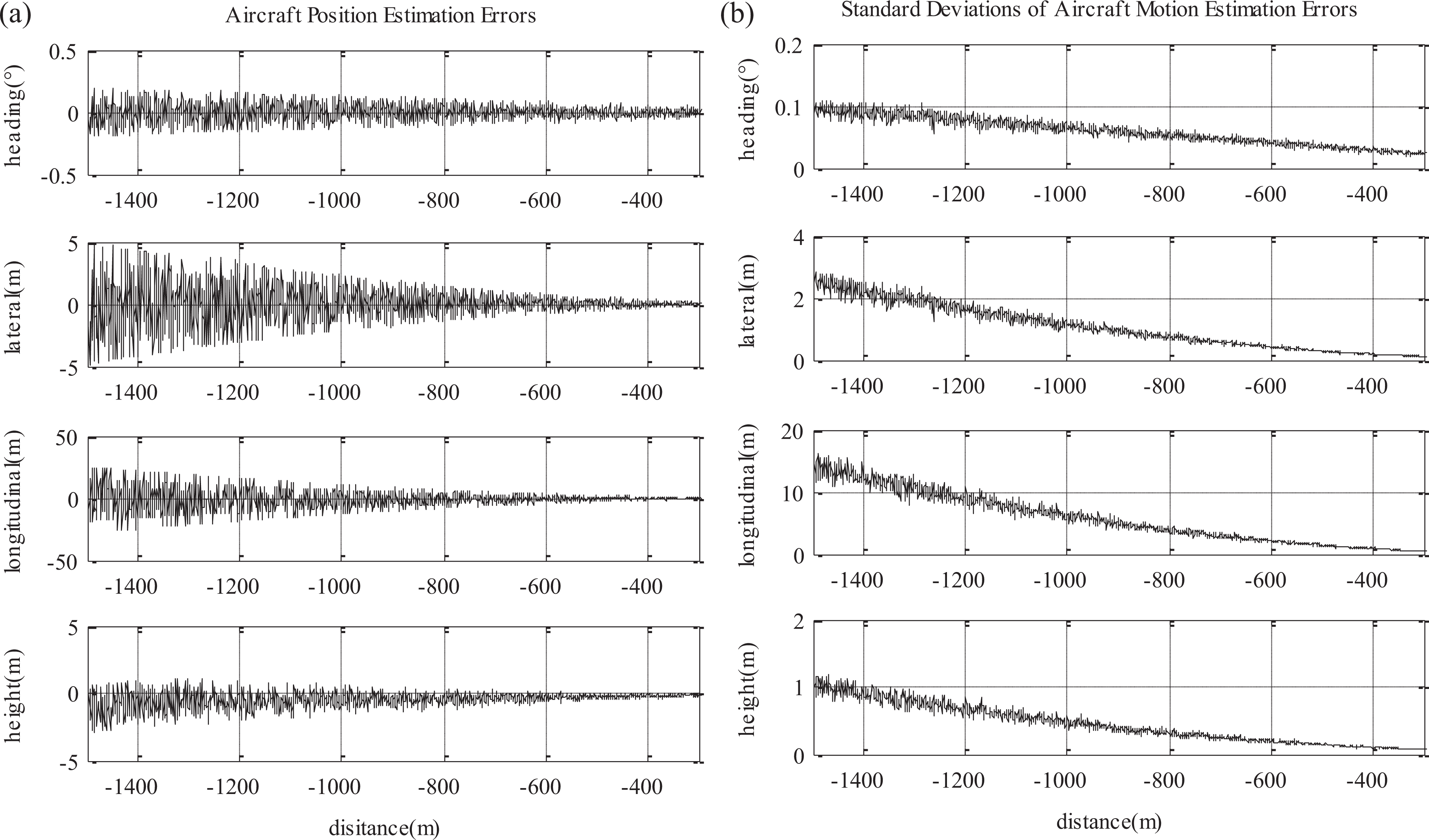
(a) The aircraft motion estimation error, including the relative heading angle, the relative lateral position, longitudinal position, and height and (b) the standard deviations of the aircraft motion estimation errors calculated from 20-time carrier landing.
As shown in Figures 6 and 7, the initial estimation errors exist because of the initial attitude error from the INS, the focal length error, and so on. As the aircraft approaches the carrier, the estimation errors reduce in value. When the distance between the aircraft and the carrier is less than 400 m, the aircraft position estimation errors converge to 0.5 m in lateral distance, 0.8 m in vertical distance, 2.5 m in longitudinal distance, and 0.1° in the heading angle estimation. The carrier motion angle estimation error is less than 0.2°, whereas the heave estimation error is less than 0.8 m.
Several algorithms that can be utilized in vision-based carrier landing guidance system have been researched. For comparison, Newton’s iterative algorithm, an algorithm from École Polytechnique Fédérale de Lausanne (EPFL algorithm), and the planar homography algorithm have also been studied. The details of the other three algorithms can be found in the works of Ding et al., 13 Hajri, 17 and Moreno-Noguer et al. 22 and Yang et al., 23 respectively.
Table 1 lists the data obtained by simulating the carrier landing 20 times and presents the max and standard deviation of estimation errors, and the max and average values of execution time when the longitudinal distance between the aircraft and the carrier is 400 m. As presented in Table 1, the estimation error of the algorithms based on EPFL and planar homography is too large to meet the landing requirements, so the standard deviations of the estimation errors of those two algorithms are not given.
Comparison of the estimation results using the four algorithms.

POSIT: Pose from Orthographic Projection and Scaling with Iterations; EPFL: École Polytechnique Fédérale de Lausanne; Max: maximum; Avr: average; Std: standard deviation.
The algorithm proposed in this article has advantages in terms of the execution time and comparative accuracy when compared with Newton’s iterative algorithm. Considering the difficulty of the engineering application, execution time, and estimation accuracy, the algorithm in this article is slightly better than Newton’s iterative algorithm.
Control law
The simulation for the control law validation is discussed subsequently. Figure 8(a) shows the aircraft lateral position

(a) The aircraft lateral position in the carrier body frame and the off-glide-path lateral distance and (b) the aircraft height in the carrier body frame and the off-glide-path vertical distance.
Conclusion
In this article, a new visual/inertial integrated carrier landing guidance algorithm based on POSIT was designed to calculate the aircraft pose and carrier motion in the carrier landing operation. The simulation performed using this algorithm was discussed for validation, and the results show that this algorithm performs precisely with respect to calculating landing estimates and satisfactory control response. On comparing simulation results across algorithms, it is obvious that this algorithm has unique advantages in terms of the execution time, comparative accuracy compared with Newton’s iterative algorithm, and much better performance than that of the algorithms based on EPFL and planar homography. These results can be applied in carrier landing operations.
Footnotes
Declaration of conflicting interests
The author(s) declared no potential conflicts of interest with respect to the research, authorship, and/or publication of this article.
Funding
The author(s) received no financial support for the research, authorship, and/or publication of this article.