
Abstract
For some years, bi-directional porous aero-thrust bearing systems have been receiving much attention. They are now applied extensively where there is a need for rigidity in high-precision instruments and mechanisms that run at high speed. Although the carrying capacity of gas bearings is not as good as that of oil film bearings, the heat generated at high speed is lower and does not cause spindle deformation. Under certain conditions, the shaft will display unstable non-periodic movement, and this can even become chaotic. This irregular behavior, when serious, can even damage the mechanical parts, cause a breakdown, and stop production. The aim of this study was to gain an understanding of this phenomenon and the conditions under which it might arise and to find a means for avoiding irregular vibrations and eliminating the air hammer effect that accompanies them. A detailed examination of the related characteristics of a gas bearing shaft system was carried out using numerical value analysis such as the finite difference and differential transformation methods. An analysis of the nonlinear dynamic behavior of the main axis was then carried out using bifurcation diagrams, Poincaré sections, and spectral response.
Keywords
Introduction
A bi-directional porous aero-thrust bearing (BPAB) is very different from ordinary bushed, ball, or roller bearing systems. 1 The shafts supported by ordinary bearings generally run at speeds that may be as high as 14,000–24,000 r/min, and the DmN value upper limit is about 2 × 10⁶. The spindle acceleration indicator (DmN) is related to bearing material, structural design, bearing capacity, accuracy, critical speed, and others. However, aerostatic spindle speeds can be higher than 30,000 r/min, and the DmN value is much greater than 2 × 10⁶. The main advantage of these bearings is the absence of contact between the bearing surface and shaft. The working life of such a system is very long because there is so little wear. Furthermore, because gas is compressible, and has low viscosity, fluid shear is also very small. This means not very much power is needed to achieve very high speeds and so little heat is generated that dynamic performance is unaffected even in a high temperature working environment. Since the lubricating agent used in such a system is air, environmental contamination is not a problem and operation is possible at extremely high rotation speeds at high or low temperatures. The gas homogenization effect also can effectively compensate for some processing imperfection in the original bearing and shaft surfaces. This can be of great value for rotational and translational accuracy in machines. Such gas bearings can be used as machine tool components for circularity and linear reference, ultra-precision machining technology, and micro-processing technology. The precision and stability of these bearings give them research level production and manufacturing standards suitable for the most demanding ultra-precision machining technology. 2
Gross 3 published a chart from 1950 to 1970 that could be used to calculate air bearing performance. Rieger and Wilcock 4 devised simplified methods for bearing design, taking load, flow, and stiffness into consideration. Powell 5 published a design chart for the load capacity of a light load bearing. The precise calculation and distribution of air film pressure has been an important topic of gas bearing research and analysis. All the references shown above included methods for solving the formulae and also contain simplified analytical and numerical solutions. In 1991, Nguyen, 6 Malik and Bert, 7 and Wang and Schellekens 8 proposed the use of the finite element method (FEM) for solving air bearing pressure distribution questions in the complicated boundary. In 1994, Han et al. 9 used the finite volume method to solve the air bearing stiffness and damping coefficients and also to calculate the trajectory of the bearing. In 1974, Bently 10 studied the dynamic behavior of rotors and found through experiment that rotor bearing systems displayed second- and third-order sub-harmonic vibration. Then in 1984, Muszynska 11 and Ehrich 12 also found sub-harmonic vibrations in an experimental rotor bearing system. Childs, 13 Choi and Noah 14 used analytical methods to prove the presence of sub-harmonics in a rotor bearing system. However, this work was done with oil film bearings and studies of gas bearing systems were quite rare. In 2006, Wang 15 used the finite difference method (FDM) to solve the air film pressure in a static pressure type porous gas bearing system and published trajectory and spectrum charts and bifurcation diagrams in an analysis of the dynamic behavior of the rotor and journal center. The study showed that the rotor center developed periodic, quasi-periodic, or sub-harmonic motion under different operating conditions. Subsequent analyses of other gas bearing systems showed that within a specific operating range, the system will even develop nonlinear chaotic motion.16–19 In some real situations, 20 bearing cannot work normally, especially for high pressure and heavy load gas bearings.21,22 Moreover, the pneumatic or whirl instability is likely to occur if aerostatic journal bearing is working at very low or high speed. 23 Therefore, how to improve the stability and avoid the occurrence of non-periodic motions is very important to the promotion and application of gas bearings.
However, none of the above references dealt with BPAB systems, and the integration and verification of theory with experiment work were rare. Nowadays, production speed and efficiency are absolute requirements, and the study and implementation of rotary motion with both high precision and high stability has become an important research direction and is also essential for modern industry as well as academic research. It is also the main point of this study.
Research method
This study was focused mainly on porous air film thrust bearing systems that have become a requirement of the precision machinery industry. They are especially applicable to the field of ultra-high-speed devices where a high load-carrying capacity is also needed. Currently, most porous air film thrust bearings are unidirectional surface type, as shown in Figure 1. The biggest problem with such bearing is a short life caused by momentary contact between the bearing surfaces and the resulting wear or damage. When the spindle is started or stopped and sometimes even during normal operation, the surfaces may collide. These collisions between the surfaces lead to damage, and pores may become blocked. If gas flow is impeded by blocked pores, the surface support force can be reduced making the bearing ineffective. This kind of system is prone to instability and bearing, and rotor collisions are quite frequent.

Unidirectional porous thrust bearing.
This study presents an analysis of round flat plate type BPAB systems, as shown in Figure 2. In these bearings, the rotor (or load) is supported in the middle by the same bearing in both the up and downward directions as well as sideways. Bearing strength is developed from the upper and lower, sideways, differential pressure produced by the eccentricity of the object. This is known as the double film effect, and the parameters corresponding to the upper and lower film are denoted by the subscript i = 1 and 2. The pressure distribution function of upper and lower film can be derived according to the lubrication equation for a single film thrust bearing, as shown in formula (1)

When the eccentricity is ε, the upper and lower gaps are

A bi-directional porous aero-thrust bearing.
The boundary condition is as follows:
When
When
When
When
The pressure function can be obtained from the numerical calculation, and after integration, the load, stiffness, and flow results can be obtained as follows


The motion behavior of the rotor is analyzed, as well as the dynamic trajectory, spectral response, and the bifurcation behavior. Poincaré mapping analysis is also done at this time.
The hybrid method was used to analyze the bearing system, and the numerical results were compared with those obtained by traditional FDM and perturbation method. Accuracy testing and verification of the key performance coefficient were carried out.
Gas film pressure distribution can be obtained by calculation as a follow-up of the rotor dynamic characteristics. The rotor was considered to have mass mr, and the bearing was fixed to a rigid base. Under these assumptions, the movement of the rotor can be regarded as being in the X-, Y-directions.
In the transient state, the balance equation of the rotor center is as follows

Among these,
Iterative calculations were used to determine the dynamic behavior of the rotor and the associated bearing parameters. Acceleration, velocity, and displacement were calculated over time. The initial condition of the system was taken as static. The initial displacement of the rotor (
The calculation steps are as follows:
Step 1. At time
Step2.The displacement of the rotor center obtained from Step 1 is substituted into the rotor force balance equation to obtain the new rotor center position. The thickness of the gas film
Step 3. The pressure distribution obtained from Step 2, is used in the integral equations (6) and (7) to produce new gas film supporting strength, stiffness, and damping coefficients


Step 4. A new set of initial conditions is formed using the displacement and velocity values obtained in Step 1, the pressure distribution obtained in Step 2, and the gas film force obtained in Step 3. When the time increases by
The four steps described allow the pressure distribution at each time point, the relationship between gas film thickness and position changes, gas film support force changes, rigidity coefficient, damping coefficient and rotor dynamic trajectory, and other related values to be obtained. With the Poincaré map as the main criterion for judgment, periodic, quasi-periodic, and aperiodic phenomena predictions can also be made with respect to important influential factors such as different bearing number (rotational speed) and rotor mass. At the same time, the stable and unstable areas of the bearing system can be established.
Results and discussion
Numerical analysis results
Three different numerical methods were used in the analysis of this bearing system. The results show that the hybrid method24,25 combining the differential transformation method (DTM) and FDM and conventional finite difference and perturbation methods have a better fit in larger rotor mass. It also shows that the hybrid method proposed in this article has higher accuracy for BPAB system. Comparisons of the numerical values of the trajectory of the rotor center are shown in Table 1.
Comparisons of calculated values of rotor center displacement.

FDM: finite difference method; DTM: differential transformation method.
In the numerical stability analysis, the effects of different time intervals on the numerical values were also investigated, and the displacement changes under different operating conditions were compared with the Poincaré map value, as shown in Tables 2 and 3:
Comparison of different time intervals, with Poincaré map values for the rotor center for rotors of different masses computed by the DTM and FDM hybrid method.

FDM: finite difference method; DTM: differential transformation method.
Comparison of different time intervals, with Poincaré map values for the rotor center for rotors with different bearing numbers computed by the DTM and FDM hybrid method.

FDM: finite difference method; DTM: differential transformation method.
From the above numerical results, it can be seen that the hybrid method studied in this article has good convergence and is applicable to a gas bearing system. The trajectory of the system can be effectively calculated for either the rotor mass change or an increase in bearing number. To shorten the subsequent computation time for the bifurcation characteristics of a system, using the test results shown in Tables 2 and 3, the selected time interval need not be too fine. Sufficiently accurate dynamic analysis results can be obtained using a time interval of π/300.
Rotor dynamic behavior analysis of a gas bearing system
The effect of the rotor mass on the BPAB system
Bearing number (speed) of the bearing system is Λ = 4.2, and the mass of the rotor mr is regarded as a bifurcation parameter.
Dynamic trajectory and phase plane
It can be seen from Figure 3(a) and (b) that the trajectory patterns of the rotor center with a rotor of low mass (mr = 0.021) are irregular. When the mass rises to mr = 0.033, irregular movement is replaced by cyclical behavior. When the rotor mass reaches mr = 0.19, the dynamic trajectory continues periodic motion, but at mr = 0.257, this periodic response changes to non-periodic motion. When mr = 0.298, the system converges to periodic motion and finally when mr = 0.304, the bearing system maintains stable cyclical behavior.

Dynamic trajectory of the rotor center when the mass of the rotor is: (a) mr = 0.021, 0.033, 0.19, 0.257, 0.298, 0.304, (b) phase plane, (c) spectral response graph of the rotor center in the horizontal direction, and (d) vertical direction. System bearing number Λ = 4.2.
Spectrum analysis
Figure 3(c) and (d) display the dynamic response of the rotor center in both the horizontal and vertical directions. It has been shown that when the mass of the rotor mr = 0.021, the rotor center presents quasi-periodic motion. When mr = 0.033 and 0.304, the spectral response (see Figure 3(c) and (d)) shows that movement at the center of the rotor is T-periodic in both the horizontal and vertical directions. As the rotor mass changes to mr = 0.19 and 0.298, the movement becomes sub-harmonic (2T-periodic). With increased mass mr = 0.257, the dynamic trajectory mutates to quasi-periodic motion.
Bifurcation diagram
As shown in Figure 4, the rotor mass mr is taken as an analysis parameter and used to explore the effects of different rotor mass on the system. For actual operation, the mass is set between 0.01 and 0.32. It can be seen in Figure 4 that when mr < 0.033, the rotor center shows quasi-periodic motion in both the horizontal and vertical directions, and this is also shown in the Poincaré sectional view in Figure 5(a). However, this quasi-periodic motion is replaced by periodic motion when the mass is increased to mr = 0.033, see Figure 5(b). This state is maintained within the range of 0.033 ≦ mr < 0.098, but with increased mass mr = 0.19, the quasi-periodic motion is quickly transformed into 2T-periodic motion, also illustrated in Figure 5(c).
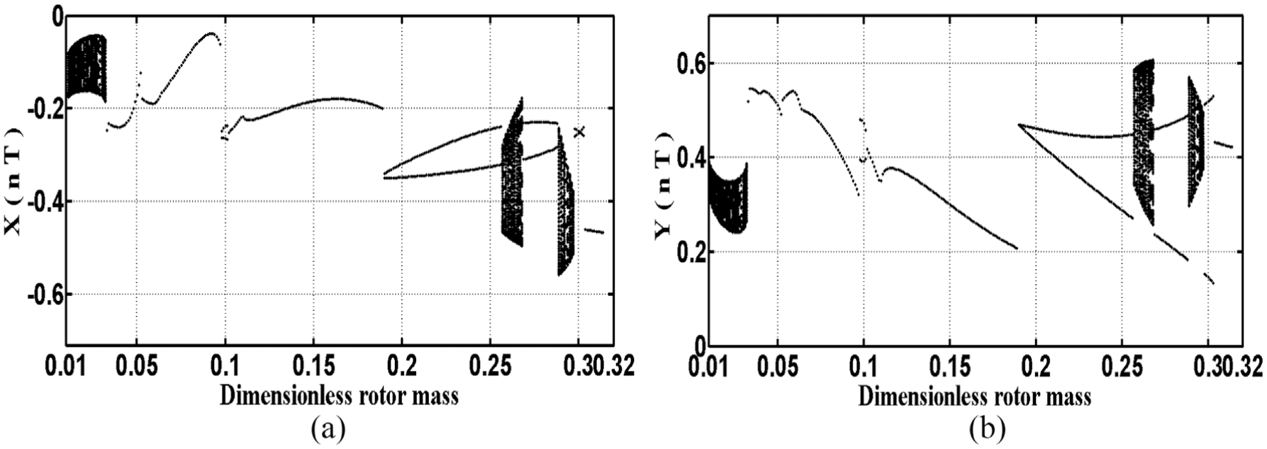
Bifurcation diagram of the rotor center for different masses of rotor: (a) X(nT) and (b) Y(nT) with system bearing number Λ = 4.2.

Poincaré sectional view of the rotor center with different rotor mass: (a) mr = 0.021, (b) mr = 0.033, (c) mr = 0.19, (d) mr = 0.257, (e) mr = 0.298, and (f) mr = 0.304.
When the mass increases to mr = 0.257, the system motion becomes quasi-periodic, see Figure 5(d), which is only maintained over a range of 0.257 ≦ mr < 0.269. As the mass continues to increase to mr = 0.269, the quasi-periodic motion originally held by the system bifurcates into 2T-periodic motion. When mr = 0.289, motion of the system changes and becomes quasi-periodic. Again, this motion state is maintained only over a range of 0.289 ≦ mr < 0.298, after which the motion of the system is in the form of 2T and T vibrations and when mr = 0.298 and 0.304, the system is also in a 2T- and T-state of motion, further shown in Figure 5(e) and (f). These findings show cyclical movement patterns with a considerable degree of sequential behavior. Table 4 shows an overall summary of the movement patterns presented by the system when rotor mass changes.
The dynamic behavior of the rotor center with changes in rotor mass.

Figure 5(a) and (d) shows that when mr = 0.021 and 0.257, all the bearing motion states shown in the Poincaré sectional views are quasi-periodic. A single point on the Poincaré map (see Figure 5) indicates single periodic motion, two discrete points represent 2T-periodic motion, and a single closed curve represents a plurality of points generated by quasi-periodic motion.
The effect of the bearing number on the BPAB system
Because rotor speed affects the performance of the system as a whole, the impact of bearing number (4.5, 5.01, 6.44, 7.01, 8.01, 8.29) on the system was investigated. The dynamic behavior of the system was analyzed using a rotor mass of mr = 0.035 with bearing number being used as the bifurcation parameter.
Dynamic trajectory and phase plane
An examination of Figure 6(a) and (b) shows that when the bearing number was small (Λ = 4.5), the rotor behavior was quite regular, and this continued when Λ was increased to 5.01 and 6.44. However, when the bearing number reached 7.01, the dynamic trajectory became irregular. However, after Λ = 8.01 and 8.29, the motion of the rotor center became regular again.

The dynamic trajectory of the rotor center with bearing numbers: (a) Λ = 4.5, 5.01, 6.44, 7.01, 8.01, 8.29, (b) phase plane, (c) spectral response graph of the rotor center in horizontal direction, and (d) the vertical direction.
Spectrum analysis
Figure 6(c) and (d) shows the dynamic response of the rotor center in the horizontal and vertical directions over time for different bearing numbers. It was found that when the bearing number was Λ = 4.5, the rotor center displayed T-periodic motion, and at Λ = 5.01, the spectral response graph (see Figure 6(c) and (d)) showed 2T-subharmonic motion in the horizontal and vertical directions. With a bearing number of Λ = 6.44, the motion became T-periodic. At Λ = 7.01, the system motion was quasi-periodic. With a further increase in bearing number to 8.01 and 8.29, the movement patterns of the rotor center became 2T- and T-periodic, respectively, and this was the same in both the horizontal and vertical directions.
Bifurcation diagram
As shown in Figure 7, the bearing number Λ was taken as the main parameter used for analysis. In the investigation of the impact of bearing number on the system, numbers between 4.5 and 9.0 were used. When the bearing number Λ = 4.5, the rotor center displayed T-periodic motion both in the horizontal and vertical directions. This phenomenon can be verified by an examination of Figure 8(a). When the bearing number was increased to Λ = 5.01, the system generated 2T motion. From Figure 8(b), it is clear that at this time, the system generates two discrete points. This motion continues within the range of 5.01 ≤ Λ < 6.45. When the bearing number rises to around Λ = 6.44, the system motion becomes T-periodic, this is also shown in Figure 8(c). In the 7.01 ≤ Λ < 8.01 range, the system exhibits quasi-motion, and this is confirmed by Figure 8(d). With an increase in Λ to 8.01 ≤ Λ < 8.29 and 8.29 ≤ Λ ≤ 9.0, the bearing system presents 2T- and T-periodic motion, respectively, as shown in Figure 8(e) and (f). The relationship between the motion exhibited by the rotor center and the bearing number is quite complex. See Table 5, which covers the range 4.5 ≤ Λ ≤ 9.0.
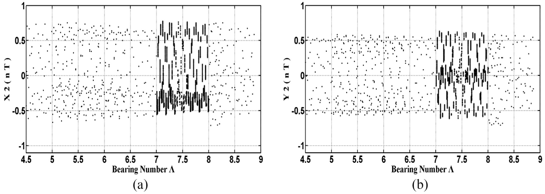
Bifurcation diagrams of the rotor center with different bearing numbers Λ: (a) X(nT) and (b) Y(nT).

The Poincaré sectional view of the rotor center with different bearing numbers: (a) Λ = 4.5, (b) Λ = 5.01, (c) Λ = 6.44, (d) Λ = 7.01, (e) Λ = 8.01, and (f) Λ = 8.29.
Dynamic behavior of the rotor center for bearing numbers 4.5 ≤ Λ ≤ 9.0.

Conclusion
The objective of this study was an analysis of the dynamic behavior of a rotor supported by a BPAB system. Analysis was then conducted on the orbit data to generate bifurcation diagrams and Poincaré maps. This showed that the orbits of the rotor center change along with the mass, and bearing numbers synchronously generate complicated motion which includes normal and sub-harmonic vibration, as well as periodic, and quasi-periodic. From the above numerical results, it can be seen that the hybrid method studied in this article has good convergence and is applicable to a gas bearing system. The trajectory of the system can be effectively calculated for either the rotor mass change or an increase in bearing number. For the influence of rotor mass, BPAB system behaves quasi-periodic motion under these three intervals of 0.01 ≦ mr < 0.033, 0.257 ≦ mr < 0.269, and 0.289 ≦ mr < 0.298. For the effect of bearing number, bearing system occurs in non-periodic motion only in 7.01 ≦ Λ < 8.01. It is important to avoid these four unstable conditions and guarantee the BPAB system to maintain stable situation. The results can also be the guideline for designing the BPAB system in the future.
Footnotes
Handling Editor: Stephen D Prior
Declaration of conflicting interests
The author(s) declared no potential conflicts of interest with respect to the research, authorship, and/or publication of this article.
Funding
The author(s) disclosed receipt of the following financial support for the research, authorship, and/or publication of this article: The authors gratefully acknowledge the financial support provided to this study by the Ministry of Science and Technology of Taiwan under grant numbers MOST-105-2221-E-167-010 and MOST-105-2622-E-167-007-CC3.