
Abstract
In this paper, the authors present the performance analysis of a Vertically Offset Overlapped Propulsion System (VOOPS)-based quadrotor in an aerial mapping mission. The dynamic model of the VOOPS quadrotor with the effect of overlapping propellers and the profile drag has been derived and simulated. A path-tracking mission is taken as an example for aerial survey. The controller used for this task is presented, followed by the response study of the attitude and the position controller with standard test inputs. A graphical interface has been built to select the area to be mapped by defining a polygon around it, and waypoints for lawn-mower type survey grid were generated based on the direction of wind. The path-tracking algorithm is presented along with course correction and simulations were performed with both conventional and VOOPS quadrotor. An experimental vehicle based on the proposed VOOPS concept has been built, tested on the same path, and the results are discussed. The results show that the VOOPS quadrotor is capable of performing the aerial mapping mission with quick response and good accuracy.
Keywords
Introduction
Aerial robot systems are primarily being developed for military applications like surveillance, reconnaissance, and mapping. Geomatics (the branch of science that deals with the collection, analysis, and interpretation of data relating to the earth's surface) is another area where aerial robots are finding wide applications. This is due to the price drop of unmanned aerial vehicle (UAV) components and development of advanced hardware.1,2 The low-cost navigational systems and the current development in UAV platforms along with light-weight, high-resolution cameras have enabled surveying sector to use such technologies. 3 It is definitely a replacement to the classical ground-based methods which are time consuming. Satellite imagery has an advantage of large area coverage but it lacks resolution. Although conventional remote sensing using manned aircraft has great advantages like better resolution, large coverage and capability to carry high-resolution cameras, UAV platforms can provide better resolution and make the mapping process economical and easy due to the advantage of being able to fly closer to the ground. They are a very important requirement when a small area has to be surveyed with centimetre level accuracy, where the manned aircraft or satellite imagery cannot attain the level of resolution that a UAV-based system can achieve. The resolution of the maps generated by aerial mapping depends on the resolution of the camera equipment used to shoot the images and the height at which the camera shots were taken. If the imaging is done closer to ground the shutter speed and light gathering capability of the imaging equipment becomes important. This is to have enough light and avoid motion blur. This demands for a slow and low-flying UAV where fixed-wing-type UAV’s are not an option. Hence one has to look at a VTOL (Vertical Take Off and Landing)-based UAV. Multirotor is the best option as they are more reliable than single rotor UAV’s. The quadrotor UAV’s for a given size suffers endurance and payload limitations and even a small improvement will help in carrying better camera equipment and cover larger area. The design of compact VTOL UAV with an improved endurance and payload capability is challenging as they are conflicting design requirements. Some research work to improve endurance such as, downward mounted propellers configuration,4,5 decoupling of the stabilization and the lifting tasks,6,7 discarding consumed batteries, 8 etc., were reported, but there was not much focus on the design modifications. Designing a quadrotor with high payload capacity and endurance for a given footprint is onerous and demands novel design approach. A novel concept of overlapping propellers at different planes for a quadrotor system was proposed by the authors in 2015, named as Vertically Offset Overlapping Propulsion System (VOOPS), 9 inspired by the tandem rotors configuration found in Piasecki HRP Rescuer. 10 The main objective here was to accommodate larger propellers by making design changes in the conventional quadrotor-based VTOL system. The propellers are allowed to overlap by placing them at different planes separated by a distance in such a way that they do not interfere with each other. The utility of VOOPS for aerial mapping applications is analysed in this paper. The design details of VOOPS and its mathematical modelling are presented in the beginning followed by issues related to aerial mapping using quadrotors, and the design of controllers for the mapping mission. Sections on simulation studies and aerial mapping present the simulation and experimental results of aerial mapping using VOOPS quadrotor and the advantages VOOPS offer.
VOOPS concept
As the name suggests, Vertically Offset Overlapping Propulsion System is a design concept where the propellers are vertically offset to enable overlap as shown in Figure 1. This design concept when implemented improves endurance and payload capacity without affecting the footprint, which was not feasible using a conventional quadrotor design. 11
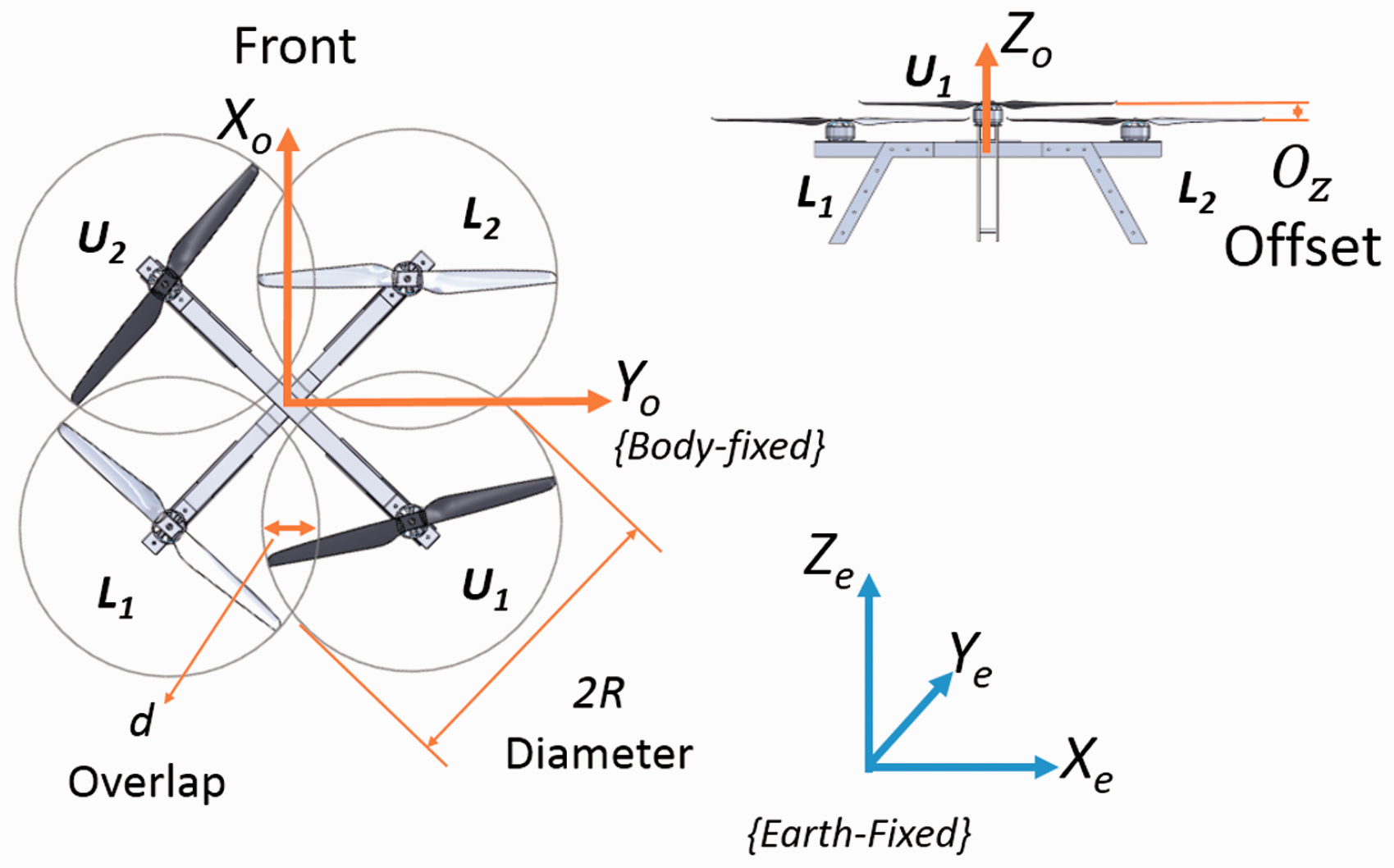
VOOPS configuration.
VOOPS is designed as a bi-layered frame, with the layers offset by a distance ‘
Mathematical model
Dynamic model
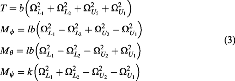
The dynamic model of VOOPS quadrotor can be derived using Lagrangian/Newtonian mechanics as given below. The rotational dynamics can be represented as

The translational dynamics can be represented using equation (2). Here,

Aerodynamic model
In this section, the aerodynamics of the propeller in the overlapped region is discussed, followed by the model of profile drag experienced by the quadrotor.
Model of an overlapping propeller
Based on the Blade Element Theory (BET), the forces acting on each elemental section are integrated along the span to find the net aerodynamic forces. 14
Consider one blade of the rotor at an angular position, shown as LN in Figure 2, LM is the region close to hub not affected by the inflow, MN is the region affected by the inflow from the upper propeller. The points M and N will vary depending on the overlap percentage and the position of the propeller, and the distance LM is defined as


Schematic representation of blade overlap.

Thrust loss in lower propeller.
It is seen that for a non-zero angular velocity of the lower propeller the loss in thrust increases as either of the upper propeller’s angular velocity increases. The maximum loss 15 is around 25% (∼4.41 N) at peak angular velocity (6600 r/min) of all the three rotors and at a normal operating angular velocity (3300 r/min), the loss is seen to be less than 5% (∼0.98 N).
Profile drag
It is straight forward to estimate the drag force,


Payload and battery capacity
For an aerial mapping mission, the flight time and payload capacity are crucial and the significance of having VOOPS configuration in achieving a higher payload/endurance is discussed in this section. The flight time of a quadrotor system is dependent on the payload and the battery capacity. This is because the collective upward thrust of the system will increase to maintain flight and hence the power consumption increases. As the available energy of the system is limited by the battery capacity
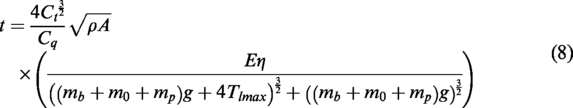
The flight time is calculated by

Battery capacity, payload and endurance.
VOOPS quadrotor specification.

VOOPS: Vertically Offset Overlapped Propulsion System.
Optimal battery capacity, 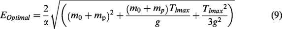
It is very important to choose the motor and propeller so as to perform flight with a total mass of
Aerial mapping
To map a region, the UAV has to fly in a specific pattern and take pictures. A typical image-based aerial surveying with an UAV platform requires ground control points (GCPs) or an accurate RTK (real-time kinematic)-based GPS (global positioning system) position measurement for geo-referencing purposes. The required ground sample distance (GSD) and the on-board digital camera are to be selected based on the mission requirements. With the intrinsic parameters of the chosen camera and the GSD the mission’s flying height is derived. The camera perspective centres (‘waypoints’) are computed based on the desired overlap of the images. Missions for detailed 3D model generation usually require high overlaps between images at low-altitude flights. The waypoints are given to the path-tracking controller which will ensure that the mission plan is executed. A stable UAV with good payload capability and endurance is required for this kind of mission. Also, the size of the UAV has to be minimal and man-packable. 18 A quadrotor vehicle is chosen here due its VTOL capabilities and the ability of the quadrotor to fly slow and closer to the ground. Being closer to ground and having a high-resolution camera will improve our GSD. VOOPS is the best option in this case as it has better endurance and payload capability when compared to the quadrotors of the same class.
Experimental VOOPS quadrotor: design specifications
VOOPS-based quadrotor system was designed to carry a camera payload and a gimbal. The total mass of the payload was estimated to be ∼0.3 kg. The frame of the proposed VOOPS quadcopter was built using hollow aluminium frame as shown in Figure 5 had a mass of 1.3 kg. A 6-cell lithium polymer battery was chosen as the power source.

VOOPS, experimental vehicle.
Using the equation (9) the battery capacity was estimated to be 25.79 Ah/572.54 Wh, which will have a mass of 3.1593 kg. The closest battery available was with a capacity of 26 Ah/577.2 Wh, which weighed 3.185 kg from Gens Ace™. To carry a mass of
A 400 Kv (Kv-Speed constant) BLDC motor (MN4014) from T-motor™ was chosen with the help of the xcoptercalc™ (a software to find the efficiency of a motor-propeller combination). The combined motor-propeller efficiency was calculated to be 83.3% and measured to be ∼81.6%. Based on the maximum current consumption of the motor at peak r/min, electronic speed controller were chosen. Expected flight time with the current setup can be computed from the equation (8) and it was found to be approximately 45 min.
Controller design
The VOOPS quadrotor for the mapping mission requires a controller for stabilization and path tracking. A cascaded control approach is chosen here, where the path tracker, which contains a path generator, a course correction, and a position controller, feeds the set points to the attitude controller. Figure 6 shows the overall controller architecture.
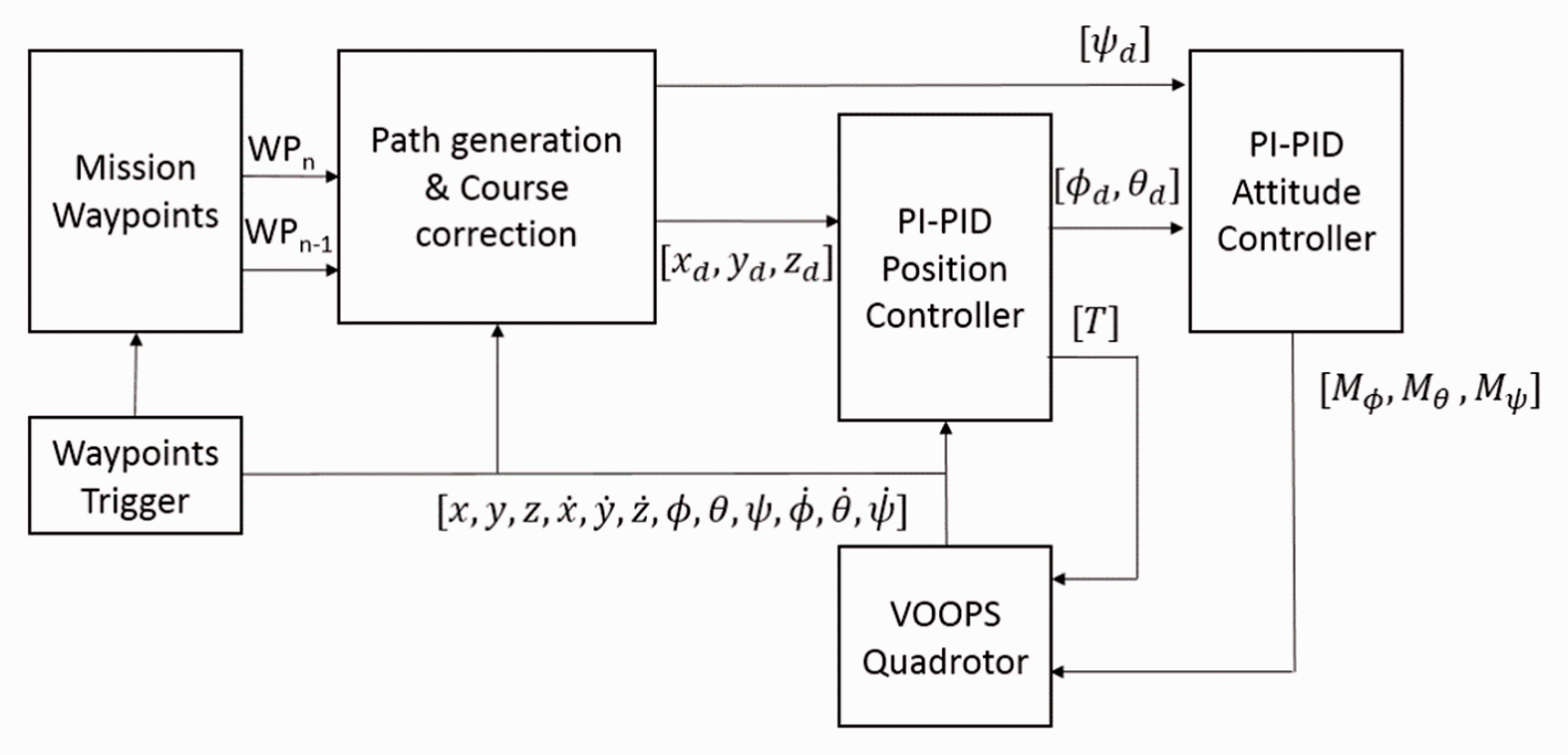
Path tracker control architecture.
The position/attitude controller is a cascaded PI-PID controller.
19
The inner PID loop is a velocity loop which resists the change in linear/angular velocities. This is achieved by comparing the desired rate of linear velocities/angular rotation with the GPS/gyroscope data. This makes the quadrotor stiff and reluctant to change in position/attitude. The outer PI loop controls the linear/angular position of the quadrotor which helps it position-hold/stabilize and compensates the drift in the inner loop due to the sensor noise and other disturbances. The implementation of the PI-PID controller for position and attitude are similar except the fact that the rotation matrix,
20

Position controller – Block diagram.
The gains were tuned for the inner loop first, followed by the outer loops. Ziegler–Nichols method 21 was used to tune the gains. The same gains were used in the experimental vehicle.
During the aerial mapping mission, it is important to maintain the path points in order to capture camera images at all the camera trigger points. To correct any deviation of the quadrotor from the desired path, a course correction algorithm has been implemented that directs the quadrotor back to the commanded path. 22
The algorithm can be explained with the help of Figure 8.

Path tracking and course correction illustration.
Mission planner
Mission Planner is a Graphical User Interface (GUI) developed to help the user choose the area to be mapped. The path-tracking controller requires the waypoints as input and it is impossible for the user to specify all the waypoints for a lawn-mower pattern. The authors have developed a GUI where the user can select an area of interest by specifying the vertices of a polygon. The mission planner takes into account the flight height, overlap, and the camera parameters to provide the waypoints for the lawn mower pattern. It is also equipped to take the direction of wind into consideration to modify the pattern such that the effect of the wind does not hinder the aerial survey process. Mission planner GUI is briefly explained in this section.
The map of the required area is taken in as a geo-referenced image into MATLAB™ using Google maps API™. The image obtained is centred about the home coordinates

Area of interest polygon.
To align the scan lines along the wind direction (shown by dark arrow), the home coordinate frame placed at waypoint 0 (WP0) needs to be rotated about its origin as shown in step 2 in Figure 9. Then the distances between the scan lines is constructed based on the requirements of the mission such as the height, the required overlap of images, and the resolution of the images. The generated scan lines are straight lines between two waypoints and are lawn-mower like pattern and alternates between the sides of the polygon along the wind direction as shown in step 3 in Figure 9. At each intersection with the polygon, the points are recorded (waypoints 0-8). However, the waypoints are required for the original polygon. The home coordinate frame is rotated back (to the initial orientation) as shown in step 4 in Figure 9, and the final waypoints (shown in square boxes) are for tracking the area. Given the percentage of image overlap needed, the height at which quadrotor is flown, and the camera parameters, the distance between subsequent parallel paths can be found out using equation (10)

Simulation studies
Numerical simulations were performed using the mathematical model to compare the behaviour of the VOOPS quadrotor with the conventional quadrotor 11 in aerial mapping applications, as well as to check the performance of the controllers. Simulations were carried out using MATLAB – Simulink™. To keep the comparison fair the battery used, frame weight and the motor were the same in both the quadrotors. 11
Attitude control
In order to simulate the performance of the attitude controller in maintaining the desired attitudes of the quadrotor, a series of inputs on pitch axis, as explained below, were given to change the pitch of quadrotor.
A sinusoidal variation of pitch with peak to peak of 45°. A pulse of 22.5° and 45° for a duration of 4 s each. An impulse at time t = 25 s.
The results of the simulation for VOOPS and a conventional quadrotor (same overall size as VOOPS, with non-overlapping propellers) are shown in Figure 10.

Simulated response for the given inputs.
It is found that both the quadrotors were able to follow the sinusoidal and pulse inputs with a slight lag due to the system inertia. The impulse signals are generally difficult to be tracked and can be used to predict the responsiveness of the system. From Figure 10, VOOPS seems to have a better performance than conventional quadrotor owing to its faster response to commanded inputs. Better response is also seen in the case of step inputs where the VOOPS is able to achieve the set point earlier than conventional quadrotor. Although the rotor inertia of VOOPS is expected to be slightly higher due to the larger propeller, it is able to better track the input signal. This is due to the force benefits of a larger propeller, which is significant than the rotor inertia differences of the propellers.
Position control
Position control performance was simulated for position hold as shown in Figure 11. Both the quadrotors were able to hold the position with minimal errors as shown in the results in Figure 12(a). In order to study the effect of wind on position hold, a uniform wind velocity of 15 m/s, 45° about

Simulated response for wind disturbance. (a) Position; (b) Attitude.

Normal distance error and power consumed. (a) Normal distance error; (b) Power consumed.
The error graphs in Figure 12(a) show that the maximum error made by the conventional quadrotor happened on the onset of wind which was sudden at 5th second. The VOOPS, being a more capable copter due to its 15 inch propeller system, was able to handle the sudden wind with very minimal deviation as compared to the conventional quadrotor. The overall error characteristics show that the VOOPS is definitely having an advantage over a conventional quadrotor. The major effect is seen in the power consumed, as shown in Figure 12(b), where the conventional quadrotor consumes almost 68% more power than the power consumed by the VOOPS quadrotor. 11
This is due to the reason that the conventional quadrotor operates at a very high rotor speed to maintain altitude whereas the VOOPS can produce the same force more efficiently at lower rotor speeds due to the benefits of larger propeller.
Path-tracking control
Dynamic simulation of VOOPS quadrotor and a same-size conventional quadrotor was carried out using the waypoints as shown in Figure 13(a). Waypoint 0 was set as the home point from where the launching and landing were implemented. There were eight waypoints and between two waypoints straight line path was implemented in the controller. The yaw angle was maintained towards the next waypoint throughout the mission and the coordinate frame was centred on the first waypoint.

Simulated path: conventional vs. VOOPS. (a) Tracked path; (b) Close-up view of tracked path at WP:2.
Figure 13 shows the simulated path of the quadrotor. It is seen that the VOOPS quadrotor is able to track the path better and with lesser over shoot than conventional quadrotor. The error shown in Figure 14(a) is the normal distance error between the desired and actual point for the complete mission. In both conventional and VOOPS quadrotor, the error seems to peak during the turn. This is due to the reason that the quadrotor has to stop from a forward velocity then take a turn. In Figure 14(b), the error at waypoint 2 is shown in detail. The error at sharp turns as well as the overall tracking error are high for the conventional quadrotor. In all the simulations, the controller gains were tuned using the optimizer available in MATLAB™.
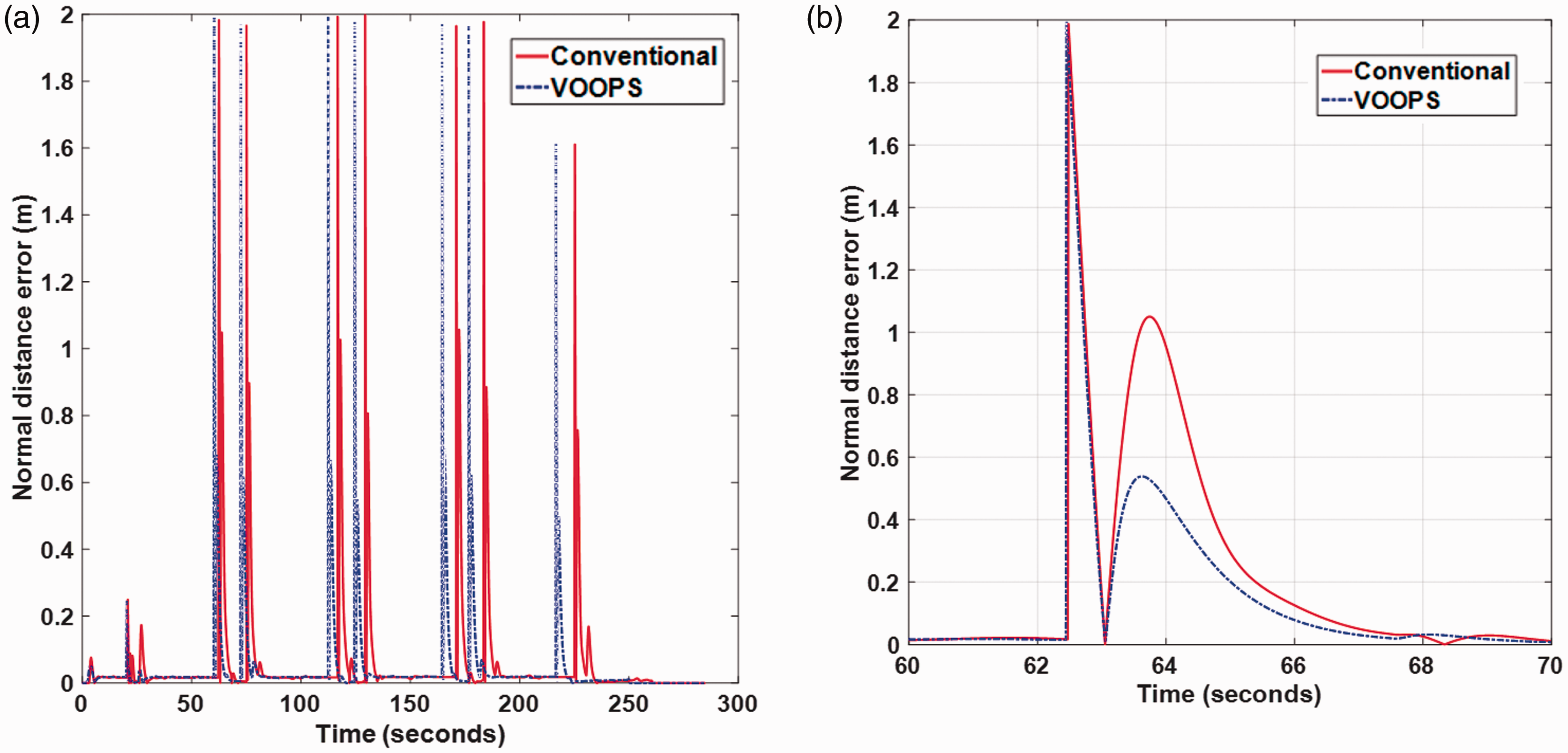
Tracked path errors conventional vs. VOOPS. (a) Error for full mission; (b) Error at waypoint no. 2.
The simulation results shown above confirm that VOOPS quadrotor was able to respond faster compared to the conventional quadrotor. This can also be seen from Figure 15 which shows the linear and angular velocity variations of both the quadrotors at waypoint 2. It is seen that both the quadrotors were travelling towards the waypoint till 63rd second and the quadrotor tried to decelerate by pitching near waypoint 2 as shown in Figure 15(b). The way in which the forward velocities are modulated, the overshoots, and the response of the VOOPS quadrotor are better than the conventional quadrotor.
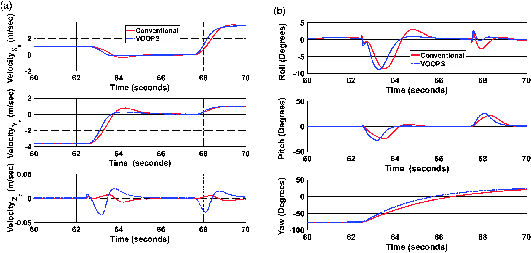
Linear velocities and the attitude at waypoint no. 2. (a) Linear velocities; (b) Attitude.
The efforts involved in stopping at the waypoint, changing the heading, waiting for a specified time, and then accelerating forward towards next waypoint are shown in Figure 16. The VOOPS quadrotor is quick in generating the required moments and forces. Due to this, the overshoots are minimal and better tracking is noticed as seen in Figures 13 and 14. The Force

Forces and moments at waypoint no. 2. (a) Moments; (b) Forces.
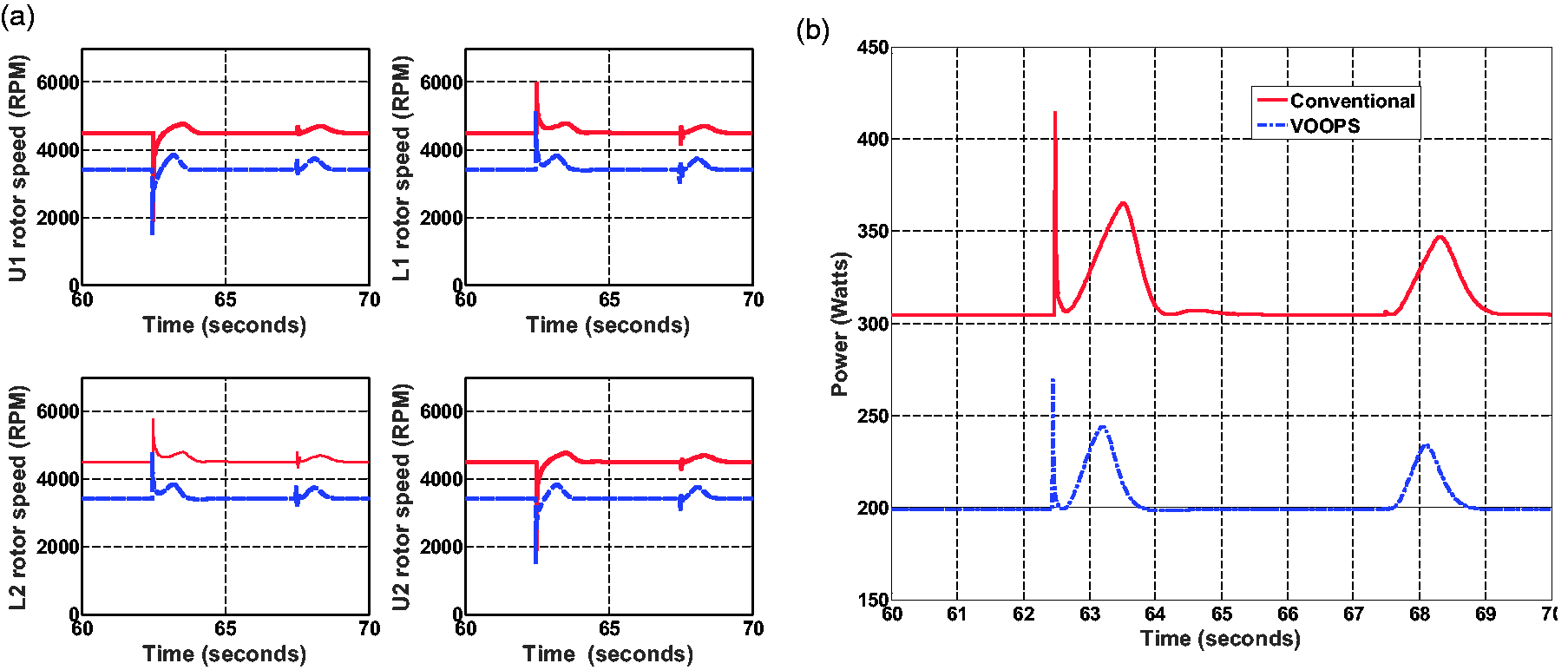
Rotor r/min and power consumption at waypoint no. 2. (a) Rotor speeds; (b) Power consumption.
The power consumed by both the quadrotors are shown in Figure 17(b). The conventional quadrotor consumes more power due to the demerits of smaller size of the propeller. The propellers in the conventional quadrotor spins almost 1500 r/min faster than the VOOPS quadrotor to produce the same amount of thrust as shown in Figure 17(a). It can be also inferred from the graphs that the corners are the most power demanding portions of the path.
One of the drawbacks of VOOPS is the loss of thrust due to overlap. Figure 18 shows the losses incurred during the mission for VOOPS system with the specifications discussed in given in Table 1. The figure shows that the loss at waypoints is on an average 3% and the maximum loss of 7.5% occur during the take-off. It is also noticed that during hover the loss is around 2.5% and the loss at the waypoints are slightly higher due to pitching/rolling, where the altitude controller spins up the rotor’s to maintain height during pitch/roll and this increases the loss as shown in Figure 3.

Loss due to the overlapped propellers.
Aerial mapping: Experiments with VOOPS quadrotor
The VOOPS quadrotor shown in Figure 5 was used for the aerial mapping experiment. A playground was chosen as the area to be mapped. Figure 19 shows the area being mapped and the path generated using the GUI. The starting point, way points and the coordinates are marked in the figure. Experimental results are discussed in the following sections.

Planned path for aerial experiment.
The distance between the tracks,

VOOPS quadrotor in flight.
Path-tracking experiment
Experimental VOOPS quadrotor was made to track the path and the tracking results are shown in Figure 21. A path error threshold,
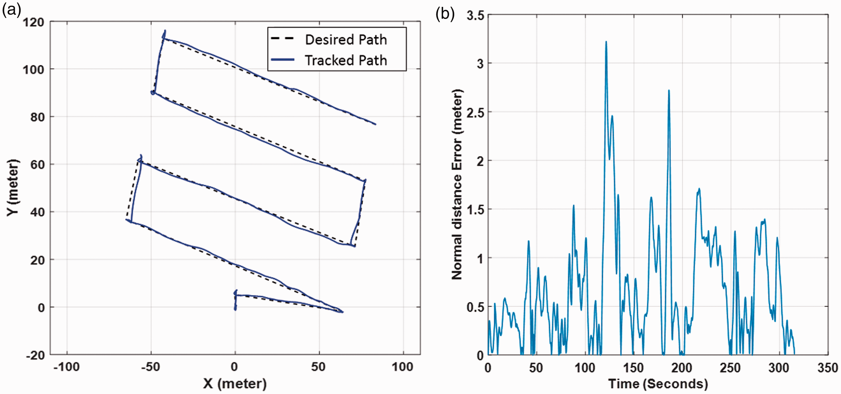
Experimental results. (a) Tracked position of experimental; (b) Deviation from the track.
The experimental deviations are mainly due to the sensor noise, wind disturbance and the GPS inaccuracies which were not considered during the simulations. It was found that the quadrotor was capable of tracking the planned path and the maximum tracking error was found that the quadrotor was able to operate within the allowed tolerance.
Aerial survey results
The aerial mapping was carried out using a camera having horizontal and vertical field of view as 94.4° and 122.6° respectively. The shutter speed, ISO, and aperture was set on automatic mode during the course of the mission. However, if the images have too much blur or noise, the parameters need to be manually tuned and set accordingly. For obtaining high-quality results, the maximum overlap of images is required. The desired overlap between the images was given as 35% and the desired GSD was 2 cm/pixel. For the given inputs, the desired height for the mission (15 m) was calculated, based on the camera parameters, using the equation:

Sample images taken by the quadrotor.
This information can be obtained either through geo-‘location using a GPS logger directly or indirectly by providing GCPs. If neither of the information is provided, the model obtained will have no scale, orientation, and absolute position information. As a result, no metric information of the terrain can be retrieved such as the area of a particular patch of the terrain, volumetric information or distance measurements. Here GCPs were used for geo-referencing. Figure 22 shows few images and Figures 23 and 24 show the processed results, as an example. The camera centres are first estimated (shown as camera field of view and position) and the point cloud (collection of 3D points) is generated by the software using key point observations/features from overlapping images shown in Figure 23.

Point cloud data.

Meshed model.
Inadequate overlap of images may lead to holes in the point cloud and therefore a lesser number of 2D key point observations. To overcome this, the entire point cloud is meshed as tiny triangles to fill the spaces. The image data is overlaid on top of the meshes to make the scene look close to real as seen in Figure 24. The entire model is ortho-rectified and the orthomosaic is shown in Figure 25.

Stitched ortho-rectified image.
Conclusion
This paper presented a novel quadrotor design and its usefulness in aerial mapping missions. Improved dynamic performance and better endurance are the two main advantages of using VOOPS in aerial missions. Payload and endurance advantages of VOOPS were discussed and compared with the conventional quadrotor of the same class and VOOPS was found to be advantageous in all aspects. Also, the choice of the battery for best flight times was discussed. The position and attitude controllers used for this purpose were discussed and tested with the dynamic model of VOOPS and also compared with conventional quadrotor. A path tracker has been developed which consists of a path generator and course correction. VOOPS and conventional quadrotor were studied during position hold with wind disturbances. A simple user interface was developed for scanning the area of interest. Simulations were carried out to analyse and compare the performance of VOOPS quadrotor with conventional in an aerial survey mission. Path-tracking experiment was conducted with the VOOPS vehicle. The path-tracking results and the aerial survey results are discussed. VOOPS has shown superior performance and best suitable for aerial survey applications.
Footnotes
Declaration of conflicting interests
The author(s) declared no potential conflicts of interest with respect to the research, authorship, and/or publication of this article.
Funding
The author(s) received no financial support for the research, authorship, and/or publication of this article.