
Abstract
Small unmanned aerial vehicles are widely used in urban space because of its flexibility and maneuverability. However, there are full of dynamic obstacles and immobile obstacles which will affect safe flying in urban space. In this paper, a novel integrated path planning approach for unmanned aerial vehicles is presented, which is consisted of three steps. First, a time-environment dynamic map is constructed to represent obstacles by introducing time axis. Second, unmanned aerial vehicles’ flyable paths are explored based on breadth-first algorithm. Third, a path planning method using A* algorithm and local trace-back model is designed in order to discover sub-optimal feasible path rapidly in unmanned aerial vehicles’ field of view. Finally, the simulation results have illustrated that the proposed method can ensure unmanned aerial vehicles’ autonomous path planning safely and effectively in urban space crowded with obstacles.
Introduction
Since unmanned aerial vehicles (UAVs) have great potential to complete missions without human intervention, 1 large number of applications of UAVs for both military and commercial purposes have been emerged. However, in the urban space, the UAVs usually encounter with various obstacles, such as buildings, electrical wires and other flying UAVs, which may affect UAVs’ safety. Therefore, designing a safe as well as flyable path for UAVs in the environment crowded with obstacles is needed.
In recent years, many approaches about path planning have been investigated for UAVs. McLain and Beard 2 constructed a Voronoi diagram based on the known locations of threats to generate an initial path and then took different combinations of the edges so as to choose the lowest-cost flyable path. As pointed out by Wang et al., 3 this approach did not take the threats’ effective range into consideration, and thus a UAV may go through some of the threat zones. Wang et al. developed a path planning method, which built a Laguerre diagram based on Delaunay graphs, to overcome the drawbacks of Voronoi diagram. The graph-based methods such as Voronoi diagrams,2,4,5 Laguerre diagram3,6 or visibility graphs 7 all assume that the entire environment remains unchanged when a UAV is flying, so that a safe path from start-point to end-point can be designed according to the collected environmental information. However, it is inaccessible to obtain reliable information of the entire environment, for instance, pop-up obstacles will never be localized in advance until a UAV is approaching them. 8 Thus, the traditional graph-based approaches can hardly meet the requirements of planning a safe path in dynamic environment.
It turns out that UAVs must have the ability to deal with new obstacles that burst into environments. Furthermore, there are many works in the literature dealing with path planning for UAVs in dynamic environments, such as A* and D* algorithms,9–11 potential fields, 12 model predictive control 13 and evolutionary algorithmic techniques.14,15 Many efforts have been made in the field of UAV path planning, and these approaches can be mainly classified in two thoughts:
Assuming that the number of obstacles is limited and obstacles are far from each other so that a safe path can be easily designed.2–7 This assumption is not suitable for urban environments because irregular obstacles are densely placed in the environment. Thus, flyable areas are limited.
Calculating the obstacles’ probability of occurrence at some points in the future via dynamic prediction algorithms so as to plan a path without obstacles for UAVs.16,17 However, these methods highly depend on the accuracy of location and the efficiency of algorithms, and thus are not practical for real-time path planning in the dynamically changing environments.
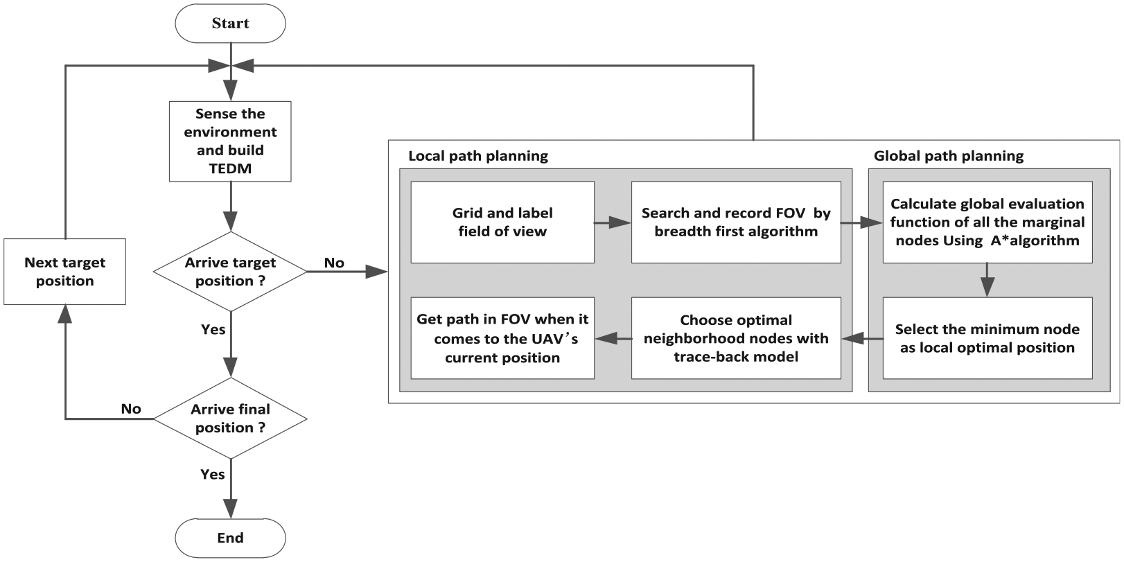
In this paper, we propose a collision avoidance algorithm focusing on dense and static threats in uncertain environments. 18 In order to plan a safe flyable path in urban space crowded with irregular buildings and moving obstacles, we introduce a time axis to the collision avoidance algorithm. In this manner, the environments where UAVs fly are extended to time-environment dynamic map (TEDM). Based on TEDM, we designed an integrated approach which combines breadth-first algorithm, A* algorithm and local trace-back model to plan an optimal path in each short time interval, thus avoiding irregular buildings without simplification. Our proposed method is detailed in the following sections.
Problem statements and UAV modeling
Problem statement
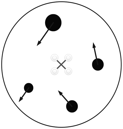
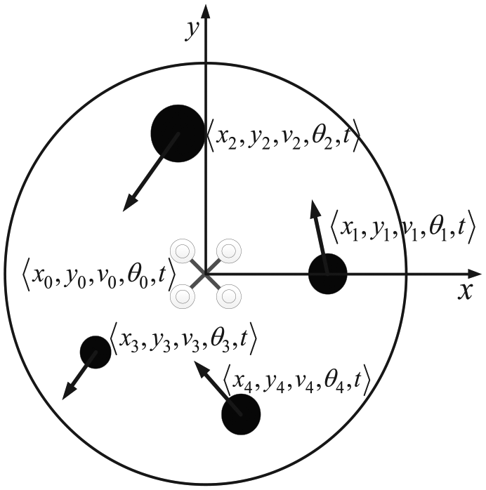
With popularity and proven success of UAVs in various situations, the demand of UAVs used in urban space is increasing. The remarkable character of urban space is that, as we all know, it is filled with obstacles which are irregular and hazardous, and the flyable region between buildings is restricted. To avoid flight-risks of obstacle collision, we design a novel path planning algorithm for UAVs in urban space crowded with irregular obstacles, which makes use of the cost function to build an optimal local trace-back model within the range of sensors. The dynamic obstacles in environment should also be considered, which is an enormous challenge for path planning in such a strict circumstance. Figure 1 depicts a representative urban space, in which the gray boxes indicate building obstacles, the black spots mean other dynamic UAVs which represent moving obstacles and the arrows mean the corresponding direction. Given such an environment, our mission is to plan a safe path for a UAV from the start position to the final position, which passes through the path from the target position 1 to the target position 2 sequentially. The red spots in Figure 1 stand for the target positions, respectively.
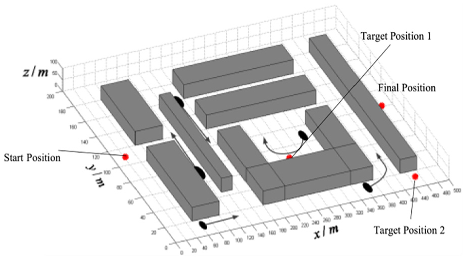
Sketch map of urban space crowded with obstacles.
UAV modeling
The results we present in this paper can be applied to different kinds of rotorcrafts. In this paper, we focus on quadrotor UAVs for it is an intuitive model that is often used in literature.
The key features of quadrotor aircrafts lie in its flexibility and maneuverability so it comes out that we do not need to think much about the restrictions of the minimum turning radius and the overload problem while turning. As a result, a four-rotor aircraft can be regarded as a controllable particle,
19
without considering the rotation around center of mass. So, the kinematic model of UAV is defined by its position
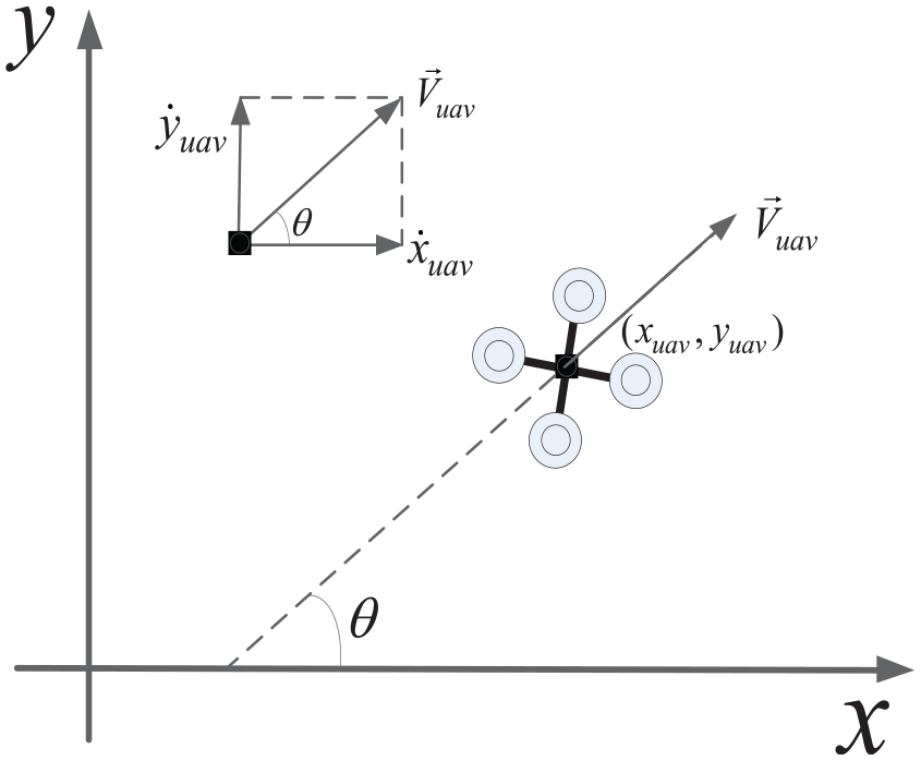
The kinematic model of UAV.
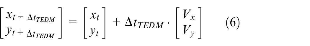
Therefore, the UAV’s kinematic equation is given by
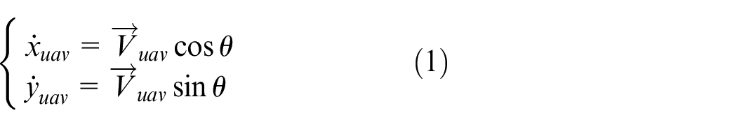
Note that
For convenience, many works assume that the UAVs maintain constant velocity;20,21 however, it is still not easy for UAV’s controller to compute because constant variables are often inestimable. Hence, the UAV’s kinematic equation based on particle is further simplified using gridding model. 18 As one can observe from Figure 3, a gridding model of UAV is able to move in eight geographical directions in case they are free.
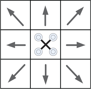
Gridding model of UAV.
Taking the factor into consideration that UAV needs to explore obstacles around to get information about the environment, we define the boundary of detected coverage as field of view (FOV, which is similar to the field we can see through our view). Let

Sketch map of FOV.
TEDM
We should avoid not only static but also dynamic obstacles while planning path in such a limited environment as illustrated in Figure 1; thus, a new approach is put forward using TEDM, aiming to fulfilling the demand of real-time path planning in harsh and special environments.
In order to simplify the static obstacles, a horizontal plane is chosen from stereoscopic space. As most of the buildings in urban space are vertical from bottom to top and their shape and position in horizontal plane are time-invariant, we can use two-dimensional space to replace three-dimensional space while constructing the model of static obstacles (see the gray regions in Figure 5).
Horizontal plane of urban space.
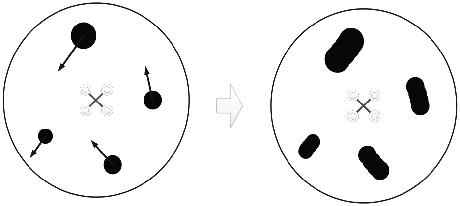
To moving obstacles (see Figure 5, the black area), time axis is introduced on the basis of the horizontal plane we built before to discretize the environment, forming a three-dimensional TEDM. It consists of state
which means
Time-environment dynamic map.
Path planning based on TEDM
Reasons for the methods
Traditional methods often regard obstacles are far from each other. They assume the obstacles are small and slow. When encounter with irregular obstacles, it is hard to simplify them. Furthermore, the fast dynamic obstacles require efficient algorithm. The A* algorithm can guide the UAV, but it often has a collision with irregular obstacles. The breadth-first algorithm always searches the entire environment to find the optimal path, causing a waste of calculating time.
We take the advantages of A* and breadth-first algorithms to solve the problems. The trace-back model is applied to find the optimal local path, purposing on reducing the time-consumption and improving the safety. Finally, the method for path planning based on TEDM is built, which can not only reflect to dynamic obstacles fast but also avoid collision into irregular obstacles.
Principium of path planning based on TEDM
Generally speaking, the purpose of path planning is to design a safe path for UAV; however, as we analyzed in section “Introduction,” the existing methods can hardly meet the requirements in such complex environments with crowded obstacles. As shown in Figure 7, an integrated approach can be planned as follows. First, we adopt the breadth-first algorithm to explore the surrounding environment and then find out an optimal waypoint in FOV with A* algorithm, and finally apply the trace-back model to plan an optimal path in each short time interval. In this way, we can get a path avoiding obstacle collisions over the urban space.
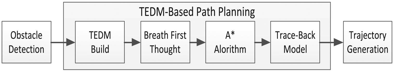
TEDM-based path planning system.
First, a global evaluation function is constructed by A* algorithm


where
Thus, the local environment in FOV can be depicted in TEDM, and the motion tendency of obstacles in FOV can be predicated in a short time interval
Then, the TEDM in FOV is gridded and each grid represents a minimum node when flying, so breadth-first algorithm is used to explore the environment in FOV. Given kth local cost function
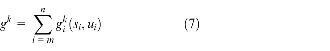
where m stands for the UAV’s node now, n means the number of nodes in FOV,
When the start node m is set, all flyable paths can be determined in FOV
where
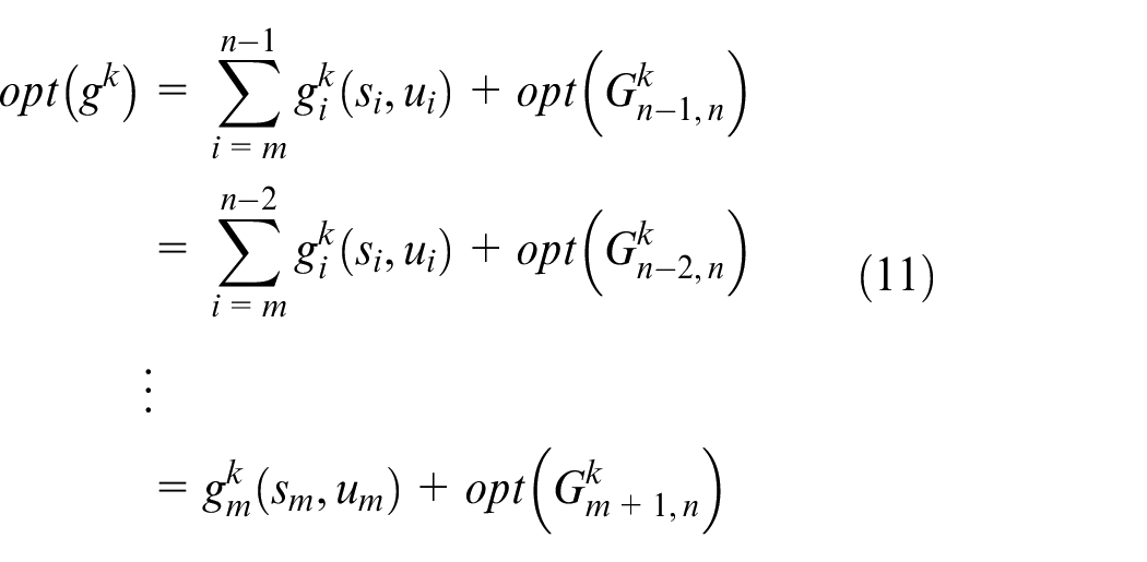
The breadth-first algorithm is used to compute the cost values of marginal nodes. When the decision-making process reaches FOV’s marginal nodes, the optimal evaluation function can be selected by choosing the minimum
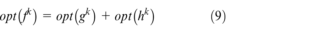
where opt is short for optimization, which means the minimum
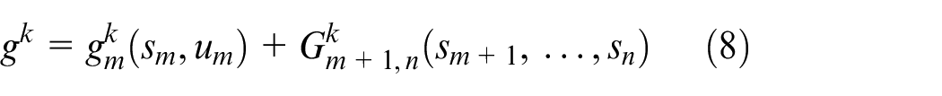
Take a step back from
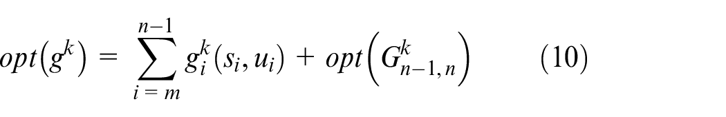
After equation (10), the optimal step
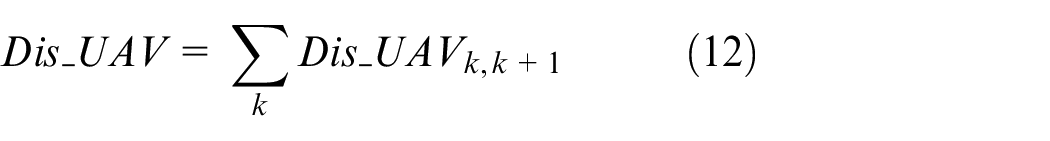
Finally, the above procedures are repeated until a safe path in the global urban space is obtained. The distance of the final path can be expressed as
Implementation of path planning based on TEDM
As described in section “Path planning based on TEDM,” the proposed method aims to plan an obstacle-free path using the TEDM in urban space, and that can be achieved as following five steps (Table 1).
Path planning step sequence.
TEDM: time-environment dynamic map; FOV: field of view.
As we discussed in section “TEDM,” all obstacles in FOV can be predicated in
Obstacle sensing by sensors onboard.
After translating the environment to TEDM, we grid the environment. The A* algorithm, breadth-first algorithm and trace-back model rely on grids to design the path. Therefore, we transfer the environment to a matrix at the beginning, and labeled 0 and 1 to the safe area and obstacles, respectively. To TEDM, the labels are as shown in Figure 9.
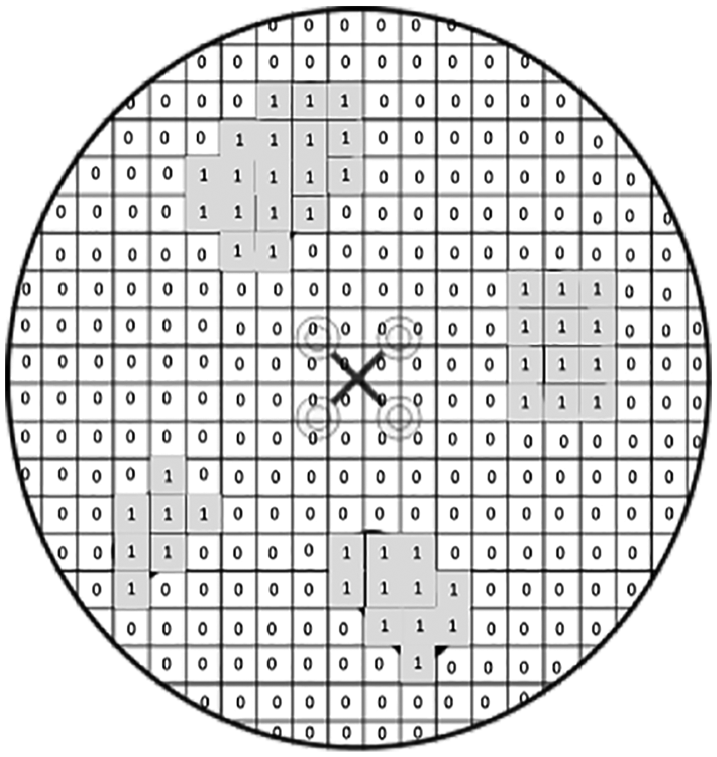
Grid map of obstacles in UAV’s FOV.
Then, breadth-first algorithm is used to explore and record all nodes in FOV from UAV’s start node, and for every node at the margin of FOV, the cost function is calculated to define the optimal margin node (see Figure 10).
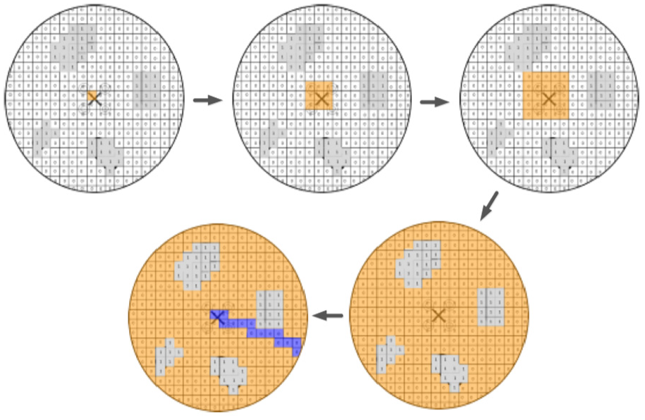
Explore and record environment based on breadth-first algorithm.
After that, an optimal node on FOV’s edge can be obtained using A* algorithm, and take a step back from this optimal node, then it is the second optimal node. Tracing back step by step, we can get the optimal path in FOV at t moment.
Finally, this integrated method is applied over the environment along with the position of target and then a safe flyable path can be designed to avoid collisions in the urban space crowded with different kinds of obstacles.
Figure 11 shows the functional architecture for path planning based on TEDM and illustrates how this integrated method operates.
Functional architecture of TEDM-based path planning.
Simulations and analysis
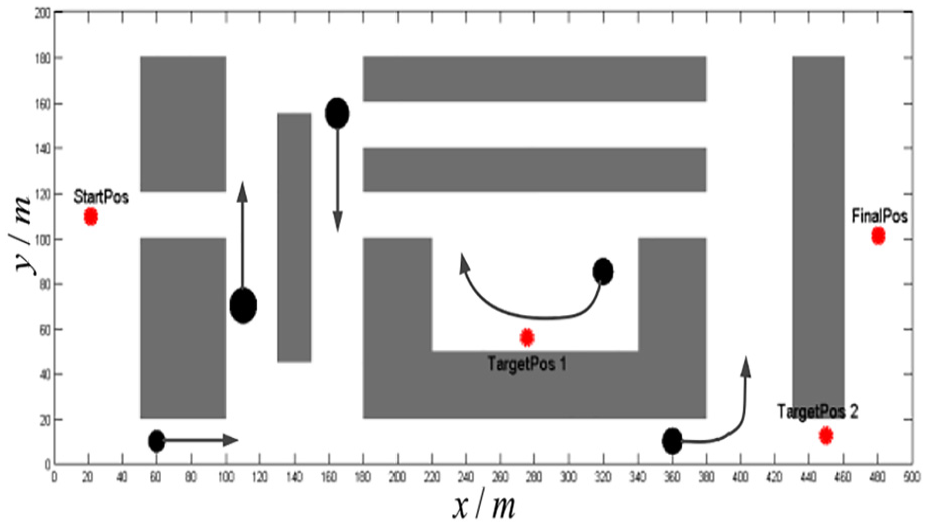
Suppose the complex environment in urban space is a rectangular with 500 m height and 200 m width, the of UAV velocity is 2 m/s, and its mission is to fly from the start (2, 109) position, with passing through the first target (76, 55) and the second target (450, 13), to the final position (480, 101). Figure 12 shows the simulated results.
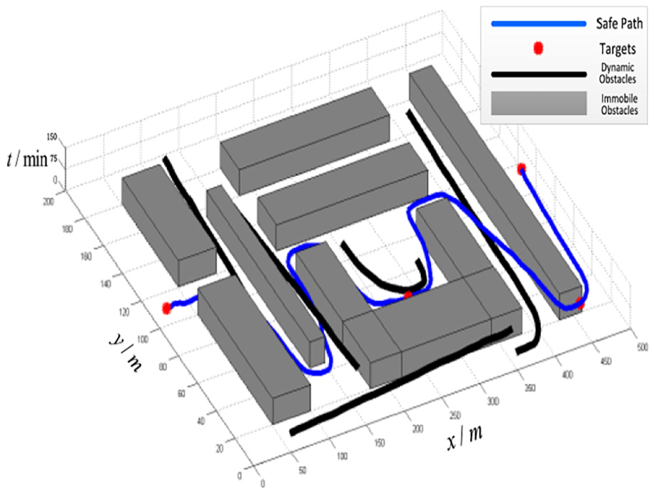
TEDM-based path planning.
To further depict the safety of the UAV, some flying moments are shown in Figure 13, where the brown disk stands for the FOV, and the gray blocks and the black spots represent static and moving obstacles, respectively.
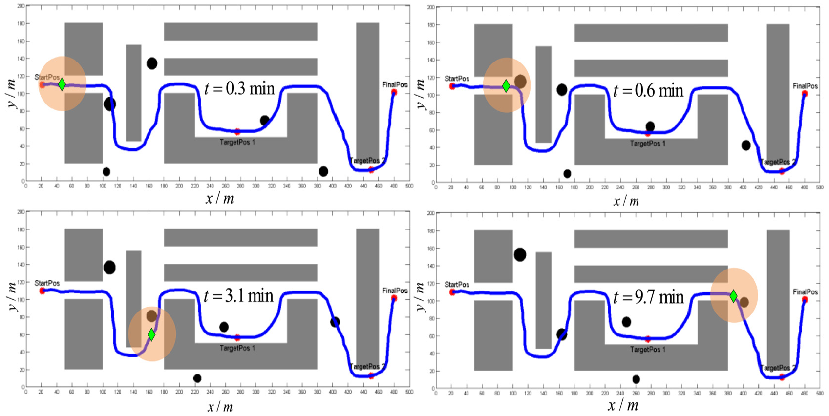
Some moments when designing path in urban space.
As shown in Figure 13, a safe path can be obtained with the method of TEDM. However, the effectiveness of TEDM is not discussed. So, we introduce A*- and Voronoi-based approaches to verify the effectiveness of the method of TEDM.
As shown in Figure 14, the TEDM algorithm performs well, but A* algorithm cannot arrive to the final position. Because A* algorithm tries to look for the final position and attempts to get an optimal path from the UAV to final position, and when there are threats between the UAV and final position, it will probably fall into dead zone.
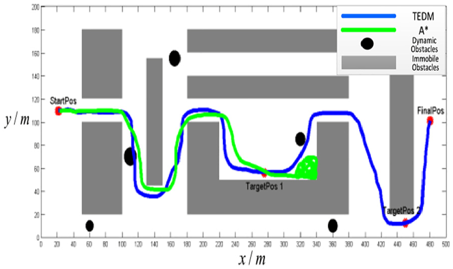
Path planning based on A* algorithm compared with TEDM.
In Figure 15, though the Voronoi graph can plan a path from start position to final position, but the path often goes through buildings. The TEDM algorithm can avoid crowded obstacles safely, and the path obtained by TEDM is smoother than Voronoi graph.
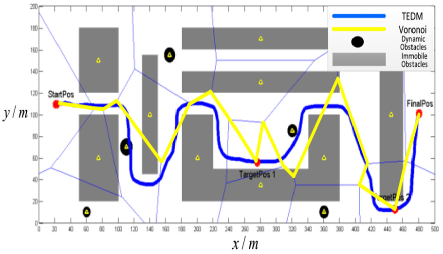
Path planning based on Voronoi compared with TEDM.
More detailed information can be found in Table 2. The results show that TEDM costs 14.8 min in getting a safe path, but the other two never arrive to the final position. To the average memory consumption, TEDM performs better than A* and Voronoi, which spends less than half memory consumption. To the UAV, the most important factor is safety; here, we use collision amounts to judge the safety. We can infer from Table 2 that TEDM has no collision, while A* and Voronoi get 1 and 14, respectively. The results show that TEDM has a better performance compared with the other two traditional algorithms.
Comparisons of A*, Voronoi and TEDM.
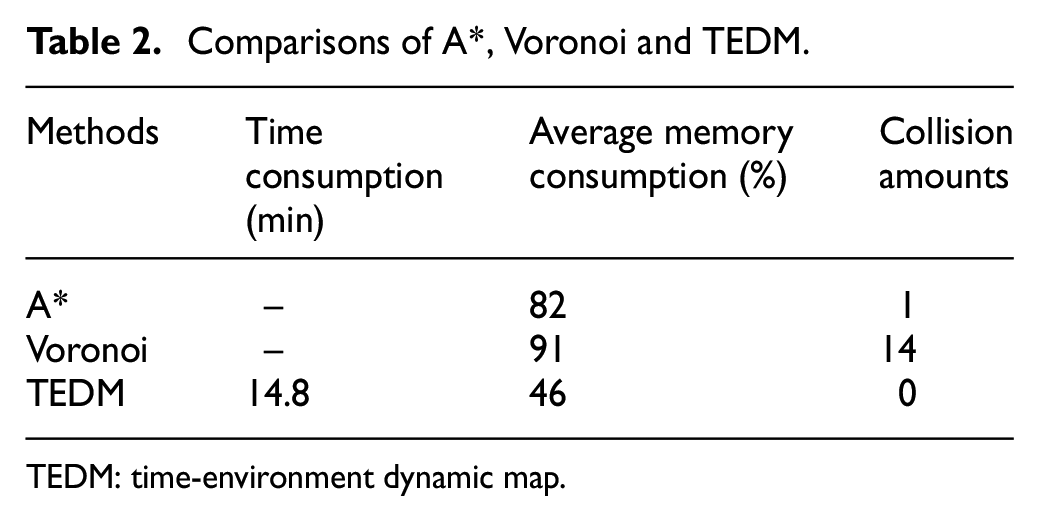
TEDM: time-environment dynamic map.
Conclusion
In terms of complex environment, we have argued how the UAV can avoid collision in urban space safer and faster. After reviewing the studies in the context of immobile and dynamic obstacles, a conceptual constructive model which combines A* and breadth-first algorithms has been proposed. Following are some concluding remarks:
A TEDM is built, which divides the whole target into two parts, global target and local target. A* and breadth-first algorithms are applied to global and local environments, which improve the safety in path planning.
Small time interval is introduced to transfer dynamic obstacles to instantaneous immobile obstacles, making it more efficient to avoid dynamic obstacles.
The proposed method can avoid irregular buildings without simplification, using A* algorithm to guide itself globally and breadth-first method to avoid local obstacles.
Still, there are several issues in need of attention and further investigations, including practical studies and the study on three-dimensional path planning.
Footnotes
Appendix 1
Declaration of conflicting interests
The author(s) declared no potential conflicts of interest with respect to the research, authorship, and/or publication of this article.
Funding
The author(s) disclosed receipt of the following financial support for the research, authorship, and/or publication of this article: The research was supported by the National Natural Science Foundation of China (grant nos 61503405 and 61703428) and National Aeronautical Science Foundation of China (grant nos 20160896007 and 20160896008).