
Abstract
This paper presents the trajectory planning of an under-actuated quadcopter unmanned aerial vehicle. To control the complete structure of the rotorcraft, the main model is divided into two sub-models, namely inner model and external model. The inner model is for the attitude control model controlled by the sliding mode controller and the outer model is altitude control model governed by the extended state observer. The quadrotor unmanned aerial vehicle is a type of multivariable, multi-degree-of-freedom and nonlinear in nature. Planning the trajectory of the unmanned aerial vehicle and stabilizing its flight are complex tasks because of its ability to maneuver quickly. Due to these stated issues, the tuning of this type of dynamic system is a difficult task. This paper deals with these issues by designing the aforementioned dual controller scheme. In addition, the effectiveness of the proposed controller is apparent in simulations performed in MATLAB, Simulink 2016. The designed controller shows better results and robustness than traditional controllers do.
Keywords
Introduction
In the last few years, the trajectory tracking and planning of quadrotors have developed considerably and have generated widespread interest in the study of quadcopter unmanned aerial vehicles (UAVs). This is because UAVs have the capability of taking off and landing vertically and can hover and maneuver at low velocities. It can also reach places like mountainous regions, which are difficult for humans to reach. The demand of reliable and stable hardware of the quadrotor type aircrafts for precision remote sensing has increased manifold. 1 These aerial vehicles are widely used for civilian as well as for military purpose. The UAVs are classified into two types, multi-rotor aircraft and fixed-wing aircraft.2–4 Rotorcraft UAVs have many advantages over typical aircrafts like, low weight, advance and unique design and simplicity in the structure of vehicle. The important features of rotorcraft UAV are greater mobility, low cost, ability to perform vertical takeoff and landing. In the current era, according to the demand of advance precision remote sensing the rotorcrafts are programmed for surveying and mapping. 5
In recent times, quadrotor UAV is emerging to be a well-known topic among scientists and academics for its ability to take off and land vertically, to hover and maneuver in difficult environments. In addition, it has major usages in many fields; for example, reconnaissance, product deliveries, trajectory tracking and infrastructure inspections. However, trajectory tracking of a quadrotor UAV is quite difficult in a dynamic environment while considering dangerously high altitudes and other limitations. Therefore, this paper tries to design a flight control algorithm that is robust and efficient even in a dynamic environment. It makes sure that the quadrotor UAV works fine despite the limitations of the environment.
This research chooses a quadrotor type model of rotorcraft just because of its precise altitude and attitude control. To simulate the model of UAV, the time response of the system is much longer when combined with control method of six degrees-of-freedom (6-DOF) model of UAV, the performance is not so efficient and the learning time is too longer. This research paper mainly focuses on trajectory planning using sliding mode observer and proposes a new attitude control architecture.6–8
The dynamic modeling of the quadrotor aircraft is studied by Chen et al. 9 The rigid body dynamic equations are used for the modeling of the quadrotor aircraft. However, a small literature is needed to provide practical methods for testing the model parameters. As the relationship between the aerodynamics and the propellers is quite complex, there is a demand for more precise equipment for testing.
Learning-based control methods are presented in Mod and Farid 10 and in Benosman et al. 11 it is based on fuzzy control, neural network adaptive algorithm and robust neural network control to design the quadrotor flight controller, although this type of controller does not require the motion model of the UAV but requires massive experiments and flight data to stabilize the system. This system has huge hardware requirements and there is little practical implementation of the system.
Different linear control methods as given in the literature works12–14 based on proportional–integral–derivative (PID) designed for the quadrotor attitude controller such as linear controllers which are relatively simple. Still, the controller performance will significantly decrease when the aircraft faces adverse conditions. Meanwhile, the researchers began to apply the control techniques to design the attitude controller for the UAV in Madni et al. 15 The core system is able to estimate the total disturbance of the real-time system, but not implemented in hardware. In Ali and Li, 16 a quadrotor-based model of an aerial vehicle along with a gripper attached to grab the wanted object for remote areas, hybrid adaptive controller is used to tackle the nonlinear behavior of the rotor craft.
Nonlinear control methods present in Razmi and Afshinfar 17 are based on feedback linearization and sliding mode control (SMC) design of the UAV controller. Such control techniques depend on accurate model parameters. On the basis of model parameter, the quadrotor performance and flight range can be enhanced because the SMC has better robustness. This type of controller does not interface with the system for real-time observation and the control effect is not ideal when the interference is large.
This paper presents a quadrotor trajectory-planning algorithm based on sliding mode and extended state observer (ESO) design for the control characteristics of UAV aircraft. To implement the designed algorithm, sequence of experiments is designed to obtain the modeling parameters then the control of three attitude angles of the quadrotor is analyzed by SMC and ESO, the flutter phenomenon which exists in SMC is improved. Finally, ESO is used to achieve real-time estimation of the total disturbance of system, which is combined with the SMC and the real-time interference compensation of the control output is carried out. Hence, the simulation result shows that the controller has good strong anti-jamming capability, better trajectory tracking performance for the attitude angle command while achieving stable attitude of the UAV compared with ordinary SMC.
The important accomplishments of this paper are given below:
The gains of sliding mode observer and ESO are responsible for the trajectory planning of the controller.
The sensitivity function is the basis of both the ESO and sliding mode observer for the whole system.
For the precise controlling of the multivariable system, state of the art control strategy is designed.
The features of the proposed model of the UAV considered practical for the experimental aspects.
The whole research paper is comprised of six sections. Introduction is defined in section “Introduction.” The mathematical modeling of the quadrotor is discussed in section “Modeling of quadrotor UAV.” Section “Internal and external control structure” discusses the internal and external control structure in depth. Section “Architecture improvement in the ESO-based sliding mode controller” details architecture improvement in the ESO-based sliding mode controller. In addition, simulations and its results are discussed in section “Simulation results.” Finally, the whole research paper is concluded in section “Conclusion.”
State of the art
This section deals with the latest trends in the field of quadrotors and their trajectory planning. The state of the art in quadrotor research has considerably changed over the last few years. The number of studies undertaking this problem has significantly increased. Many of these studies comprise of commercially available UAVs altered subsequently to have more sensors and capabilities. This section discovers some of the most important quadrotor projects for the last 5 years. Ali and Li 18 design an innovative technique to control the non-linear dynamics of an under-actuated quadrotor UAV. The researchers in a laboratory of Massachusetts Institute of Technology (MIT) have designed a kind of a hybrid drone. A quadcopter that can hover like helicopters and fly like planes. RoboBee X-Wing, a solar-powered quadcopter with wings has turned out to be the smallest device that can fly with no power supply. 19 Having weight of only 259 mg, it is inspired from flying insects. It carries four wings that moves 170 times/s. The length from one wing to another is 3.5 cm and it is 6.5-cm tall. The researchers at Harvard University designed this insect-inspired UAV. Neuroflight, another promising project, is the world’s first neural-network-enabled drone. Its controller is designed by a researcher from Boston University.
Modeling of quadrotor UAV
The body or structure of quadrotor UAV is shown in Figure 1. It shows that arm 1 to arm 4 of the UAV distributed equally from the center of the body. The rotors placed at the end of arms 1 and 3 rotate counterclockwise and the remaining two rotors 2 and 4 rotate clockwise. The two co-ordinate systems applied on the body of UAV are inertial co-ordinates
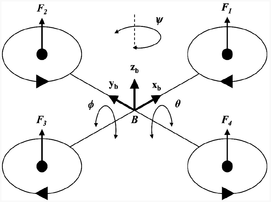
Model of quadrotor UAV.
Supposition
The nose of quadrotor UAV is along the
The angle
Remark 1
During the motion, the state of quadrotor UAV attained by the position angles, that is,
When the quadrotor UAV is on the long flight, the external disturbances, for example, noise, air resistance and so on will disturb the stability of the system. By considering the Newton’s second law and Euler’s dynamic equation, the quadrotor UAV model defined as
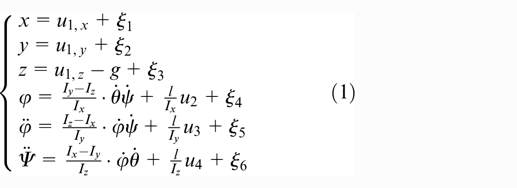
In the above-mentioned equation (1)
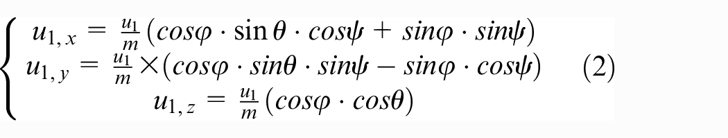
where
Lemma 1
During the flight, the system is disturbed by the external disturbances and thus the interference function
Internal and external control structures
Figure 2 shows the external and internal control structures of the system. Equation (1) shows the mathematical model of position and attitude object of UAV. The input position signal that passes by the sliding mode observer is given as
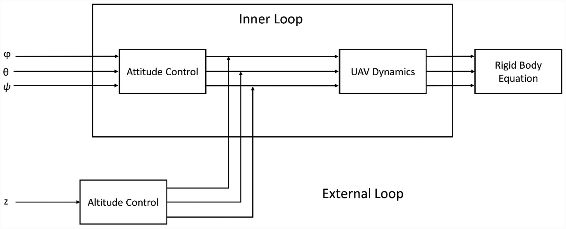
Inner and outer loop structures.
SMC method
The control system of the UAV can track the ideal attitude instruction with the help of sliding mode method. 21 In reference, the derivation and discussion of the sliding mode are discussed as
Here,
The traditional sliding mode controller has a very distinct feature that is to contain a symbolic function. 22 The resulting control instruction will be non-continuous, therefore the sliding surface will produce vibration phenomenon in sliding mode. To avoid chattering phenomenon, sat(s) used to replace the symbol function with the approximate continuous saturation function. The function expression is expressed below
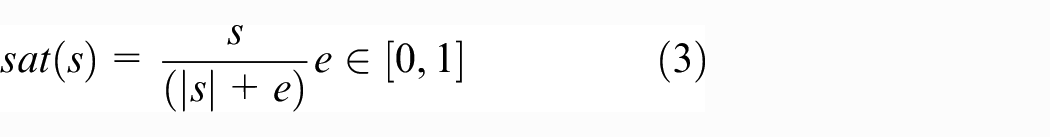
In this research, given
Remark 2
A second-order low-pass filter adopted, and its transfer function is as follows
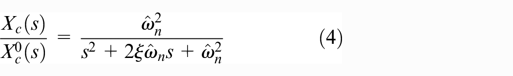
where

The specific structure of the filter design in this research paper, damping ratio
ESO configuration of a quadrotor UAV
The ESO is part of the self-immunity controller discussed in Zhao etal. 23 The core use of ESO is that it can be a good dynamic estimation system (real-time acceleration of the system). The process only needs to use the original object input–output information. ESO can estimate the amount of acceleration in real time. The fundamental reason is that as long as the system satisfies observability conditions, it is possible to extract information from the output. 24
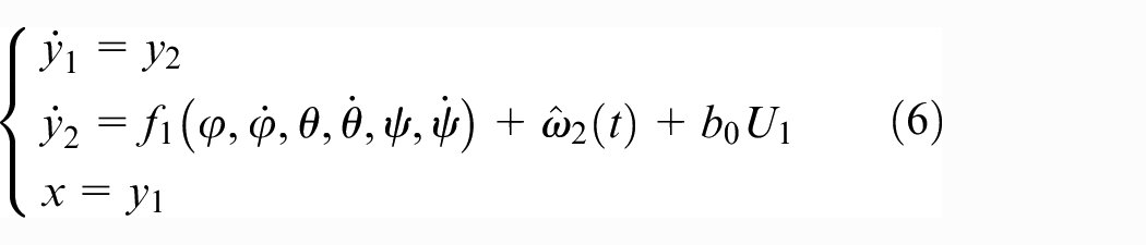
The observed real-time effect is equivalent to the effect of various disturbances (model, un-modeled dynamics and external disturbances). To achieve system linearization this estimation of real-time dynamic compensation is required. The ESO structure is illustrated by an example of the quadrotor roll angle implementation. To combine with the state space equation, the roll angle
Lemma 2
Here,
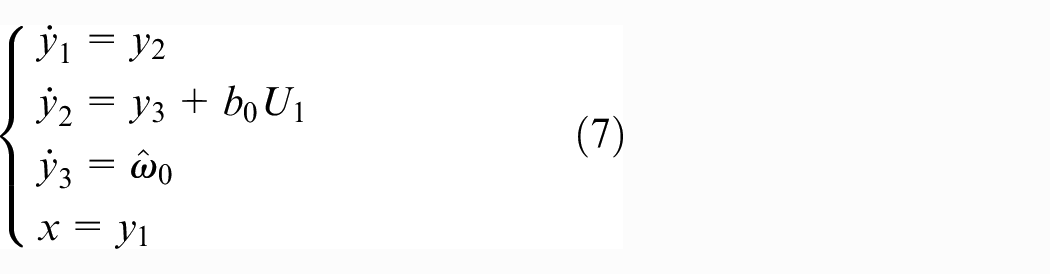
Then, the system to establish the nonlinear expansion state observer is
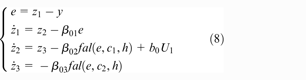
Among them
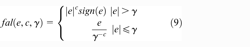
Set the parameters
Architecture improvement in theESO-based sliding mode controller
Sliding mode controller used to achieve the non-linear method of robust control effectively solves the problem of control stability and performance consistency in case of any inaccuracy in the model. Nevertheless, it did not interface with the system to estimate the real-time observation, when the interference is large, the control effect is not ideal.
However, the ESO is for real-time interference estimation and dynamic compensation. The input is the system input and output, output is the sum of estimated state quantity and expanded state quantity (total disturbance), and its structure is easy to combine with other control methods. Thereby increasing the anti-jamming capability of the controller. Therefore, the combination of ESO and sliding mode controller can improve the robustness, anti-interference ability and the attitude control of the quadrotor UAV (Figure 3).
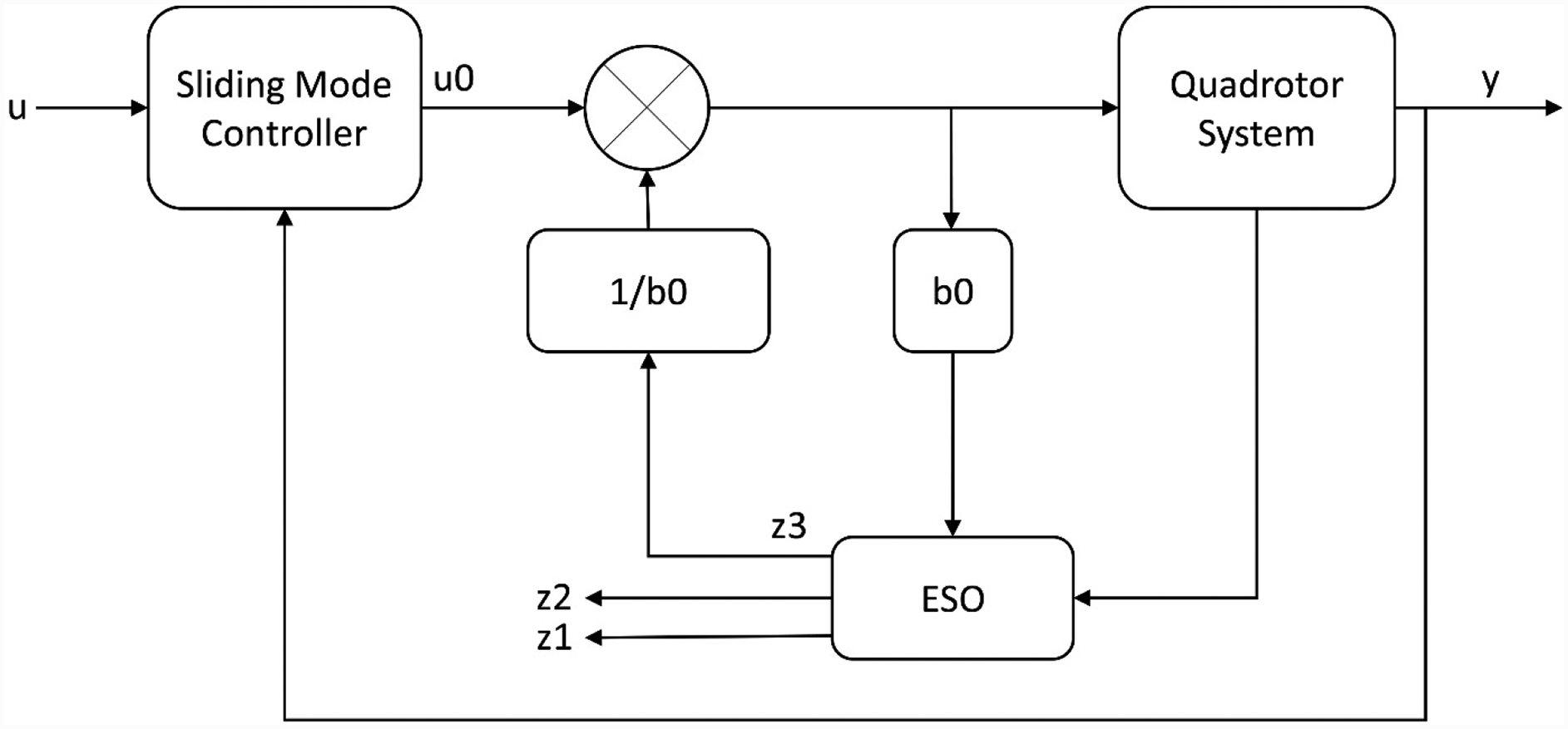
Dual control hierarchy.
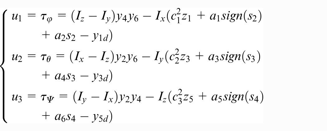
The resulting algorithm based on sliding mode and ESO controller and the inputs rewritten as
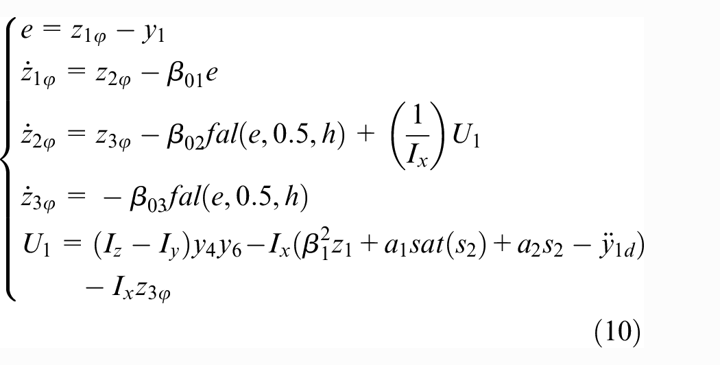
Similarly, to obtain the remaining two attitude angles, that is, pitch and yaw, to control the output
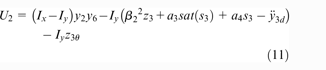
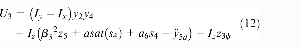
where
Simulation results
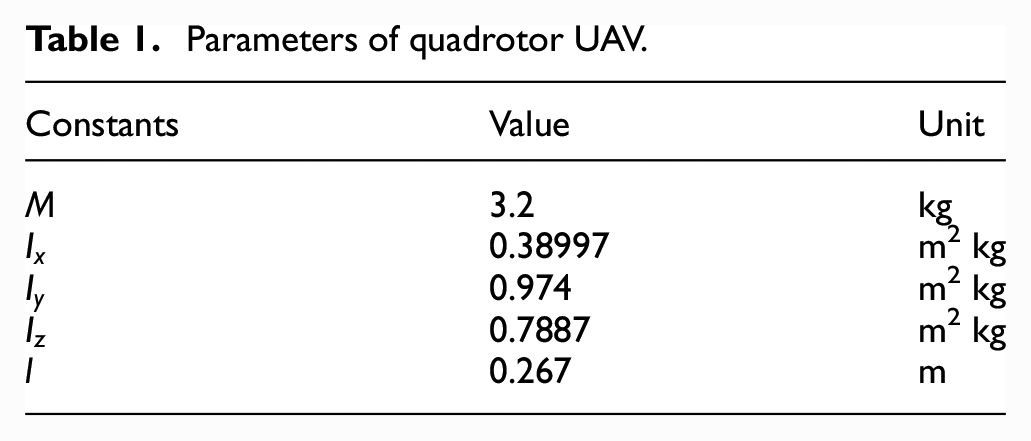
This section determines the efficiency of the proposed method. Table 1 defines the parameters of quadrotor UAV. The overall model of the aircraft is divided into altitude and attitude control sub-models. The arrangement of both the altitude and attitude control loops will make the effective flight as per the referred direction and position as well. The primary errors in the model are controlled and stabilized by the angular subsystem. Moreover, the angular rates converge nearly equal to zero, at the time when the aircraft is at hovering state. The steady state and transient characteristics of the input lie in the range of 0–4 s, along with minimum oscillations. The preferred altitude for hovering scenario is about 2 s. Remaining simulations in Figures 5 to 7 demonstrate the Euler angle responses, angular velocity and the flight trajectory tracking of the quadrotor UAV (Table 2).
Parameters of quadrotor UAV.
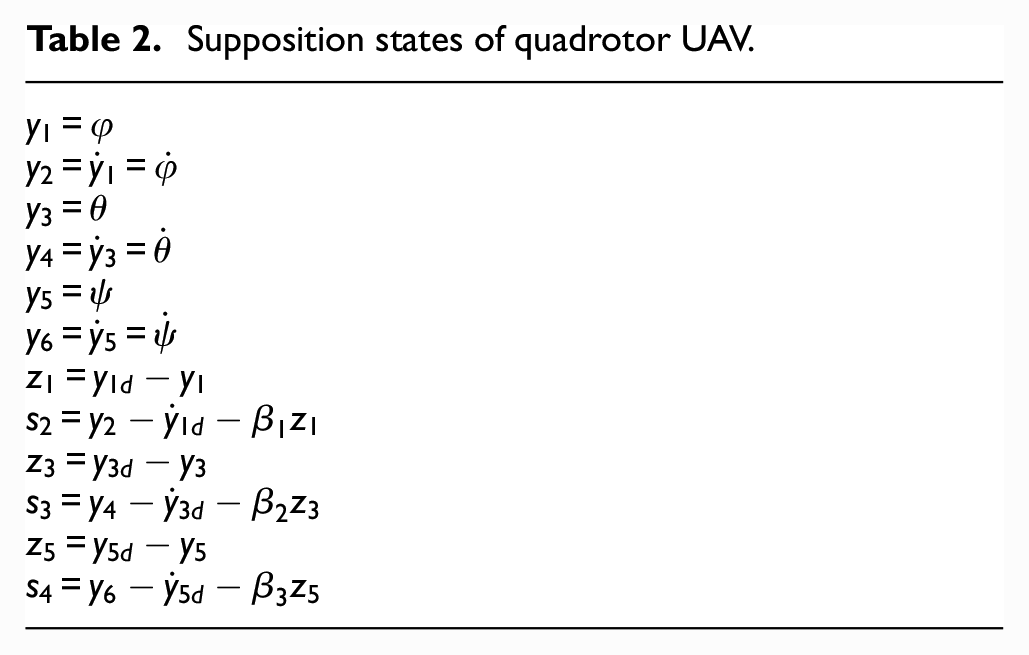
Supposition states of quadrotor UAV.
The sampling time of overall simulation is about 0.212 s for every simulated result that is done for about 50 s. The proposed method that is able to control the maneuvering to the desired path effectively is shown in Figures 4 to 7 correspondingly. The strength of the designed method is demonstrated on MATLAB, Simulink.
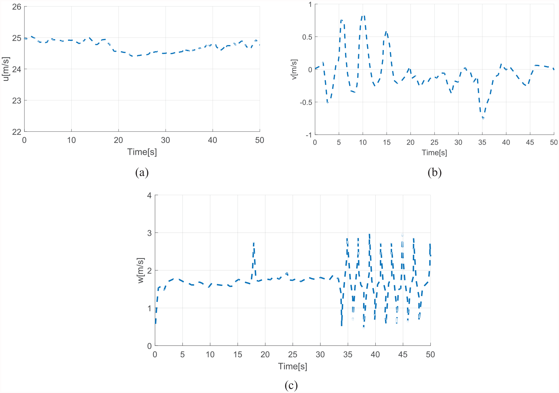
Linear velocity of UAV.
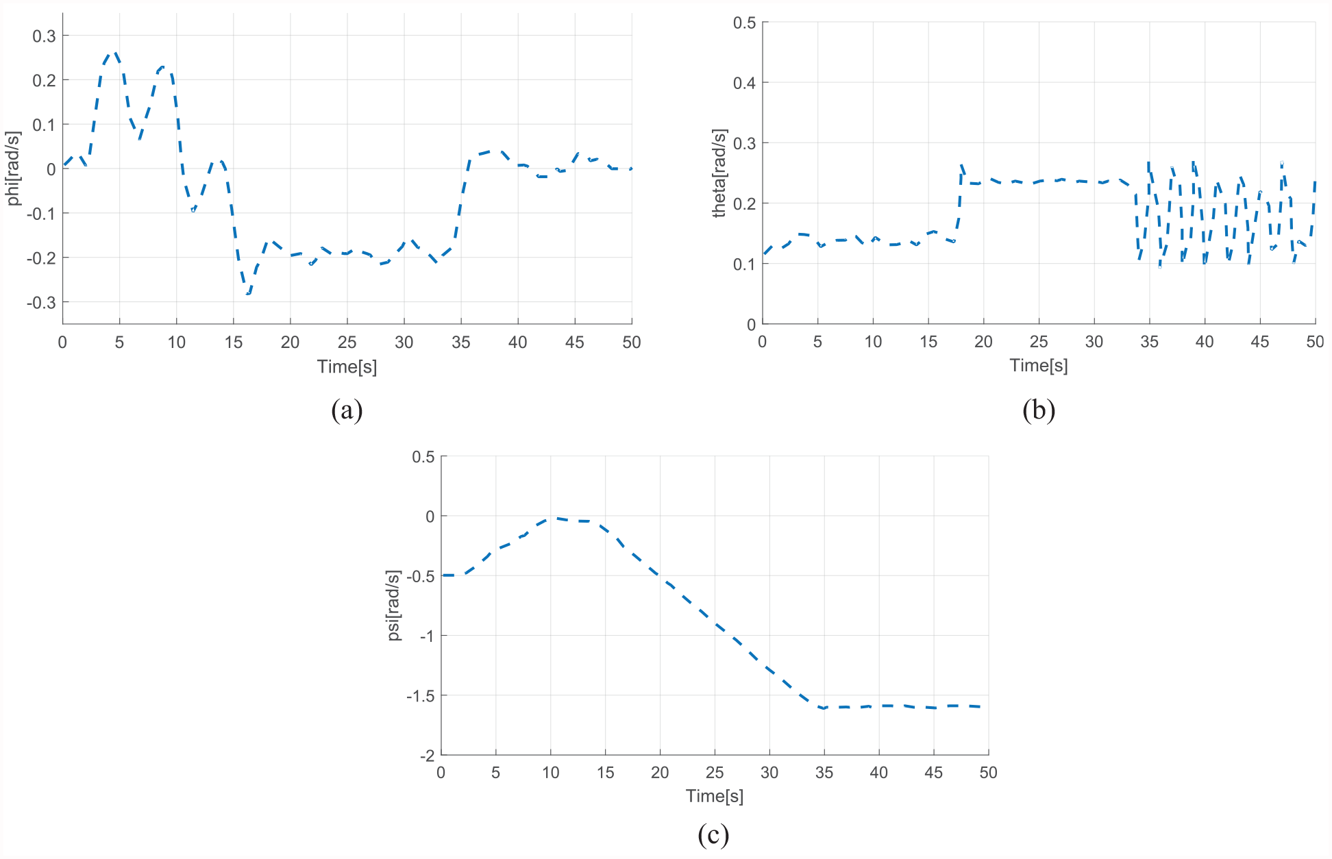
Angular rates of quadrotor UAV.
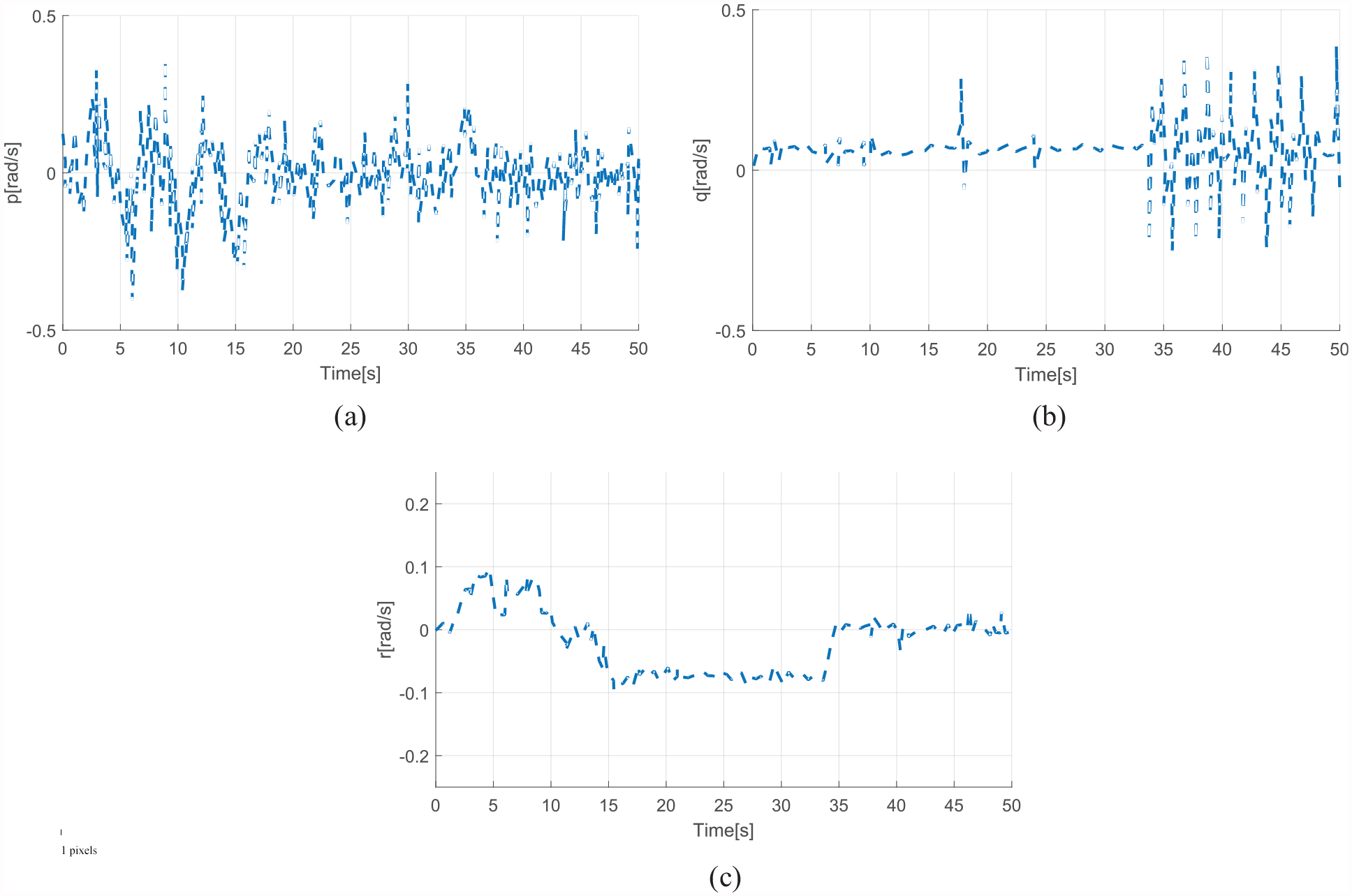
Angular velocity during the flight.
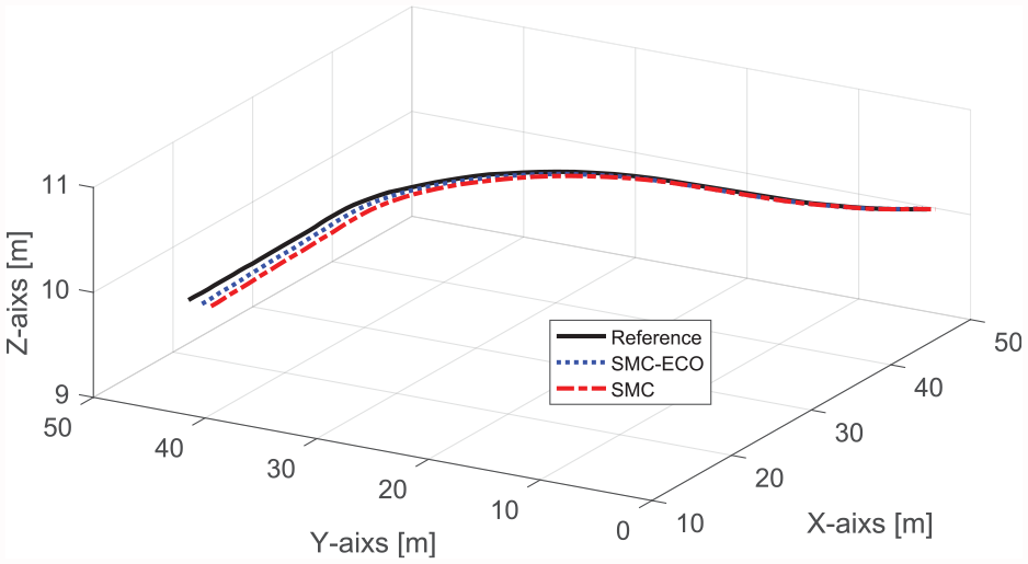
3D diagram of flight trajectory tracking of the UAV.
Figure 4(a) to (c) describes the linear velocity of UAV along with the global (x, y, z) axes. Figure 4(a) represents the x-component of the linear velocity. It starts at around 25 m/s then dips below for a while to finally go back to 25 m/s. Figure 4(b) represents the y-component of the linear velocity. It starts at 0 and then peaks at 0.75 m/s. Then it goes as low as −0.75 m/s before converging back to zero. Figure 4(c) represents the z-component of the linear velocity. It starts at around 0.5 m/s and then remains steady for a while. Then, it keeps oscillating between 0.5 and 3 m/s.
All the above actions goes to zero in finite interval of time after completing the given task. The given task starts from the originated state (takeoff), UAV reaches to desired state and remain in hovering position (lock the altitude) as per given command, and return back to the originated position asymptotically.
The above figure shows the angular rates or Euler angle responses of quadrotor UAV during the whole mission. In Figure 5(a), the angular rate phi starts with zero, go as high as 0.25 rad/s, then starts to decrease and go as low as −0.25 rad/s. Then, after almost 35 s, it converges to zero. In Figure 5(b), the angular rate theta starts with 0.1 rad/s, then reaches its peak at 0.25 rad/s and then oscillates between 0.1 and 0.25 rad/s. In Figure 5(c), the angular rate psi starts at −0.5 rad/s, and then converges to zero before dropping to −1.5 rad/s. In addition, Figure 5(a) to (c) ensures that angular rates track the desired angular rates within an applicable scope.
Figure 6(a) to (c) defines the angular or rotational velocity of UAV along the global coordinate system. Figure 6(a) presents p or roll rate. The roll rate of a UAV is the angular velocity of the rotation of the UAV along x-axis. It starts at zero and then oscillates between −0.3 and 0.3 rad/s. Figure 6(b) presents q or pitch rate. The pitch rate of a UAV is the angular velocity of the rotation of the UAV along y-axis. It starts at zero and remains steady for a while before it starts oscillating between −0.25 and 0.25 rad/s. Figure 6(c) presents r or yaw rate. The yaw rate of a UAV is the angular velocity of the rotation of the UAV along z-axis. It starts at zero and reaches its peak at 0.1 rad/s then drops to −0.1 rad/s. It then converges back to zero. The angular velocity of the rotors of the UAV directly reflects the change in the height of UAV. Decreasing or increasing the angular velocity of the rotors will decrease or increase the altitude of UAV.
Finally, Figure 7 shows the flight trajectory with the reference signal, SMC, and the proposed approach SMC–ESO. It shows that our proposed method has better responses as compared to SMC. It is evident that the SMC–ESO trajectory is closer to the reference signal compared to SMC. In addition, the projected tracking trajectory of the proposed method is able to build the path of quadrotor UAV despite external disturbances and the imprecision of the reference path. It tracks the reference trajectory in an efficient way, as shown in Figure 7. Therefore, it is clear that our proposed method has better robustness with disturbance and noisy surroundings under typical uncertainties.
Conclusion
To summarize the overall paper, it is observed that the proposed flight control method plans the trajectory of the quadrotor UAV in an effective and robust way. In addition, the outer loop (altitude control) and the inner loop (attitude control and UAV dynamics) were modeled to attain the preferred altitude and keep the UAV in hovering mode using SMC. To demonstrate the proficiency of the proposed method, this paper ran simulations on MATLAB, Simulink. The simulation results prove that the trajectory tracking of the proposed method is closer to the reference signal than the classic approach. Finally, the proposed model of quadrotor UAV completes the task despite external disturbances and noise.
Footnotes
Declaration of conflicting interests
The author declared no potential conflicts of interest with respect to the research, authorship, and/or publication of this article.
Funding
The author disclosed receipt of the following financial support for the research, authorship, and/or publication of this article: Shaanxi Provincial Association for Science and Technology Young Talents Lifting Plan Project (20190114) and Special scientific research program of Shaanxi Provincial Education Department (19JK0432).