
Abstract
Here, we report the development of an electrochemical detection method for endotoxin based on the Limulus amebocyte lysate (LAL) assay. A mixture of LAL reagent and endotoxin sample solution was incubated for 1 h. The endotoxin activated a cascade reaction of zymogens contained in the LAL to generate p-nitroaniline (pNA) which was then electrochemically detected by differential pulse voltammetry (DPV). The generated pNA gave a clear peak at –0.75 V vs. silver/silver chloride (Ag/AgCl), which increased with the concentration of endotoxin in the LAL assay solution. This DPV detection was performed using an electrode chip device fabricated from a diamond-like carbon-coated glass substrate. This chip device could detect as low as 10 endotoxin units l−1 at room temperature within 1 h. This novel electrochemical method for the detection of endotoxin appears promising for the development of compact, low-cost and easy-to-use sensors for on-site monitoring of potentially contaminated medical supplies, including dialysis fluid, transplanted tissue and culture medium for assisted reproduction.
Introduction
The Limulus amebocyte lysate (LAL) assay is the most widely used method for the detection of endotoxins. 1 There are three major conventional techniques used in the LAL assay: the gel-clot, kinetic-turbidimetric and chromogenic techniques. Although these techniques are highly sensitive, they are expensive for frequent use, costing approximately $10 per test, and require skilled technicians to perform the analyses. Therefore, it is a significant challenge for most clinics without medical technologists to screen for endotoxin contamination of medical supplies (e.g. dialysis fluid). Endosafe®-PTS™, an easy-to-use assay device supplied by Charles River Laboratories International Inc. (Wilmington, MA, USA), includes a handheld spectrophotometer for chromogenic assay and disposable LAL cartridges pre-filled with all of the reagents needed for the assay. 2 The Endosafe®-PTS™ device makes the on-site monitoring of endotoxin contamination possible without the need for a trained technologist; however, it is still too costly for most clinics to introduce.
As an alternative to photometry, stress-responsive magnetoelastic sensor has been proposed as a low-cost, rapid and highly sensitive method to detect LAL reaction. 3 The use of electrochemical detection is also a promising way of providing low-cost, compact, easy-to-use and highly sensitive assay devices. In electrochemical techniques, the concentration of analyte in a solution is determined by detecting the kinetics of electron transfer between the molecules and the electrode. Electrochemical detection methods have been used extensively as biosensors. 4 For example, theblood glucose meter is one of the most successful hand-sized sensors used for healthcare. 5 It has a low running cost, is easy to handle and does not require any labor-intensive or potentially error-prone laboratory manipulations. If a similar low-cost and easy-to-use endotoxin sensor could be produced, then an appropriate endotoxin monitoring regime could be introduced to facilitate safe medical treatment, particularly in the fields of dialysis, transplantation and assisted reproduction.
Several groups have developed electrochemical endotoxin assay techniques using various methods. The major method uses molecules with endotoxin-binding activities. The binding of the endotoxin to these molecules is detected by impedancemetry,6.7 amperometry with enzyme labeling, 8 or other methods. 9 However, these binding type assays have not reached the sensitivity levels that are required for practical use. For example, the detection limit for the impedancemetry-based method is only 1000 EU l− 1. 7 In contrast, amperometry with enzyme labeling can detect endotoxin concentrations as low as 70 EU l−1 after 60-min incubation 8 , but this still does not meet the required levels for practical use. The upper limit of endotoxin allowed in an ultrapure dialysate has been set at 30 EU l−1 by the Association for the Advancement of Medical Instrumentation (AAMI). 10 This concentration level is the same as the detection limit of the commonly used LAL assay. 11
A second type of electrochemical detection method is the cell-based assay. In this assay, exposure to endotoxin causes release of NO 12 or reporter protein 13 from living cells, which is then detected electrochemically to evaluate endotoxin concentration. These cell-based methods require a long treatment time (24 h) and are difficult to implement owing to the requirement for packaging of live cells.
Previously, we developed a third type of electrochemical endotoxin detection method based on the Limulus factor C (FC) reaction, 14 which is the first component in the LAL cascade reaction. When activated by endotoxin, FC hydrolyzes the synthetic substrate Boc-Val-Pro-Arg-p-nitroanilide to generate an electrochemically active compound, p-nitroaniline (pNA). The liberated pNA is then detected by differential pulse voltammetry (DPV). Electrochemical detection using this FC reaction gives detection limits of 5000 EU l−1 and 1,000 EU l−1 for reaction times of 1 h and 3 h, respectively. However, these detection limits are still not sufficient for practical use.
In the present study, we have developed an electrochemical detection method for endotoxin based on the LAL assay (Figure 1). In the traditional chromogenic technique of the LAL assay, pNA released from the synthetic substrate Boc-Leu-Gly-Arg-pNA (LGR-pNA) by the LAL cascade reaction is detected by using a spectrometer to measure the development of yellow color. In contrast, our method detects pNA using electrochemical signals measured by DPV. We found that the signal increased with very low concentrations of endotoxin because of signal amplification by the LAL cascade reaction. The signal was amplified over 1000-fold compared to that obtained in our previous study using only the FC reaction. Furthermore, this method of detecting endotoxin was successfully conducted using an electrode chip device (Figure 2) to facilitate future development of a handheld-type sensor with practical sensitivity.
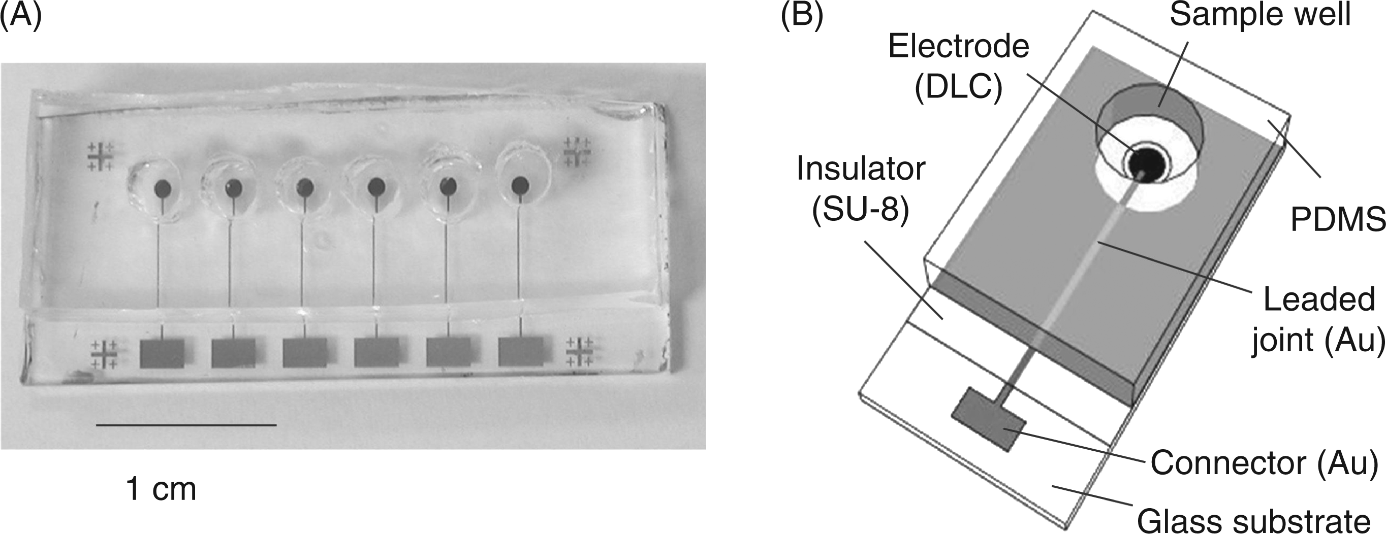
Principle behind the Limulus amebocyte lysate (LAL)-based electrochemical endotoxin assay. (A) Photograph of the electrode chip device; (B) structure of the device. PDMS, poly-dimethyl siloxane.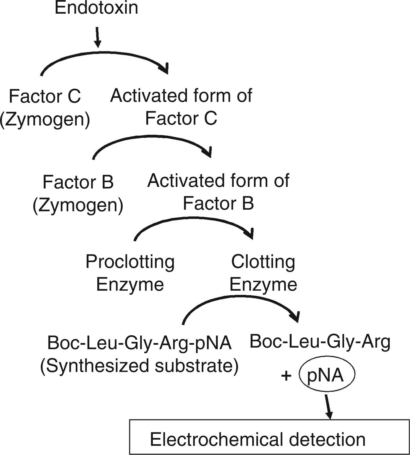
Materials and methods
Materials and reagents
The Endospecy® ES-24S set was gifted by Seikagaku Biobusiness Corp. (Tokyo, Japan). This set contains assay buffer and reagents (freeze-dried LAL reagents and LGR-pNA) divided into single-test vials. Escherichia coli O55:B5 control standard endotoxin (Lonza, Portsmouth, NH, USA) was diluted with endotoxin-free water (Lonza) to obtain standard endotoxin solutions. Just before use, the standard solutions were mixed by vortexing vigorously for more than 15 min. LGR-pNA (Bachem, Bubendorf, Switzerland) and pNA (Wako Pure Chemical Industries, Osaka, Japan) were dissolved DMSO to obtain 10 m
Fabrication of the electrode chip device
The electrode chip device consisted of an electrode chip and wells made of poly-dimethyl siloxane (PDMS; SILPOT W/C, Dow Corning Toray, Tokyo, Japan). Figure 2 shows the fabricated device (Figure 2A) and its structure (Figure 2B). An electrode chip with six carbon electrodes was constructed using photolithography. A glass substrate coated with a conductive diamond-like carbon film (a generous gift from Nanotec Corp., Chiba, Japan) was cut into 1.5 × 3.5 cm pieces. The resistivity and thickness of the diamond-like carbon film were 2.2–3.0 × 10⁻⁵ Ω·cm and 150 nm, respectively. Six circular carbon electrode patterns, each 1 mm in diameter, were made by etching with O2 plasma asher (LTA-101; Yanako Co., Tokyo, Japan) through the silicon-based positive photoresist (FH-SP; Fuji-Hunt Electronics Technology, Tokyo, Japan) pattern. The FH-SP was spin-coated at 5000 rpm for 30 s and pre-baked at 90°C for 90 s. After exposing it to a mercury lamp through the photo-mask for 30 s, the FH-SP was developed with tetramethylammonium hydroxide (TMAH)-containing developer (FHD-5; Fuji Film Electronics, Tokyo, Japan). The excess region of the diamond-like carbon film was removed by O2 plasma asher at 100 W for 60 min. The binder metal was etched by incubating in a 30% hydrogen peroxide solution for 60 min. Gold leaded joints and connectors were fabricated by conventional photolithography, as described previously. 15 Briefly, a gold film (200 nm thickness) with a titanium and palladium adhesive layer was sputter-deposited in a sputtering machine(L-332S-FH; Anelva Corp., Tokoyo, Japan) on the pattern of a positive photoresist (S1818; Shipley Corp., Marlborough, MA, USA). After removal of the photoresist with acetone (lift-off), an insulation layer (∼5 μ m thickness) was fabricated using a negative photoresist (SU-8 3005; MicroChem Corp., Newton, MA, USA) to expose the electrode area to the solution. The wells (diameter, 3 mm; depth, 5 mm) for sample solutions were formed by casting PDMS prepolymer against an acrylic master plate, curing at room temperature (22–26°C) for 24 h, and then peeling from the master. The flat bottom of the PDMS well was pressed on the SU-8 insulator surface ofthe electrode chip to ensure tight bonding.
Optimization of O2 plasma ashing time for endotoxin removal
In order to optimize our procedure, we examined the appropriate O2 plasma ashing time to remove the endotoxin contaminating the chip device. 16 A 300-μl solution of 5000 EU l−1 endotoxin was added to the PDMS well (the same as used on the electrode chip device) on the glass substrate (Micro slide glass S-1215; Matsunami Glass, Osaka, Japan) and incubated at room temperature for 2h in order to adsorb the endotoxin onto the glass substrate. After washing gently with distilled water, the PDMS well was removed. The glass substrate was then treated with O2 plasma at 100 W for 0–90 s. The oxygen pressure in the chamber was set at 50 Pa. The remaining endotoxin was detected by a chromogenic technique as follows: 200 μl assay buffer containing the LAL reagents (prepared according to the Endospecy® ES-24S set protocol) was added to the new PDMS well (diameter, 8 mm; height, 12 mm) placed on the glass substrate. After 1 h incubation at room temperature, the solution was transferred to a 96-well plate and the absorbance at 405 nm was measured using a plate reader (Model 680; Bio-Rad, Hercules, CA, USA).
Equipment and methods for electrochemical measurements
Electrochemical measurements were carried out using apotentiostat (CompactStat; Ivium Technologies, Eindhoven, the Netherlands). A glassy carbon disc electrode (BAS Inc., Tokyo, Japan; diameter = 1.0 mm) was employed as a probe-type working electrode. A platinum wire was used as a counter electrode. DPV was carried out with a pulse time of 70 ms, a pulse amplitude of 50 mV, a potential step of 5 mV and a scan rate of 5 mV s−1. Cyclic voltammetry (CV) was performed in order to characterize the basic performance of the electrode chip device. The potential of the working electrode of the chip was scanned at 100 mV s−1 between –0.6 V to + 1.0 V in 4 m
Electrochemical endotoxin assay method
Following the protocol in the Endospecy® ES-24S set, 200 μl of assay buffer was added to each test vial in order to make the reagent solution. For the assay using the probe-type electrode, 100 μl of the reagent solution was transferred to a 96-well plate, and then 100 μl of endotoxin solution was added. After incubating at room temperature for 1–2 h, the glassy carbon working electrode, the reference electrode and the counter electrode were inserted together into the well for electrochemical detection. For the assay using the electrode chip device, the device was first treated by O2 plasma at 100 W for 30s in order to remove any endotoxin contamination on the device. Next, 20 μl of the reagent solution was transferred into each well on the chip and 20 μl of endotoxin solution was then added to each well. The chip was incubated at room temperature for 1 h. Following the incubation period, the reference electrode and the counter electrode were inserted together into the well for electrochemical detection. All procedures preceding the electrochemical detection were performed in a laminar flow cabinet in order to eliminate the possibility of endotoxin contamination.
Results and discussion
Basic characterization of the electrochemical behavior of LGR-pNA and pNA
We first characterized the basic electrochemical behavior of LGR-pNA and pNA. Figure 3 shows the differential pulse voltammograms of the mixture of pNA and LGR-pNA in the assay buffer of the Endospecy® ES-24S set. The total concentration of pNA and LGR-pNA was set at 100 μ Differential pulse voltammograms for mixtures of Boc-Leu-Gly-Arg- p-nitroaniline (LGR-pNA) and pNA in assay buffer. The total concentration of LGR-pNA and pNA was 100 μ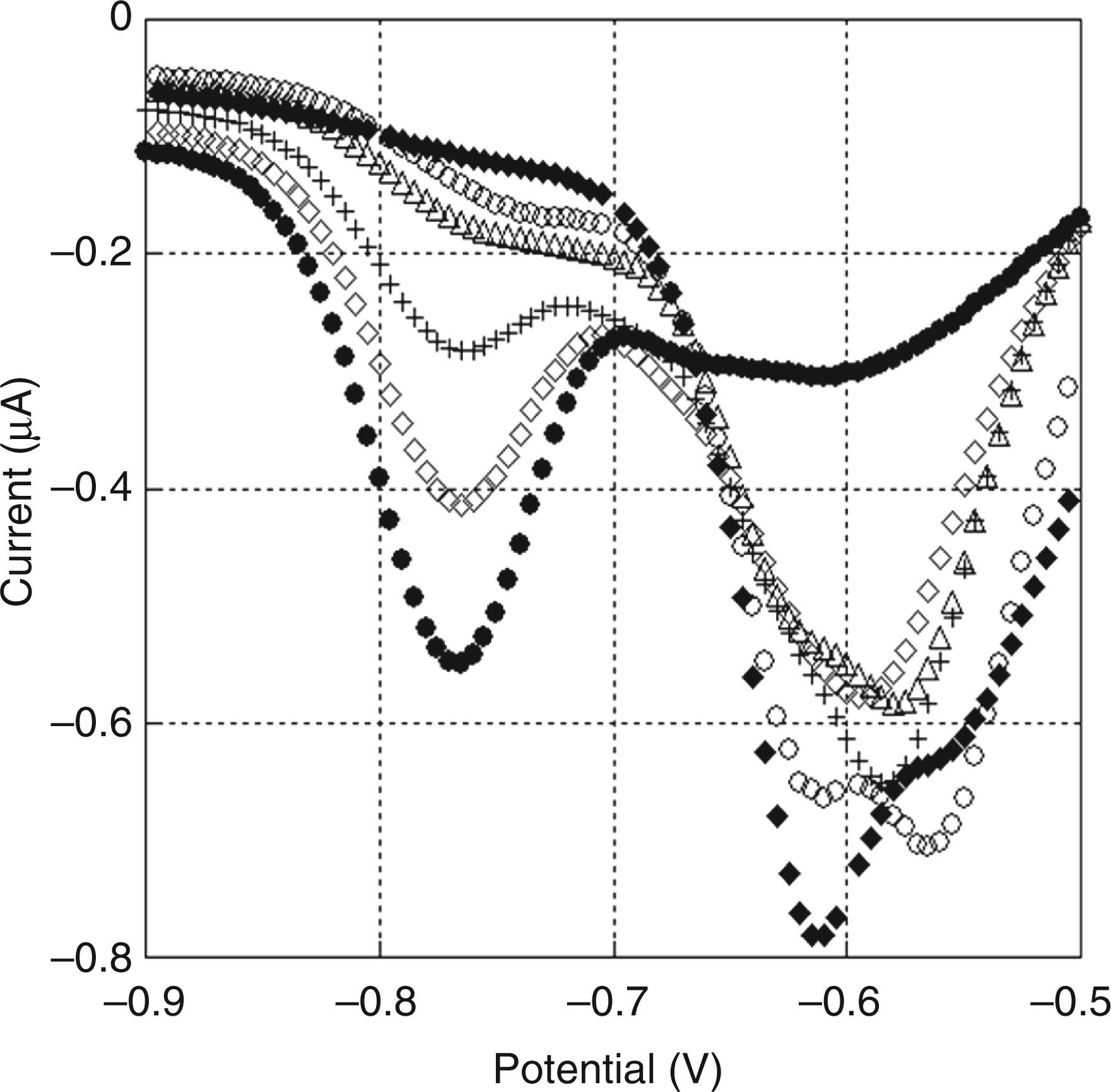
Endotoxin assay using a probe-type electrode
Next, we performed an electrochemical endotoxin LAL assay using a probe-type electrode. A mixture of 100 μl assay buffer containing the LAL reagents and 100 μl endotoxin sample solution was incubated at room temperature for 1 h or 2 h in a 96-well plate. The electrodes were then inserted into the well to perform the DPV measurements. Figure 4(A) shows typical voltammograms ranging from –0.85 V to –0.65 V. The reduction peak at –0.75 V increased with the endotoxin concentration. As mentioned earlier, this peak originates from the reduction of pNA, which is the product of the hydrolysis of LGR-pNA. The difference between the current at –0.75 V for the sample solution and that for the negative control solution (in the absence of endotoxin) was used as the electrochemical signal for detection. Figure 4(B) shows the calibration plot of these signals versus the endotoxin concentration. The DPV responses depend on the incubation time and increase with the endotoxin concentration. Each point on the calibration plot corresponds to a mean value and the error bars indicate the standard deviation obtained from three independent measurements. The detection limits were found to be 10 EU l−1 and 0.1 EU l−1 for reaction times of 1 h and 2 h, respectively. Compared with our previous method using only the FC reaction, the present method shows that more than 1000 times signal amplification could be achieved with the LAL cascade reaction. Importantly, the detection limits of this novel method cover the concentration ranges required for practical use.
(A) Typical differential pulse voltammograms obtained with a probe-type electrode for the standard endotoxin solutions incubated with the Limulus amebocyte lysate (LAL) reagent solution in a 96-well plate for 1 h. The concentration of endotoxin is indicated as follows: (×) 0; (○) 1; (△) 10; (•) 100; (▴) 1000 EU l−1. (B) Calibration curves for the quantitative detection of endotoxin using the LAL-based electrochemical assay with the probe-type glassy carbon electrode. Incubation times were 1 h (×) and 2 h (♦). Error bars represent standard deviations (n = 3).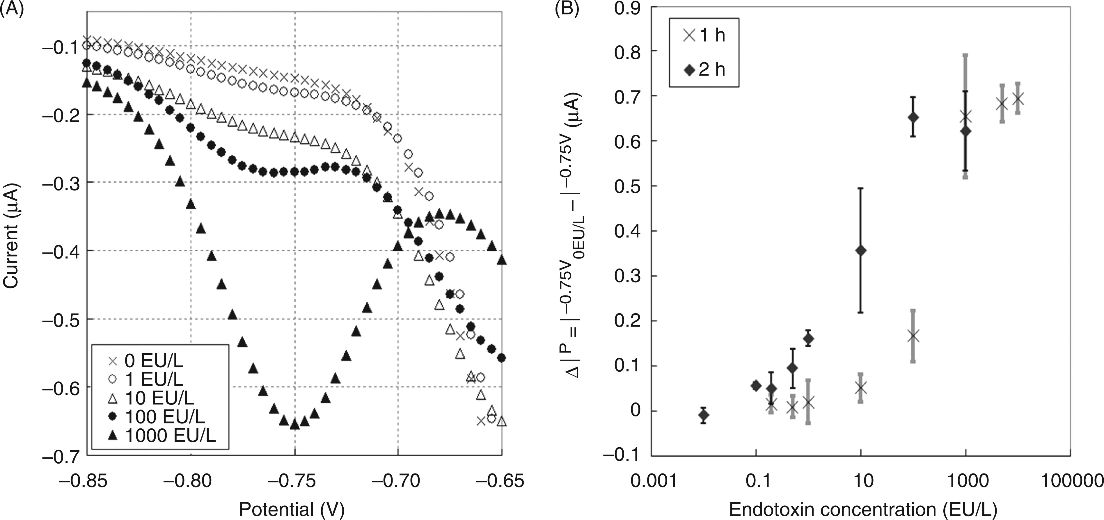
Characterization of the electrode chip device
We then attempted to detect endotoxin on a more compact device closer to the size of a handheld-type sensor. First, we fabricated the electrode chip device and characterized its electrochemical performance. Figure 5 shows the cyclic voltammograms obtained for 4 m Cyclic voltammograms for a 4 m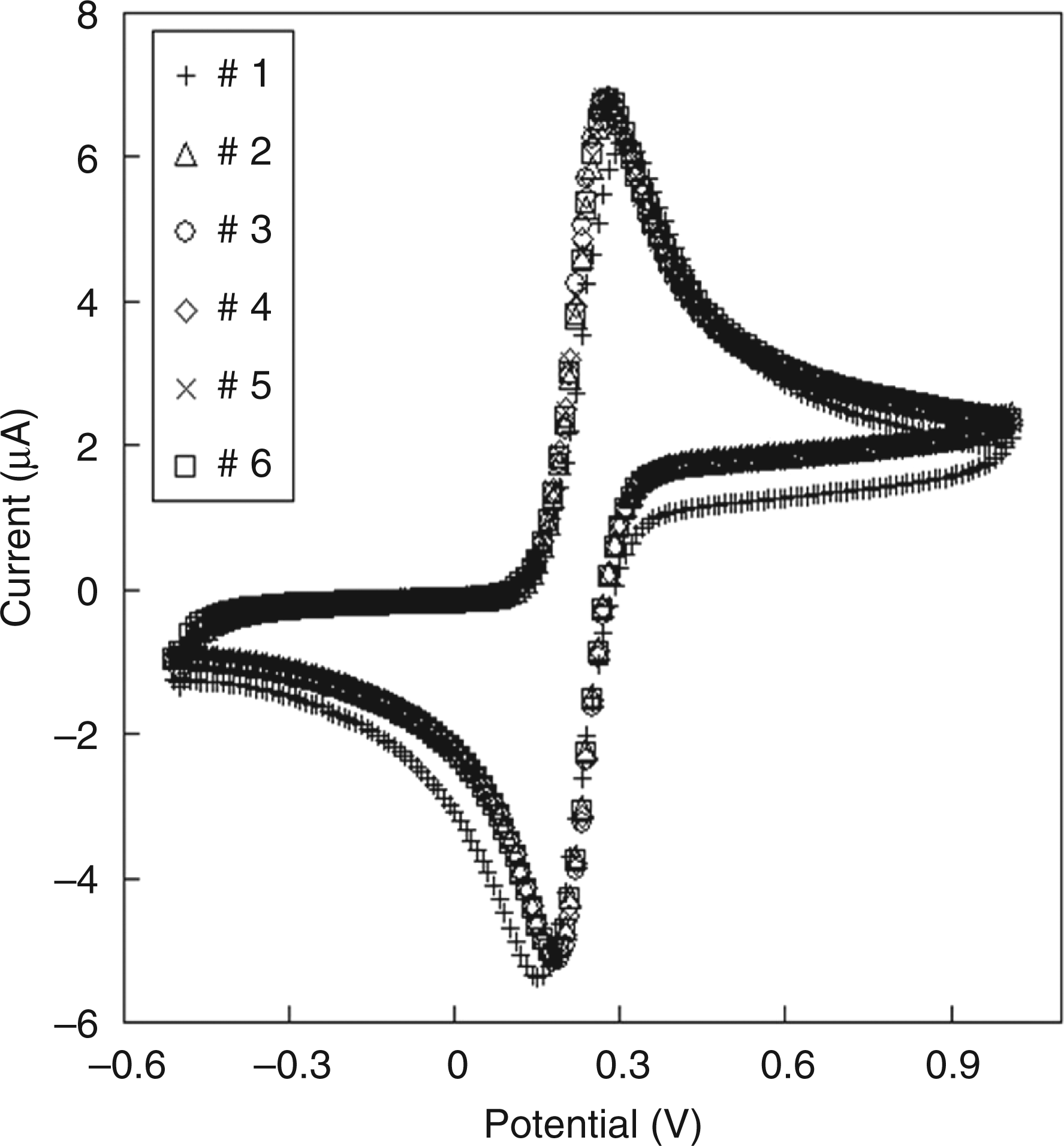
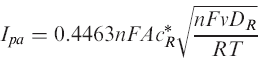
We calculated the electrode areas from the oxidation peak currents on the cyclic voltammograms (Figure 5) using the following equation 19
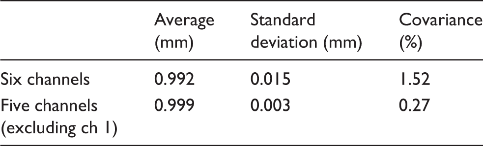
Statistical values of calculated electrode diameters
Optimization of O2 plasma ashing time for endotoxin removal
O2 plasma ashing is also effective in removing endotoxin contaminating the chip device. Figure 6 shows the results of the chromogenic assay for detection of endotoxin remaining on the glass substrate after plasma ashing. Washing the endotoxin-contaminated areas with distilled water removed most of the endotoxin, but 0.1–8.0 mEU endotoxin still remained on the glass (ashing = 0 s; n = 5). After O2 plasma ashing for 10 s, the remaining endotoxins were 0.1–5.1 mEU (n = 3). When the glass substrates were treated for over 30 s, the endotoxin concentration decreased to less than 0.5 mEU. On the basis of these results, we employed a 30-s O2 plasma treatment to remove endotoxin contaminating the electrode chip device.
Endotoxin remaining on the glass substrate after O2 plasma ashing was evaluated with the chromogenic technique using the Endospecy® ES-24S set.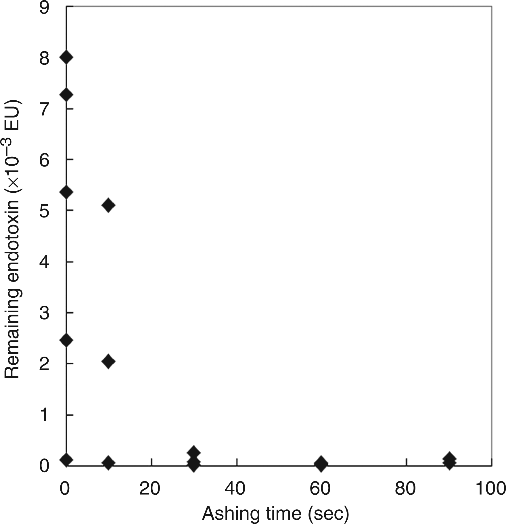
Endotoxin assay using the electrode chip device
Lastly, we performed an electrochemical endotoxin assay using the electrode chip device. To do this, 20 μl of the reagent solution and 20 μl of endotoxin solution were added to each well on the device and incubated at room temperature for 1 h. The reference electrode and counter electrode were then inserted into the well to perform the DPV measurements. Figure 7(A) shows typical voltammograms between –0.70 V and –0.95 V. Peaks indicating the reduction of liberated pNA were observed between –0.80 V and –0.85 V. The difference between the peak current and the average current for the control solution (in the absence of endotoxin; n = 3) atthe same potential was used as the electrochemical signal for detection. Figure 7(B) shows the calibration plot of these signals versus different endotoxin concentrations. Each point on the calibration plot corresponds to a mean value, and the error bars indicate the standard deviations obtained from three independent measurements. Similar to the measurements obtained using a probe-type electrode, we noted that the signal increased with the concentration of endotoxin in the range of 10–1000 EU l−1, which covers the concentration levels required for sufficient clinical monitoring of endotoxin contamination. The successful detection of 10 EU l−1 endotoxin within 1 h using the small electrode chip indicates the potential usefulness of this method in the futuredevelopment of portable and highly sensitive endotoxin sensors. We are presently in the process of developing a lower cost electrode chip, which is required for practical use of the sensor.
(A) Typical differential pulse voltammograms obtained with the electrode chip device for the standard endotoxin solutions incubated with the Limulus amebocyte lysate (LAL) reagent solution for 1 h. The concentration of endotoxin is indicated as follows: (×) 0; (○) 1; (△) 10; (•) 100; (▴) 1000 EU l−1. (B) Calibration curve for the quantitative detection of endotoxin using the chip device for 1 h incubation time. Error bars represent standard deviations (n = 3).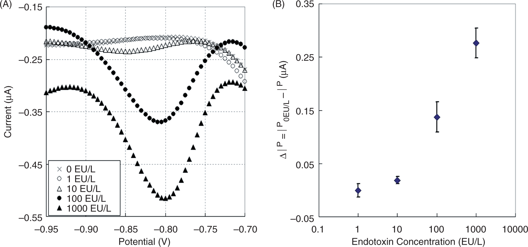
Conclusions
In this study, we demonstrated a novel electrochemical method for the detection of endotoxin based on the LAL assay. The electrochemical behavior of LGR-pNA and pNA was characterized and the DPV measurements with a probe-type electrode indicated that pNA can be specifically detected in the presence of LGR-pNA. The DPV signal for pNA in the LAL assay solution with LGR-pNA increased with the concentration of endotoxin in the solution. The detection limits were found to be 10 EU l−1 and 0.1 EU l−1 for the LAL reaction times of 1 h and 2 h, respectively. We fabricated an electrode chip device containing six disk electrodes of diamond-like carbon (each 1 mm diameter). Endotoxin contamination on the device was successfully removed by O2 plasma ashing for 30 s. Assays using this chip device effectivelydetected endotoxin in the concentration range of 10–1000 EU l−1 within 1 h. We conclude that this method provides an on-site, rapid, easy-to-use, and portable detection system for endotoxins in the clinic.
Footnotes
Acknowledgements
This work was partly supported by a Grant-in-Aid for Scientific Research (A) (No. 22245001) from the Japan Society for the Promotion of Science (JSPS) and by Special Coordination Funds for Promoting Science and Technology, Formation of Innovation Center for Fusion of Advanced Technologies from the Japan Science and Technology Agency.