
Abstract
Inertial measurement units (IMUs) offer a promising tool for assessing and monitoring performance in acrobatic gymnastics, potentially providing coaches with valuable biomechanical insights. IMU and motion capture data were collected synchronously in laboratory conditions while acrobatic gymnasts performed two acrobatic skills: a back tucked somersault (BTS) and a back straight somersault (BSS). Resultant linear acceleration and angular velocity (mediolateral axis) were calculated using data from an optical motion capture system (MOCAP) and using an IMU placed in the sacrum of 19 national and international level acrobatic gymnasts, divided into 11 pairs. The entire signals were compared using statistical parametric mapping. Results showed that the IMU systematically underestimated both acceleration and angular velocity when compared to the reference system. For the base gymnast's acceleration, four (BTS) and six (BSS) clusters showed significant differences. For the top gymnast, both tasks differed approximately 100% of the time (p < .001). Regarding angular velocity, eight (BTS) and three (BSS) clusters showed significant differences, reinforcing the underestimation observed. Our findings suggest that IMU data is not sensitive to the kinematic phases (speeds, accelerations, decelerations) occurring during the top gymnast flight. These findings suggest that a single IMU may not provide reliable or sufficient information for performance assessment in acrobatic gymnastics training.
Introduction
The main challenge for motion analysis in sports is coordinating internal and external validity to obtain reliable data that can be generalized to real-world settings. A potential solution would be to integrate motion capture (MOCAP) systems directly into training or competitive environments. However, the use of MOCAP systems in these settings remains limited due to their lack of portability and low ecological validity. Inertial measurement units (IMU) have emerged as a promising alternative to overcome the limitations of an optical 3D MOCAP. 1 But could an IMU sensor provide valid and useful information to coaches about acrobatic gymnasts’ performance?
Examples of IMU applications in gymnastics or pair tasks are reported in: (1) artistic gymnastics: to measure upper and lower limb loading in competitive level gymnasts 2 ; (2) horse riding: to analyze the kinematics and the interactions of the rider and horse, 3 and (3) acrobatic gymnastics: to measure the kinematics of experienced and novice top gymnasts during a backward tucked somersault. 1 This last analysis focused on the top gymnasts’ aerial motion, without addressing data quality. Overall, IMU has been able to detect changes of movement direction and heading angles with acceptable validity, but IMU data or derived kinetic or kinematic variables may have inconsistency and over-estimation; thus, larger sample sizes and agreement on the metrics used and sensor placement were suggested to improve results. 4
Studies have reported the use of a single IMU placed in the sacrum to accurately represent the center of mass (CoM) in multiple tasks and sports. In ski skating, the use of both accelerometers and gyroscopes in the IMU enhances the precision of the measurements, achieving errors as low as 8 mm in all directions of CoM displacement. 5 During walking, the IMU predicted lower limb kinetics and kinematics with fair accuracy compared to an optical MOCAP, indicating its potential for dynamic data estimation.6,7 The IMU estimated sagittal plane components and magnitude of step-average ground reaction force during a standing sprint start, as well as the vertical component and magnitude of step-average ground reaction force during a change of direction task. 8 In swimming, the same method provided relevant kinematic variables to different swimming phases, aiding in performance assessment across various techniques. 9 However, a congress paper showed that this system tends to over/underestimate the CoM position depending on the task performed: static vs dynamic. 10 The underestimated or overestimated parameters indicate the need for robust validation procedures before relying solely on IMU data in biomechanical research or practical applications.
These considerations are particularly relevant in acrobatic gymnastics, where partner-assisted flight involves a throwing motion. The base gymnast throws the top gymnast, as the top performs a modified Countermovement Jump (CMJ). Overhead throwing is an eloquent full-body motion that requires tremendous coordination from the time of force generation to follow-through. 11 Since the top gymnast is not a rigid load, the motion and coordination between both gymnasts is crucial for the performance of the aerial phase, 12 which includes the performance of somersaults and/or twists. The introduction of an IMU into the training environment could provide fast data-driven feedback that would help coaches refine athletes’ techniques in almost real time. However, for IMUs to be practical for training sessions, the setup process - including sensor placement, calibration and, most challenging and critical, data processing - must be very straightforward, without disrupting the training flow or discouraging regular use. Therefore, this study aims to compare the linear acceleration and angular velocity provided by a single IMU placed in the sacrum with those of the CoM extracted from a conventional optical MOCAP system. According to the literature, we hypothesized that IMU should have enough validity to provide information for the coach in a training environment. This would be reflected in the similarity of the linear acceleration and angular velocity curves obtained from the IMU and the MOCAP system, assessed using statistical parametric mapping.
Material and methods
Sample characterization
Nineteen acrobatic gymnasts (11 bases and 8 tops) from national and international competition levels (1st division and elite) volunteered for this study. The bases’ group consisted of 8 females (median (interquartile range): 17 (5) years old, 1.64 (0.07) m tall, 62 (14.1) kg of mass, and 8 (5) years of experience) and 3 males (16 (3) years old, 1.72 (0.07) m tall, 67 (14.2) kg of mass and 4 (4) years of experience). The tops’ group included 6 females (12.5 (6) years old, 1.46 (0.08) m tall, 32.8 (3.7) kg of mass, and 6 (1) years of experience) and 2 males (13 (2) years old, 1.43 (0.24) m tall, 39.8 (13.4) kg of mass, and 9.5 (5) years of experience). The gymnasts were organized into 11 pairs, with 9 female and 2 male pairs.
All participants, or their legal guardians, were informed of the study's purpose, procedures, benefits, and risks, and gave their voluntary and informed consent to participate, in accordance with the Declaration of Helsinki and the local research Ethics Committee (CEFADE 02.2022).
Procedures
Gymnasts performed their regular warm up for 15 min. One IMU (Trigno™ Wireless EMG system, Delsys Inc., Boston, MA, USA), operating at 370 Hz with one triaxial accelerometer (capacity of 6G) and a triaxial gyroscope (capacity of ± 2000°/s) was fixed with tape on the sacrum of both base and top gymnasts. The pairs tested the tasks prior to data collection to ensure they felt comfortable with the IMU placement and the testing environment.
Kinematic data was also collected using an optical MOCAP system (8 miqus video cameras, Qualysis AB, Sweden), at a sampling frequency of 85 Hz to ensure a resolution of 1920 × 1080 pixels. The capture volume was calibrated using a wand, with a maximum acceptable error established as 0.8 mm. The base gymnast stood in the middle of the laboratory, with a 2 × 3 m gymnastics mat placed on the floor as a safety measure.
The coordinate systems of the IMU and the optical MOCAP system were aligned prior to data collection. The IMU was placed on the sacrum with its arrow oriented upwards to match the orientation of the global MOCAP coordinate system. The MOCAP and the IMU were synchronized using a trigger from the Delsys synchronization interface (Trigno Wireless System, Delsys Inc., Boston, MA, USA), in accordance with the manufacturer's recommendations (Qualisys). Each pair performed 10 trials of two distinct tasks (Figure 1A and B): the back tucked somersault (BTS) and the back straight somersault (BSS). These tasks differ in difficulty level, according to the official code of points, 13 and are characterized by specific body positions. From a biomechanical perspective, the radius of rotation is greater in the straight body position, resulting in a decrease in angular velocity to maintain a constant angular momentum. Conversely, in the tucked body position, the radius of rotation decreases, leading to a significant increase in angular velocity. The focus of this work is not to compare both tasks, but to understand the sensitivity of both optical MOCAP and IMU systems to capture the kinematic differences between both tasks.
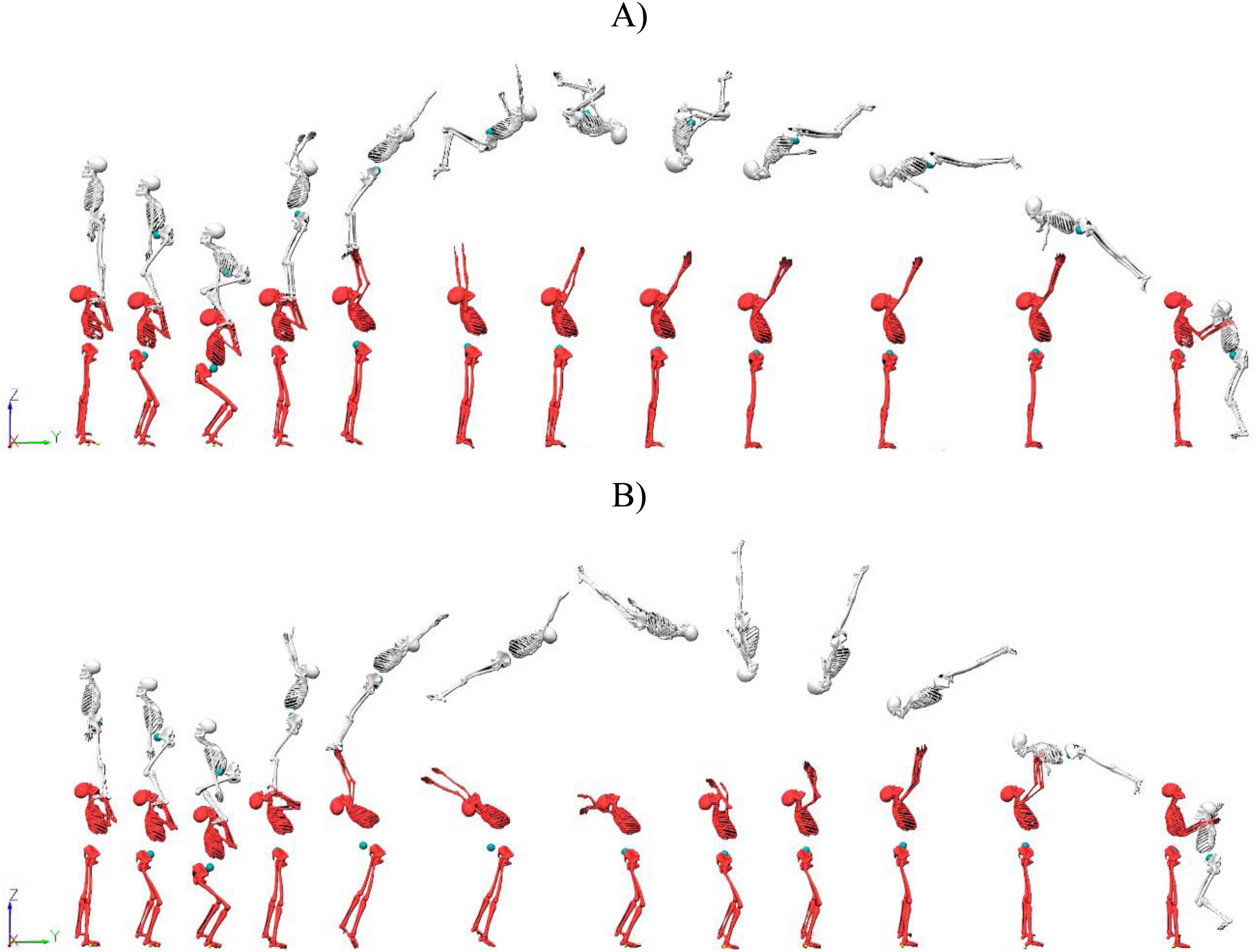
A. Representation of the biomechanical models of the base (red model) and the top gymnast (grey model) performing a back tucked somersault. B. Representation of the same biomechanical models for a back straight somersault.
The onset was defined as the first instant where the CoM velocity presented a downward velocity. The offset was established as the instant where the CoM angular momentum returned to the starting values. Each trial was treated as an independent observation.
Data processing
Kinematic data was processed using a markerless software (Theia Markerless, Inc., Canada) and the 6 degrees of freedom models were exported to Visual3D (HAS-Motion, Canada) for analysis. To capture the rotational motion of the top, the optical MOCAP system data was filtered using a Generalized Cross-Validation Smoothing Spline lowpass filter (10 Hz). For the IMU, an equivalent Butterworth lowpass filter (10 Hz) was applied.
The center of mass linear acceleration (CoM
α
) was calculated via Visual3D, using the derivative of velocity. The center of mass angular velocity (CoM
ω
) was calculated and extracted from a customized routine executed in MATLAB (R2020a, The MathWorks Inc., Natick, MA, USA), with the following steps. First, a saved script in Visual3D was used to calculate the angular momentum (L) for each of the listed segments (right foot + right shin + right thigh + left foot + left shin + left thigh + pelvis), using equation 1. To calculate the CoM
L
, the resulting signals for all segments about the CoM were summed together, as equation 2.

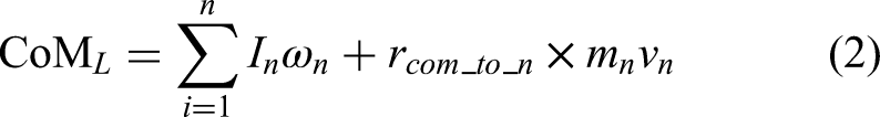
Where CoM
L
is the angular momentum about the model CoM, I is the moment of inertia,
Similarly, the model's I around the model's CoM is the sum of each segment's I around the model's CoM. The equations apply to each segment, and the total body I is the sum of these values, forming a 3 × 3 matrix, in which the data at each frame represents the 9 values in the matrix. A parallel axis theorem term accounts for the distance each segment is from the point where is calculated the CoM position (often this point is the total body CoM). Thus, I about any axis parallel to that axis through the CoM is given by:

Thus, I (relative to global coordinate system) is given by summing two terms:

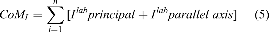
If the I of each segment is resolved about the model's CoM in the laboratory coordinates, the CoM
I
is simply the sum of the segments’ I about the model's CoM, as:
These contents are based on Fred Yeadon's research.14–18
L and I were used to obtain
Finally,
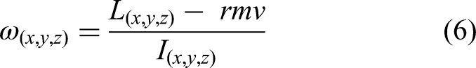
IMU data was extracted using Delsys File Conversion (Delsys Inc., Boston, MA, USA), and the filtered data from linear acceleration (α) and angular velocity (ω) was used for analysis. The data from both methods were time-normalized to 1000 data points. This procedure facilitates waveform analysis over the full movement duration and enables comparison between recording systems with different original sampling frequencies.
The resultant α was estimated for both optical MOCAP and IMU data to account for the movement occurring in all axes:

Accordingly, the variables used for analysis were the resultant α of both gymnasts and the ω of the top gymnast in the rotation axis (mediolateral).
Statistical analysis
The Statistical Parametric Mapping (SPM) with paired sample T-tests was used to compare the time series from the conventional method (optical MOCAP) and the IMU, in MATLAB, using the open-source code SPM1d (v.M0.1, www.spm1d.org). 19 The significance level was defined as p ≤ 0.05.
Results
Results from the SPM analysis between methods are presented below for the base and the top gymnasts during the two tasks (Table 1). Data is presented in terms of % of movement clusters exhibiting significant differences. For the BTS, base gymnasts α presented four clusters with significant differences between kinematical methods. In BSS, six clusters were identified. For both tasks, differences occurred in approximately 100% of the movement of the top gymnast α curve. For the top ω, eight (BTS) and three clusters (BSS) were found with significant differences.
Statistical parametric mapping results (% of movement with differences) between the optical motion capture system (gold measurement) and inertial measurement unit for the two tasks.
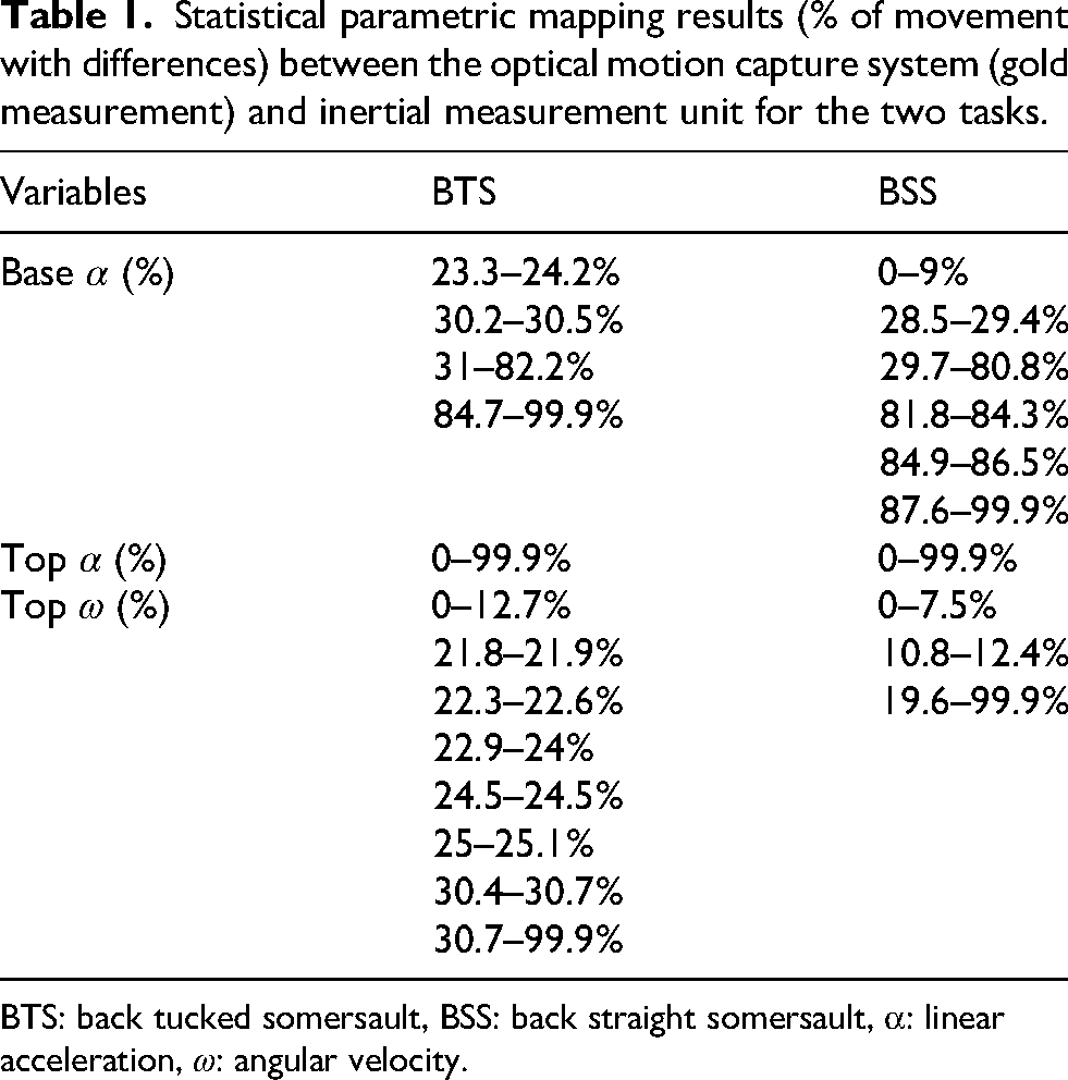
BTS: back tucked somersault, BSS: back straight somersault, α: linear acceleration, ω: angular velocity.
Figures 2 and 3 depict the α ensemble averages curves for both tasks, and Figure 4 shows the ω ensemble averages in the rotation axis of the top gymnast. Figure 2 reveals greater amplitude in the curves extracted from the optical MOCAP, with two peaks, while IMU curves show motion at 60–95%. The top gymnast data shows a peak at the end of the motion in both tasks (Figure 3), which corresponds to the landing. Figure 4 illustrates that the top's ω measured by the IMU exhibits a sign inversion compared to the optical MOCAP data.
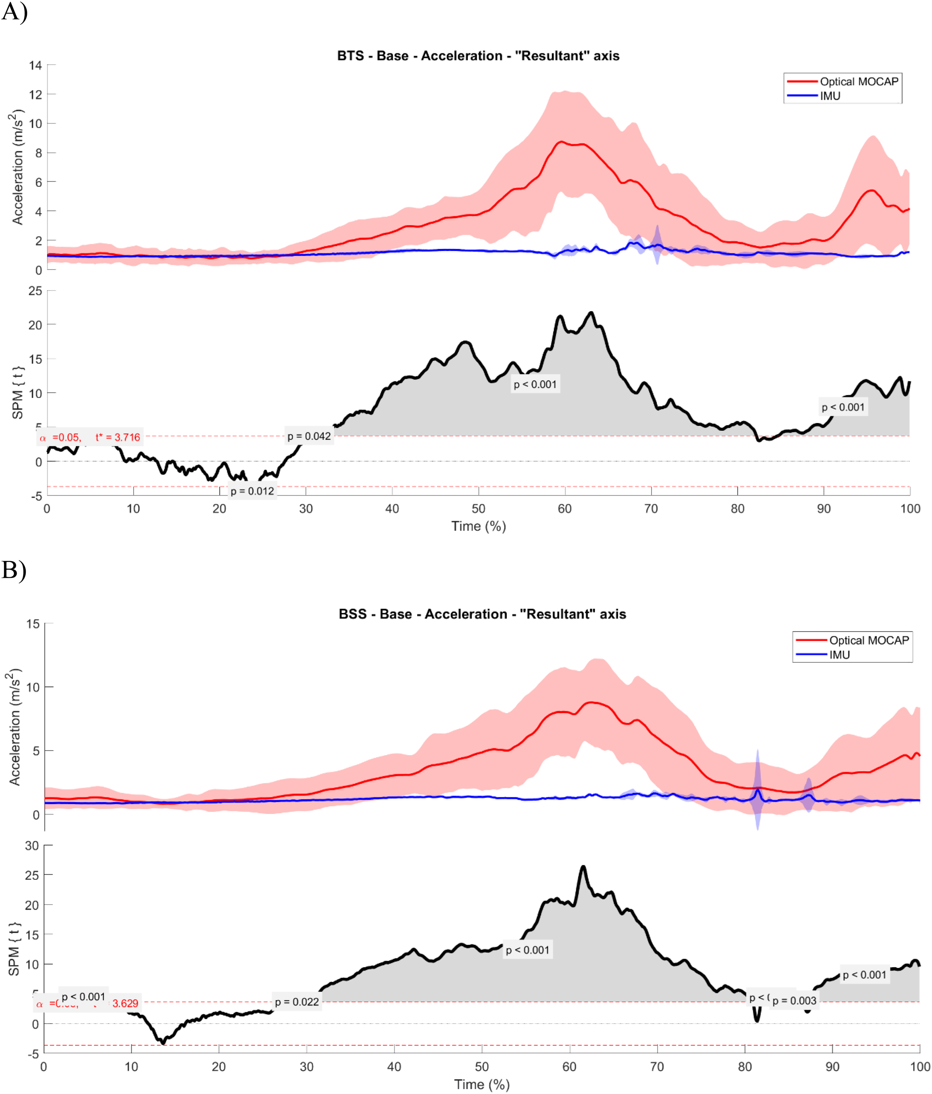
A. Statistical Parametric Mapping (SPM) results from the acceleration of the base gymnast during the back tucked somersault, B. SPM results from the acceleration of the base gymnast during the back straight somersault.
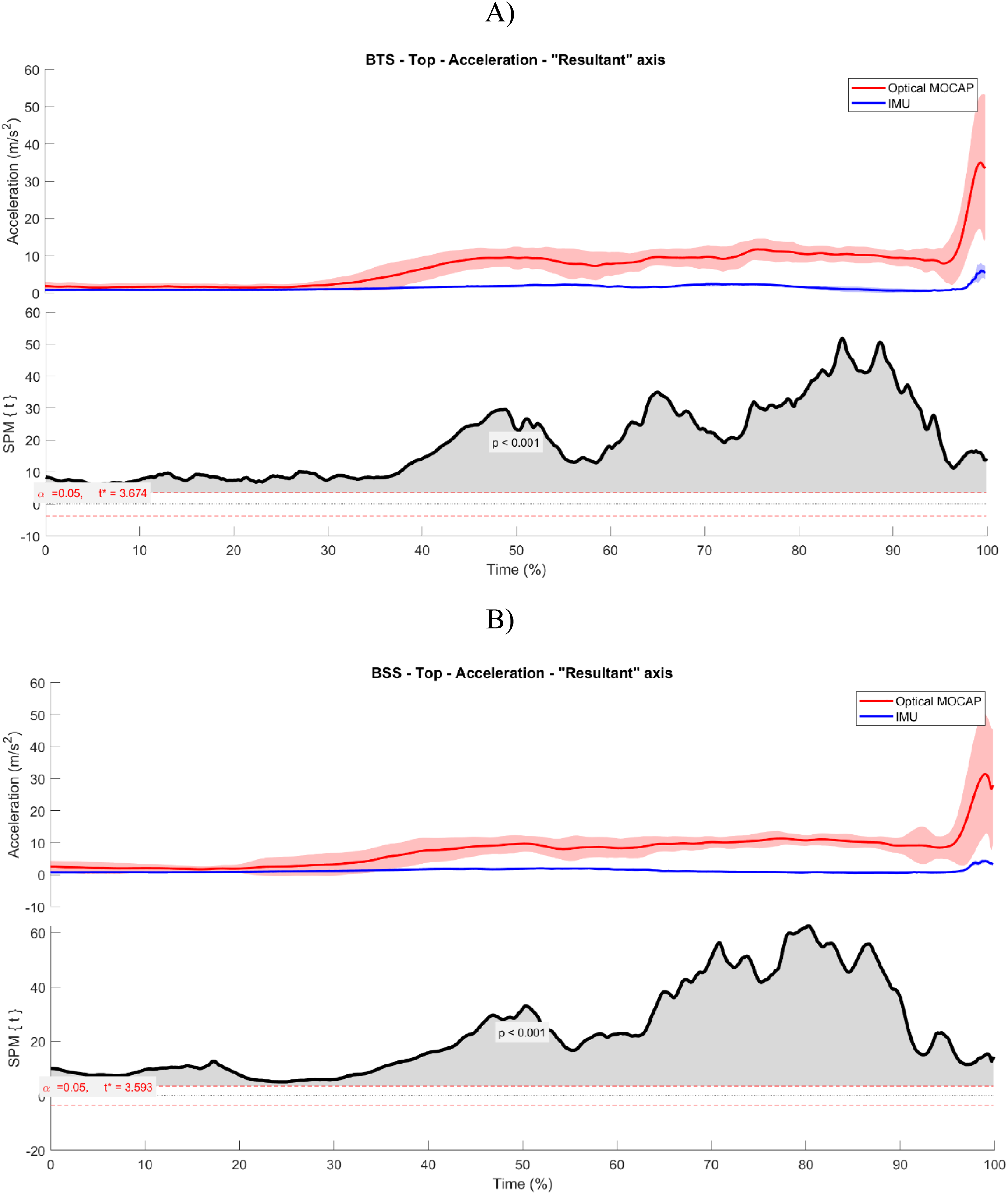
A. Statistical Parametric Mapping (SPM) results from the resultant of acceleration of the top gymnast during the back tucked somersault, B. SPM results from the resultant of acceleration of the top gymnast during the back straight somersault.
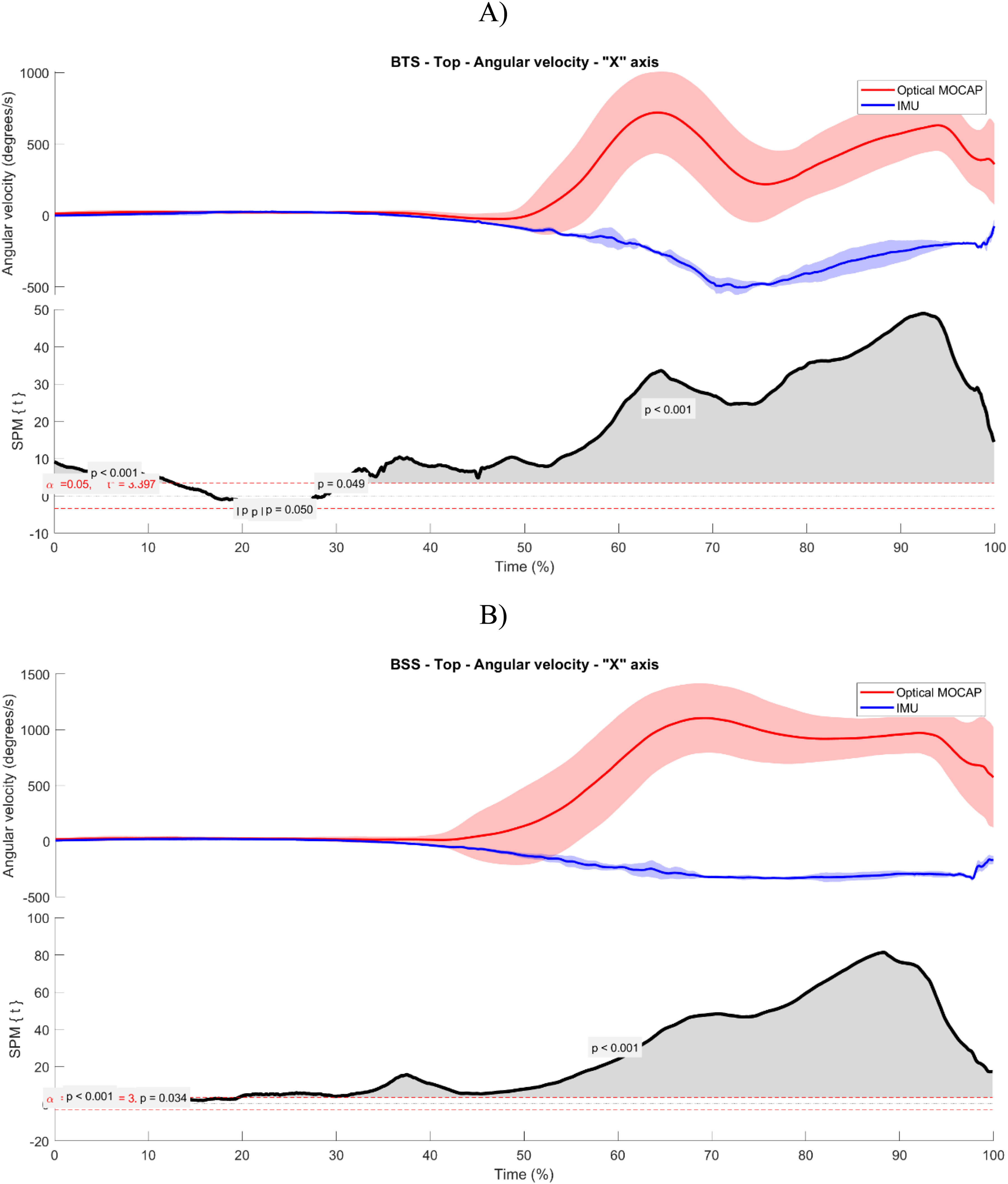
A. Statistical Parametric Mapping (SPM) results from the angular velocity of the top gymnast during the back tucked somersault, B. SPM results from the angular velocity of the top gymnast during the back straight somersault.
Discussion
Can a single IMU placed on the sacrum of acrobatic gymnasts accurately represent their CoM? This work has compared the CoM α calculated from an optical MOCAP system data and from an IMU placed in the sacrum of gymnasts. Approximately 100% of the top gymnasts’ motion was different between methods. For base gymnasts, α derived from MOCAP and IMU was similar during a few time windows (for BTS, 0–23.3%, 24.2%-30.2% and 82.2–84.7, and for BSS, 9%-28.5%). For the top ω, IMU data appears inverted relative to the optical MOCAP. The hypothesis formulated for this work is consequently rejected, since there is no statistical evidence to support the similarity of both methods.
IMUs are factory-calibrated, meaning they undergo rigorous procedures to correct sensor bias, scale factors, and alignment before being shipped. The base gymnast throws the top gymnast, which includes a countermovement (downward and upward motion), so the IMU orientation was not majorly affected. However, the top gymnasts performed a CMJ, followed by rotations: moving downward, upward, rotating and moving downward again, affecting the IMU orientation. To reduce directional bias and avoid errors from misalignment between the IMU and the optical MOCAP coordinate systems, we used the α resultant, which combines motion across all three axes. For the top gymnast ω, the mediolateral rotation axis was specifically analyzed as it best represents the primary rotational movement.
For both tasks, the base's optical MOCAP data shows two peaks, associated with the throw propulsion (α ∼ 8 m/s2) and the landing (α ∼ 4 m/s2) phases (Figure 3). During 60–95% of the base motion, the IMU measured highest α, probably because during this time window the base performs the throw propulsion, when the higher α is produced. However, the highest α was about 2–3 m/s2 and no motion was detected for the base landing. A single IMU attached to the lower back of a rider during non-seated cycling revealed that IMU substantially overestimates the model's CoM, especially at greater ranges of vertical displacement. 20 Alanen, Räisänen 4 also reported that IMU kinetic or kinematic variables show inconsistency and overestimation. These findings are not aligned with the present study since the IMU underestimated the optical MOCAP α, perhaps because of the tasks difference or specificity.
Park and Yoon 21 showed that IMU-based systems are useful for assessing spatiotemporal variables and calculating ranges of motion; but differences in discrete variables may be over or underestimated. In parallel, the velocity curves during breaststroke swimming showed an underestimation of velocity values by the IMU compared to the values of a speedometer, which can be seen mostly at higher swimming velocities. 22 Compared to force plate-based CoM estimation, IMUs tend to either overestimate or underestimate CoM position depending on the task. Specifically, greater underestimation has been observed along the vertical axis during tasks such as full squats, half squats, and mediolateral or internal–external swaying, whereas overestimation is more common during jumping tasks. 10 Our results also presented such a lack of precision according to the task. Probably, MOCAP and IMU provide complementary information. Further studies are necessary with different tasks from different sports and contexts to confirm this tendency.
Since the base accelerates the top gymnast, higher top CoM α is expected (∼ 10 m/s2). The optical MOCAP data presented a 40 m/s2 peak at the end of the motion, which is associated with the top gymnast's landing. Peak ground reaction forces were accurately predicted through raw accelerometry data for ankle, lower back and hip accelerometer placements. 23 However, in the present study, the IMU did not seem to measure the α of the top gymnast during the propulsive and rotational motions, or the top and base gymnast's motions were so synchronized that the top moved in a way that reduced the base gymnast's efforts for propulsion. Only the top gymnast's landing influenced the α IMU curve (∼ 5 m/s2). This method was also used to measure upper and lower limb loading in gymnastics; however, this work has evaluated inter-trial variability between raw and filtered data, using two IMUs for the upper and two IMUs for the lower limbs, while upper and lower back IMUs remained in place for both cases. 2 The IMU α resultant peak measures showed very good inter-trial reliability and the forearm- and tibia-mounted IMUs showed improved reliability (very good reliability) compared to upper and lower back positions (good reliability). 2 While the referred IMU data was not compared with other kinemetric outcomes, these findings highlight the reliability of the proposed method and its potential to accurately aid the coaching process.
Regarding the top's ω, there are some time windows when both methods are similar: 12.7% - 21.8% and 25.1% - 30.4% for BTS, and 7.5%-10.8% and 12.4%-19.6% for BSS (Table 1). After 50% of the movement, IMU data suggests movement in opposite direction compared with optical MOCAP (Figure 4), considering that IMU measures the ω relative to their own coordinate system, which rotates with the gymnast, while the optical MOCAP uses a fixed, global reference frame. Compared with high-speed video, data from sprinters using IMUs on their feet, shanks, thighs, pelvis and trunk showed multiple correlation coefficients of > .99 for the ω of the thigh and shank but low for the pelvis and trunk (.13– .66) and limits of agreement were ≤ 57°.s−1 (≤ 93°.s−1). 24 In tennis, a conference paper showed high correlation coefficients and comparable ω between IMUs and optical MOCAP 25 ; but this work has used four IMU gyroscopes on the trunk, head, arm and forearm. Although studies suggest the ω as an additional input, 7 specially to examine coordination and performance since this variable is directly measured by the IMUs and would probably provide more accurate results, 26 we only found one study using ω measurements with one IMU placed in the sacrum of swimmers. 9 However, this data was not compared with a gold measurement system.
In terms of information about acrobatic gymnasts’ performance provided by a single IMU, our findings suggest that IMU data detects α about the base's propulsive motion and the top gymnast's landing, and in the ω of the top (despite in the opposite direction); however, the data is underestimated and should be carefully interpreted. Further work is required to understand whether this data is useful, for example using correlations or Bland Altman analyses of values at these time points. A gait analysis using four IMUs (pelvis (body area of the sacrum), thighs, shank, and foot) suggested that IMU data can be used confidently during the stance phase but needs evaluation regarding the swing phase: there were differences in the discrete and continuous variables of the knee and ankle joints between IMUs and MOCAP. 21 While sacrum displacement is a valid measure for sideways CoM displacement, the systematic amplitude and timing differences between an IMU placed in the sacrum and CoM displacement in the anteroposterior and vertical directions inhibited the exact calculation of energy fluctuations. 5 Indeed, our results also present a small-time delay between the optical MOCAP data and the IMU: IMU is delayed in relation to optical MOCAP (Figure 2 and 3). Therefore, coaches and researchers should carefully interpret the findings and practical implications for training using IMUs. The underestimation can be problematic for applications that require precise data, such as performance optimization, and while IMUs may work well for general motion tracking, they may require careful validation when measuring high-precision events like jump heights. 10
Although it is not the goal of this work, it is important to provide some considerations about the sensitivity of the optical MOCAP and IMU systems to the kinematic differences between the BTS and BSS tasks. As illustrated in Figure 4, the slope of the ω curve varies between the two tasks: the BSS task exhibits a longer duration with a more gradual slope, whereas the BTS task is shorter but demonstrates a more pronounced initial acceleration, likely followed by deceleration as the gymnast transitions to a straight body position. This variation underscores a notable discrepancy between the optical MOCAP and IMU measurements. In alignment with the primary objective of this study, as stated in the title - ‘Can an inertial measurement unit be used as a field tool for Acrobatic Gymnasts training?’ - this line of discussion is directly related to the overarching goal. Two main perspectives emerge in addressing this question. The first concerns the precision, accuracy, and reliability of the IMU compared to the MOCAP system. The second perspective relates to the practical applicability and usefulness of the IMU in providing relevant information during the training of acrobatic gymnastics skills involving an aerial phase. From this latter perspective, MOCAP provides more precise kinematic data, revealing distinct differences in the curves that characterize the two acrobatic skills analyzed, which vary in difficulty due to differences in the top's body position during transverse axis rotation. The IMU is not sensitive to the kinematic phases (speeds, accelerations, decelerations) that occur during the top's flight in any case, nor to the differences between the two skills analyzed with different difficulties.
Although both systems are validated, their distinct accuracy limits must be acknowledged. IMUs excel in capturing local accelerations of a segment, though they may be less dependable for reconstructing global trajectories. 27 The observed differences are a consequence of their distinct acquisition and processing methods. IMUs accuracy can be task-dependent and sensitive to sensor placement errors. Using multiple IMUs can enhance accuracy: a setup with three IMUs indicated high precision for CoM velocity estimation. 28
One limitation of this study is the small sample size, which reflects the inherent challenges of assessing high-performance gymnasts. Each pair performed 10 trials per task, resulting in a total of 210 trials and enhancing the robustness of our dataset. Our primary objective was to evaluate procedures that coaches could easily replicate during training. To address discrepancies in sampling frequencies between methods, we prioritized resampling techniques to ensure data comparability. Another limitation lies in the use of filtered data since filtering may hinder direct replication during training contexts and did not improve the agreement between the two methods. The optical MOCAP system uses filtering to accurately capture the aerial phase of the top gymnast, so the IMU data were also filtered to enable a more valid comparison between the two systems. Additionally, although both systems were synchronized, small timing discrepancies cannot be entirely ruled out and may contribute to variability in the temporal alignment of data.
A final limitation relates to the method used for calculating ω in the MOCAP data. While ω was directly available from the gyroscope in the IMU, it was estimated from the CoM L and CoM I in the MOCAP data using a custom MATLAB script. These values were computed based on segmental data provided by Visual3D. However, the model used to estimate these quantities was limited in scope: it only included the pelvis and lower limb segments. Contributions from the thorax, upper limbs, and head were not considered. Therefore, the MOCAP-derived ω reflects only partial body dynamics, which may limit the comparability with the whole-body measurements from the IMU. Despite these limitations, our methodological approach aims to balance scientific rigor with practical applicability for real-world training environments. Future research may explore integrating additional sensors to improve the reliability of CoM estimations, as well as examining tasks across diverse sports and contexts to enhance the generalizability of the findings. Finally, incorporating full-body models may enhance the fidelity of the biomechanical estimations and reduce discrepancies between measurement systems.
Conclusions
The only way for coaches to integrate IMU technology into training is by keeping the procedure simple and without compromising valuable practice time: placing one IMU in the sacrum would make the process very straightforward. However, there is no statistical evidence to support the use of a single IMU placed on the sacrum to obtain reliable data about both gymnasts CoM α and top's ω, as well as to acquire relevant information with practical implications for partner-assisted flight tasks from acrobatic gymnastics. Although a few areas reported similarities between both methods, these are likely of no use due to the large periods of large significant differences.
Footnotes
Acknowledgements
We thank all the gymnasts, coaches, and clubs for their invaluable time and commitment to this study.
Funding
The authors disclosed receipt of the following financial support for the research, authorship, and/or publication of this article: This work is financed by national funds through FCT - Fundação para a Ciência e a Tecnologia, I.P., within the scope of the project/support 2021.06653.BD* - Center for Research, Training and Intervention in Sport. The grant was endorsed to the first author (![]() ).
).
Declaration of Conflicting Interests
The authors declared no potential conflicts of interest with respect to the research, authorship, and/or publication of this article.