
Abstract
Nuclear power plant is completely independent of air and has high power density, which improves unmanned marine vehicle maneuvering performance, maximum speed, and concealment. The supercritical carbon dioxide-cooled reactor system that has the advantages of compact system and high cycle efficiency is a promising energy conversion system candidate for generation IV reactors. However, due to the dramatic variations of supercritical fluid thermophysical properties, the operation of supercritical carbon dioxide-cooled reactor system is complex and it is difficult to control it. In this article, a mathematical model of supercritical carbon dioxide-cooled reactor system was established using the modified RELAP5 code, and two traditional coordination control schemes were used to study the system operation characteristics under load drop transient condition. Each key system parameter response characteristics was investigated. Finally, based on the research results, an optimized operation scheme that was proved to have better system control effect was proposed.
Introduction
Unmanned marine vehicle (UMV), a complex unmanned system, has multiple functions such as environmental perception, dynamic decision-making and planning, behavior control, and power adapter. 1 Energy is one of the main factors limiting UMV operations by limiting its endurance, speed, operating depth, mission load, and so on. 2 A UMV works by remote control or autonomous control to achieve the assignments such as marine environment observation, target detection, salvage and lifesaving, hydrological survey, and so on. 3 –5 UMV energy power system (referred to as energy system) provides power source for UMV motion and energy for equipment, instrument, and mission loads. Energy system is the basic system of UMV, which accounts for the majority of the total UMV mass or total volume. Its principle design and working performance play a very significant role in UMV mission.
Traditional UMV energy sources include lead–acid batteries, cadmium–nickel batteries, and silver–zinc batteries. 6 Lead–acid batteries have some advantages in terms of technology and cost, but their disadvantages such as low energy and short cycle life are prominent. They have been eliminated from the UMV in service in the United States. Compared with lead–acid batteries, nickel–cadmium and nickel–metal hydride batteries do not improve their energy ratio significantly. With high current discharge, their life is slightly better than that of lead–acid batteries. They can maintain UMV voyage for approximately 4–12 h, but their cost performance is not high. Silver–zinc batteries have long charging time, short service life, poor low-temperature performance, and high maintenance cost. They are two to three times more energy than lead–acid batteries, mainly used for light and medium UMV. Lithium batteries have the advantages of high voltage, high specific energy, long cycle life, good safety performance, small self-discharge, rapid charge and discharge, high operating temperature range, no reactant discharge, and so on and have gradually replaced lead–acid batteries and cadmium–nickel batteries, which become the mainstream of power batteries. In theory, lithium batteries are suitable for all types of UMV, but they have a capacity that slowly decays, an intolerance to overcharge and an intolerance to overdischarge, so multiple protection mechanisms are required. From the perspective of the current development direction of UMV field, the future demand of UMV for energy system is mainly compact structure size and high energy density, so as to provide higher speed and greater endurance for the vehicle. 7,8 Nuclear power plant is completely independent of air and has high power density, which improves UMV maneuvering performance, maximum speed, and concealment. 9 Therefore, it can be used as an energy system for large or ultra-large UMV. 10,11 The supercritical carbon dioxide (SCO2)-cooled reactor system is compact and suitable for small nuclear power systems, providing reliable power supply for UMV.
The SCO2 Brayton cycle was first proposed by Feher 12 in the 1960s but was not fully developed in view of the limitations of the industrial technology at the time. With the development of industrial technology, the SCO2 Brayton cycle has attracted attention again. Due to the wide heat source temperature available, many studies have been carried out on SCO2 Brayton cycle applied lto coal-fired, 13 solar, 14,15 and nuclear power generation. 16,17 Among them, the reactor coupled with SCO2 Brayton cycle is a promising energy conversion system candidate for generation IV reactors. 18
Based on the special thermophysical properties of supercritical fluid as shown in Figure 1, the SCO2-cooled reactor system has advantage in simplicity, compactness, security, and economy. The specific heat (Cp ) of SCO2 is higher than that of traditional working fluids such as water and helium, which makes the heat exchange equipment using SCO2 as working fluid more efficient and compact. More importantly, the miniaturization of turbomachinery can be realized by taking advantages of the high-dramatic density and the well-compressed characteristics of SCO2, 19 which meets the actual demand of special applications such as in aerospace and deep-sea industry. Dostal et al. 20,21 proposed the SCO2 recompression Brayton cycle, which realizes the efficient utilization of heat and avoids the recuperator pinch-point problem by flow split and recompressing compressor. Meanwhile, Hejzlar et al. 19 also carried out 2400 MWth SCO2-cooled direct-cycle gas-cooled fast reactor (GFR) design based on this cycle. The preconceptual design of SCO2-cooled integrated multi-modular fast reactor consisting of seven self-consist subcritical modules was completed by Vishal Patel et al. 22,23 And a concept design of SCO2-cooled small modular reactor (SMR) operating at isolated microgrid region was suggested by Seong Gu Kim et al. 24,25 In addition, the key equipment in SCO2-cooled reactor system was widely studied. Li et al. 26 and Kruizenga et al. 27 researched the flow and overall heat transfer characteristics of SCO2 in printed circuit heat exchanger (PCHE) microchannels through experimental and computational fluid dynamics (CFD) methods. Lee et al. 28 developed the SCO2 turbomachine design and analysis code for the water-cooled small modular reactor application. However, few simulation research and coordination control scheme design were performed. Idaho National Laboratory expanded the function of RELAP5-3D for next generation nuclear plant simulation and analysis. 29 –31 The GFR proposed by Massachusetts Institute of Technology (MIT) 19 and nuclear fusion reactor designed under TECNO_FUS 32 was modeled and simulated by RELAP5-3D. The calculation capacity of the RELAP5-3D was verified and several typical transients were simulated to study the thermal-hydraulic characteristics of the SCO2-cooled reactor system. The gas system transient analysis code GAMMA was verified by the experimental data of SCO2 pressurizing experiment by Seong Jun Bae et al. 33 And they believed that the code had the potential for being used in a larger scale SCO2 power system. Du et al. 34 comparatively analyzed the off-design performance of a transcritical carbon dioxide power cycle by different operation methods. And a novel method for the optimal operation was proposed to obtain maximum system efficiency.

SCO2 thermophysical properties near the pseudocritical temperature at 8 MPa. SCO2: supercritical carbon dioxide. 35
Based on the above discussion, it can be found that the study of SCO2-cooled reactor system was mostly at the design stage. The detailed mechanism research was only carried out for the single key equipment. There is a lack of research on the comprehensive operation characteristics of the whole system. Similarly, few tools and methods to carry out the study of SCO2-cooled reactor system operation characteristics. Moreover, the special thermophysical properties of SCO2 in Figure 1 make the reactor system operating characteristics more complex than that of traditional working fluids, especially the control system. Therefore, the previous research needs to be further improved to understand the operation characteristic of SCO2-cooled reactor system under coordination control scheme.
Based on above description, a modified RELAP5 code was used for SCO2-cooled reactor system modeling and simulation calculation. The key system parameters response characteristics in traditional operation schemes under load drop transient condition were investigated. Besides, an optimized control scheme was proposed based on the simulation analysis results.
Modified RELAP5 and simulated system description
RELAP5 modification and validation
The RELAP5 code is the best-estimate system analysis code based on a two-fluid model for two-phase flows. 36 To study the operating characteristics of SCO2-cooled reactor system under coordination control scheme, a modified RELAP5 code was used to establish the system model. The addition of SCO2 thermophysical properties, the development of compressor model, the update of turbine model, the modification of heat exchanger model, and the change of thermal-hydraulic correlations were performed during the RELAP5 function expansion, which referred to Davis Cliff et al.’s study 37 and were not described in detail in this article.
The GFR designed by MIT 19 was modeled to prove the simulation capability of the modified RELAP5 developed in this article. The temperature–pressure charts of MIT-GFR calculated by the modified RELAP5 and designed by MIT are compared in Figure 2. The result shows that the simulation results of each position in the Bryton cycle are in good agreement with the design results.

Comparisons of T-P chart between calculation results by modified RELAP5 and MIT design. T-P: temperature–pressure.
System description and nodalization of SCO2 recompression Brayton cycle
One megawatt electrical SCO2-cooled reactor system was designed using the method proposed by Zhang et al. 38 and the major design parameters are presented in Table 1. The Brayton cycle comprised a single-stage radial type turbomachinery, all of which are coupled to a single shaft. The heat exchangers are designed as the PCHE, a promising candidate for recuperator in SCO2 Brayton cycle.
Design parameters of SCO2-cooled reactor system.

SCO2: supercritical carbon dioxide.
The SCO2-cooled reactor coupled with recompression Brayton cycle as shown in Figure 3 was chosen for operation characteristic study under coordination control scheme. And the nodalization is shown in Figure 4. The SCO2 enters the turbine (component 315) to generate power after heated in the reactor (component 113, 115, 117P, and 118). The energy of exhaust gas is recovered via recuperator (component 330P and 340P). The SCO2 then splits into two parts before the precooler. One part is cooled through the precooler and compressed in main compressor (component 360P and 365). The other part is compressed to a higher temperature and pressure directly in recompressing compressor (component 350), which reduces the heat rejection in precooler. The SCO2 at the outlet of main compressor flows through the low temperature recuperator (LTR) and merges with the other part of SCO2 at the recompressing compressor outlet (component 375P). The combined working fluid is preheated in the high temperature recuperator (HTR) and returns to the reactor for a complete energy conversion system cycle (component 385P). The efficiency of this reactor system is improved by introducing a recompressing compressor, which can also avoid the pinch-point problem in the recuperator caused by the varied SCO2 thermophysical properties.

Layout of SCO2-cooled reactor coupled with recompression Brayton cycle. SCO2: supercritical carbon dioxide.
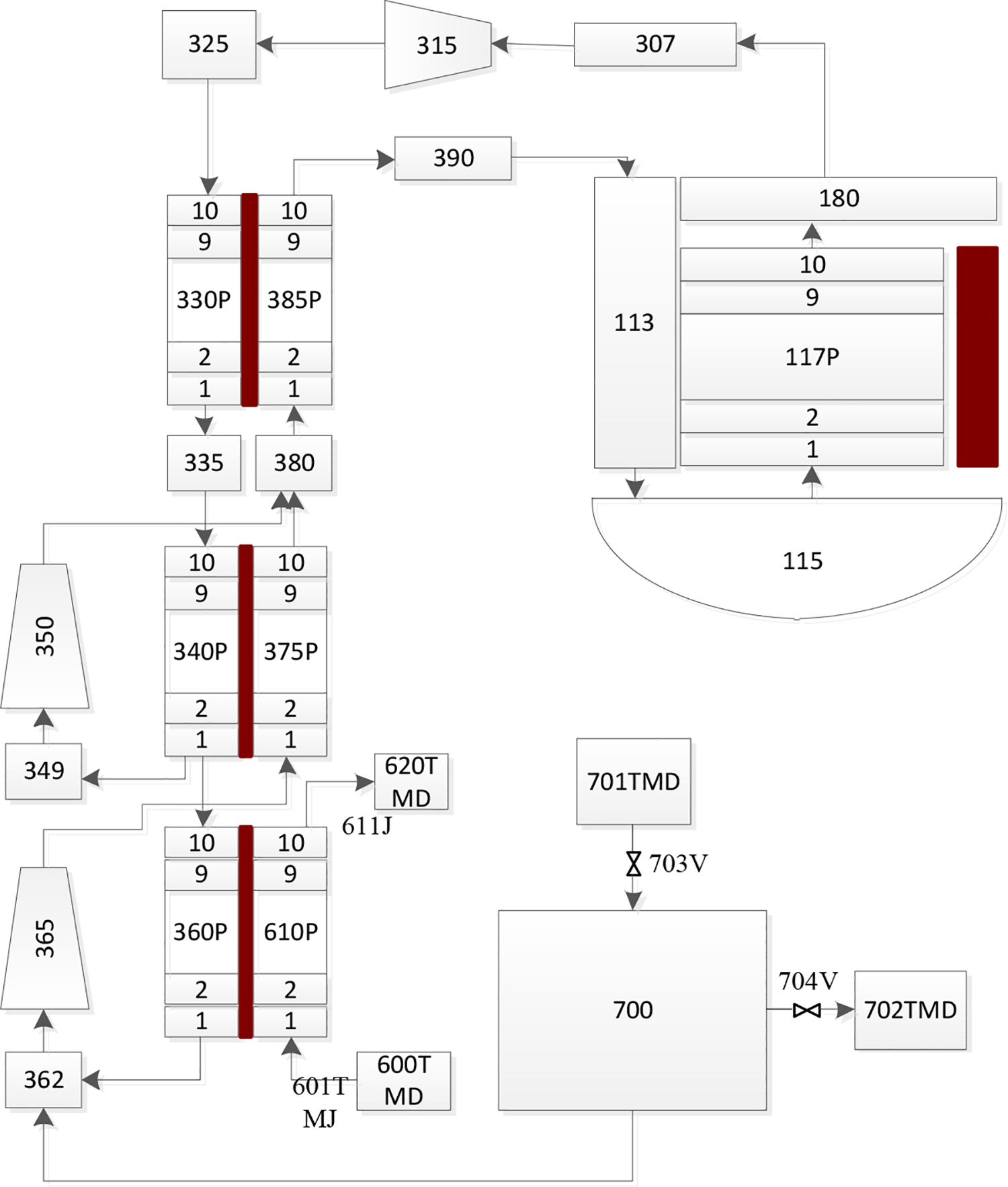
The RELAP5 nodalization of SCO2-cooled reactor system. SCO2: supercritical carbon dioxide.
Nodalization validation
The comparisons of steady-state calculated results by the modified RELAP5 with the design parameters of SCO2-cooled reactor system are presented in Table 2. It can be seen that the calculation method using the modified REALP5 proposed above can simulate the SCO2-cooled reactor system accurately.
Comparisons of calculated results by the modified RELAP5 with design parameters of SCO2-cooled reactor system.

SCO2: supercritical carbon dioxide.
Coordination control schemes
Proportion integration differentiation (PID) control method was applied to key parameters control for stable operation of the SCO2-cooled reactor system. The constant main loop mass flow and constant reactor outlet temperature are basic stable operation control schemes of reactor system. The two steady-state operation control schemes are composed of reactor power control system, circular pressure control system, precooler cooling flow control system, and circular flow control system.
Reactor power control system
The reactor power control system requires that when the load of the Brayton cycle changes, the reactor power can automatically track the change of the load to match the generation load. Therefore, the reactor power is set as the control parameter and the generation load is set as the control target. When the actual load of the turbine does not match the set load, the actual load is taken as the input signal and compared with the load set value. The differential signal is sent to the reactor power control system based on the PID method. By changing the core reactivity, the reactor power is increased or reduced to balance with the turbine load as shown in Figure 5.

Reactor power control system.
Circular pressure control system
The purpose of circular pressure control system is to ensure the constant inlet pressure of the main compressor. When the circulation pressure does not match the design value, the actual circulation pressure is compared with the design value and taken as the input signal for circular pressure control system. The differential signal controls the opening of the relief valve and the booster valve through the proportional calculation to stabilize the circulation pressure. When the circulation pressure increases, the relief valve opens and discharges part of the SCO2 in the circulation to the external system, thus reducing the Brayton circulation pressure. When the circulating pressure decreases, the boost valve opens and fills the pressurized SCO2 in the external system into the Brayton cycle to increase the system pressure.
The process diagram of the circular pressure control system is shown in Figures 6 and 7, where Pwerf represents the system pressure setting value. When the pressure deviation is within the range of −0.1 to 0.1 MPa, the relief valve and the booster valve are closed. When the pressure deviation is within the range of −0.3 to −0.1 MPa, the relief valve is opened proportionally. When the pressure deviation reaches −0.3 MPa, the opening of the relief valve reaches the maximum. When the pressure deviation is in the range of 0.1–0.3 MPa, the booster valve is opened proportionally. And when the pressure deviation reaches 0.3 MPa, the opening of booster valve reaches the maximum.

Circular pressure control system.

Valves response baed on the circular pressure control system.
Precooler cooling flow control system
The purpose of the precooler cooling flow control system is to ensure that the temperature and the density of the working fluid at the main compressor inlet are in the design state. The precooler cooling flow control system is combined with the circular pressure control system to ensure that the working fluid at the main compressor inlet is always in a supercritical state and to ensure the stable operation of the main compressor. Therefore, the SCO2 temperature at the inlet of the main compressor is taken as the control target.
The SCO2 temperature at the inlet of the main compressor can be changed by changing the cooling water flow rate of the precooler. When the SCO2 temperature at the inlet of the main compressor does not match the design value, the SCO2 temperature is taken as the input signal and compared with the design temperature. The differential signal adjusts the frequency converter of the cooling water pump or the cooling water flow regulating valve through the proportional integral calculation, so as to adjust the cooling water flow rate of the precooler to meet the requirements of the main compressor inlet temperature as shown in Figure 8.

Precooler cooling flow control system.
Circular flow control system
The main compressor is controlled by the variable frequency motor, and the compressor rotate speed is taken as the control parameter. In the constant flow operation scheme, the circular flow is taken as the target parameter. When the actual flow does not match the design flow, the actual flow is taken as the input signal and compared with the design value. The differential signal calculated by PID method is used to change the rotate speed of the main compressor. As a result, the circular flow is increased or decreased to match the set value as shown in Figure 9(a).

Circular flow control system: (a) circular flow control system in constant flow operation scheme, (b) circular flow control system in constant reactor outlet temperature operation scheme.
In constant reactor outlet temperature operation scheme, the reactor outlet temperature is taken as the target parameter, as shown in Figure 9(b). When the reactor outlet temperature does not match with the design value, the reactor outlet temperature is taken as the input signal and compared with the design value. The differential signal is calculated by PID method and used in the main compressor rotate speed control. The circular flow is increased or decreased by changing the main compressor rotate speed. The core outlet temperature is indirectly affected to match the set value.
Result and discussion
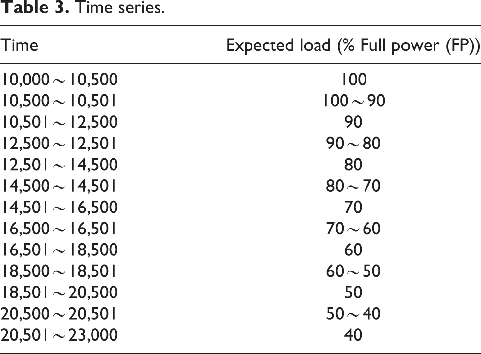
Based on the above control systems, the control and reactor safety characteristics of the SCO2-cooled reactor system at different loads were studied in this article. The specific time series are presented in Table 3. The system is stable at 10,000 s and gradually reduces from 100% load to 40% load in the expected regulation time.
Time series.
Constant flow operation scheme
Figures 10 to 14 show the calculation results of key system parameter response characteristics in constant flow operation scheme under different loads. And the transient process of the first load reduction is analyzed as an example in the following.

Dynamic response during the first load reduction process.

Cooling water flow and main compressor inlet temperature response during the first load reduction process.

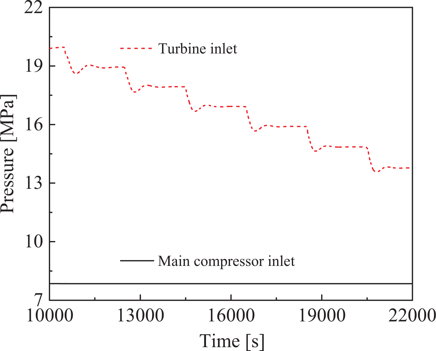
Pressure response during the first load reduction process.
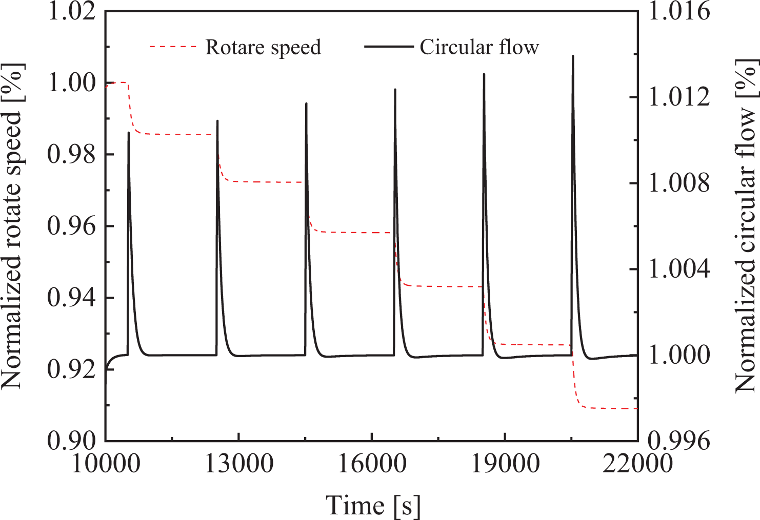
Rotate speed and circular flow response during the first load reduction process.

SCO2-cooled reactor system thermal efficiency response during the load reduction process. SCO2: supercritical carbon dioxide.
When the generation load drops, the reactor power responds immediately and reaches a new steady state after about 600 s. The reactor power decreases from 100% to 93.87% in Figure 10. And the Brayton power generation load drops rapidly from 100% to 90% in about 20 s and reaches stability. Similarly, the reactor outlet temperature reaches a new steady-state value about 200 s after the load drops. The reactor outlet temperature sharply decreased from 925.89 K to 877.49 K.
The cooling water flow of the precooler decreases to 97% and tends to be stable about 1000 s after the load change in Figure 11. The disturbance of main compressor inlet temperature is less than 0.1% when load change and then restored to the design value after about 250 s, which proves that the main compressor inlet temperature keeps constant in Figure 11 and the precooler cooling flow control system has a good effect on the compressor inlet temperature control.
Brayton cycle pressure is disturbed at the moment of load change and drops to 7.85 MPa after 100 s. At the same time, the opening of the booster valve restrains the decrease of the circular pressure and keeps it constant at 7.85 MPa in Figure 12, which proves that the main compressor inlet pressure remains constant and the circular pressure control system has a good effect on the system pressure control.
The circular flow control system starts when the circulation flow rises rapidly at the moment of load change, which causes the rotate speed of the main compressor decreases and reaches a stable value with the circular flow after about 200 s. Under the intervention of circular flow control system, the rotate speed drops to 98.55% of the design rotate speed and the circular flow is constant at 11.66 kg/s as shown in Figure 13.
At the same time, with the gradual decrease in load, the SCO2-cooled reactor system thermal efficiency also decreases as shown in Figure 14.
It can be seen from the above analysis that the key parameters of the SCO2-cooled reactor system have a small fluctuation or are in the safe range during the whole transient process. The reactor control systems have good effect and the ability to ensure the safety of the system operation.
Constant reactor outlet temperature operation scheme
Figures 15 to 18 show the calculation results of key system parameter response characteristics in constant reactor outlet temperature operation scheme under different loads. Similarly, the transient process of the first load reduction is analyzed as an example in the following.

Dynamic response during the first load reduction process.

Cooling water flow and main compressor inlet temperature response during the first load reduction process.
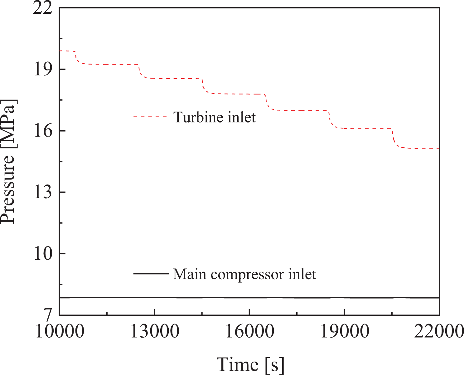
Pressure response during the first load reduction process.
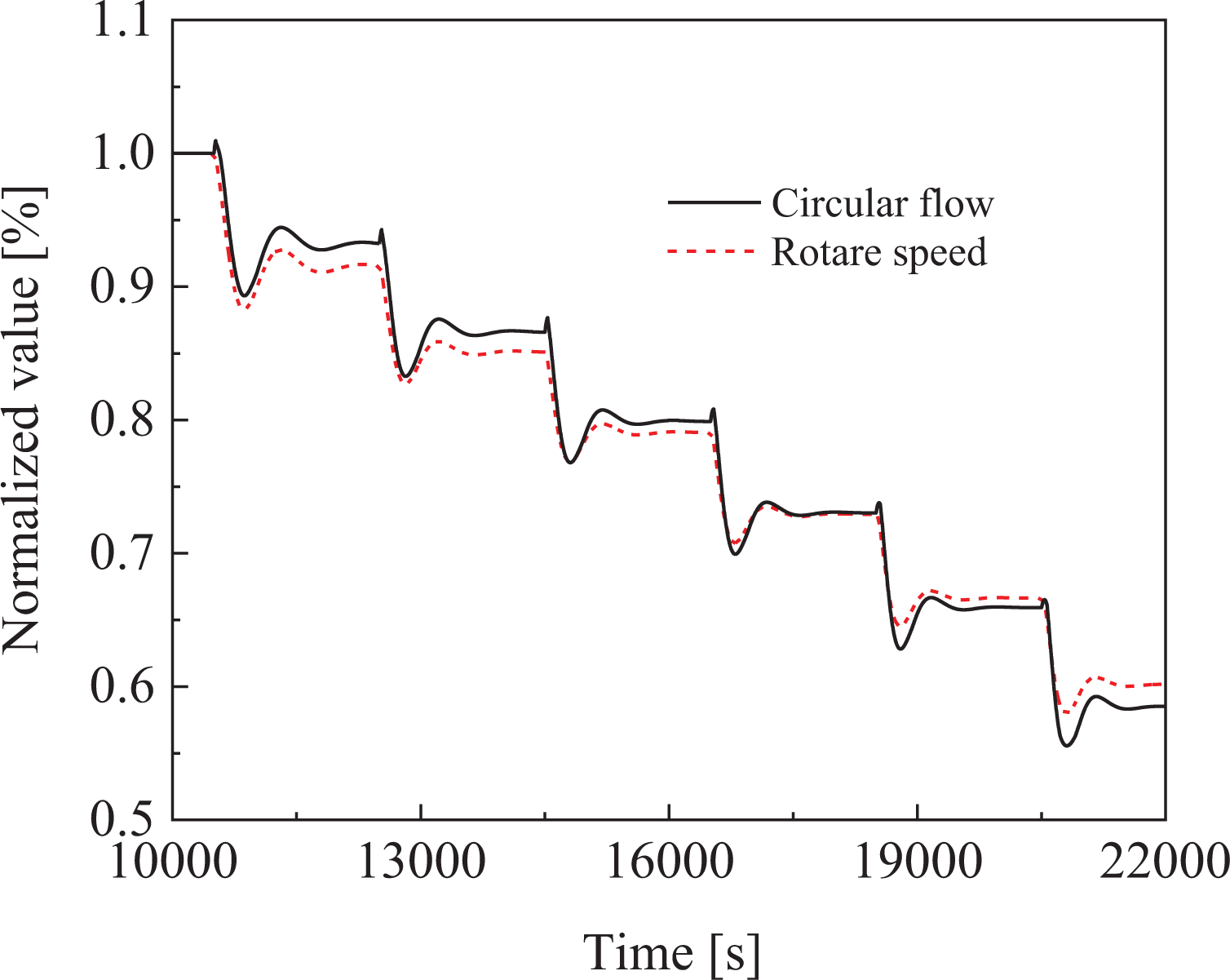
Rotate speed and circular flow response during the first load reduction process.
Compared with the characteristics of previous control strategy, the reactor power response is slower and reaches a new steady (89.86% of full power) state after about 1000 s. Nevertheless, the Brayton power generation load drops rapidly from 100% to 90% in about 20 s and reaches stability. Under the constant reactor outlet temperature operation scheme, the reactor outlet temperature is constant at the design value after a short-time disturbance in Figure 15.
After the transient occurs, the cooling water flow of precooler tends to be stable after 800 s and drops to 82.75% of the design value. The inlet temperature of the main compressor is disturbed within 0.1% at the moment of load change and then the design value is restored after about 800 s in Figure 16. The precooler cooling flow control system ensures the quality of the main compressor inlet working fluid during the transient process.
The disturbance of circular pressure at the moment of load change causes the opening of relief valve and booster valve successively. The circular pressure control system keeps the system pressure between 7.85 MPa and 7.86 MPa and tends to be stable about 1500 s after the transient in Figure 17.
The different control strategies lead to the circulation flow no longer keep constant after the transient. The circular flow control system reduces the rotate speed of the main compressor and achieves the stability of rotate speed and circular flow after about 1000 s. Specifically, the main compressor rotate speed decreased to 91.58% of the design value, while the system flow rate decreased to 93.24% of the design flow as shown in Figure 18.
Under the constant reactor outlet temperature operation scheme, the key parameters of the SCO2-cooled reactor system fluctuate little or in a safe range in the transient process. The control systems can achieve stable and safe operation of the reactor system. However, compared with the results of constant flow operation scheme, the system parameters stability rate is slower.
Optimized operation scheme
Based on the analysis of the above two operation schemes, the constant flow operation scheme has better system stability and shorter parameters transition time. However, under low load, the lower reactor temperature causes a poorer cycle performance. At the same time, the thermal efficiency of the SCO2-cooled reactor system is high under the constant reactor outlet temperature operation scheme as shown in Figure 19. However, the parameters fluctuate greatly and the transition time is longer. Therefore, combining the two operation schemes, an optimized operation scheme was proposed in this article: the control scheme of setting the compressor operation line.

SCO2-cooled reactor system thermal efficiency response during the load reduction process. SCO2: supercritical carbon dioxide.
The compressor in Brayton cycle should run in the area between the surge line and the choke line as shown in Figure 20. In the constant flow operation scheme, the running point of the main compressor moves downward along the ordinate direction under different loads conditions and gradually approaches the choke line. In the constant reactor outlet temperature operation scheme, the main compressor operation point moves to the lower left as the load decreases and gradually approaches the surge line, which results in the decrease of surge margin. Therefore, the range of load variation is limited by the surge line in this operation scheme. In the optimized operation scheme proposed in this article, the operation line of the main compressor is set as shown in Figure 20. The steady-state operation point of the compressor is always on the preset operation line, which ensures that the compressor has enough surge margin and avoids the occurrence of choke.

Performance diagram and operation line of main compressor.
In the control scheme of setting the compressor operation line, the circular flow control system calculates the demand flow corresponding to the operation line based on the current pressure ratio firstly. Then, the actual flow as the input signal is compared with the demand flow, and the differential signal is input to the control system by PID method. The circular flow control system changes the rotate speed of the main compressor based on the input signal to increase or decrease the cycle flow and finally make it match with the demand flow. The updated circular flow control system principle is exhibited in Figure 21, and Figures 22 to 26 show the calculation results of key system parameter response characteristics in the control scheme of setting the compressor operation line.

Circular flow control system.

Dynamic response during the first load reduction process.

Cooling water flow and main compressor inlet temperature response during the first load reduction process.
Pressure response during the first load reduction process.

Rotate speed and circular flow response during the first load reduction process.

Comparisons of SCO2-cooled reactor system thermal efficiency under different control schemes. SCO2: supercritical carbon dioxide.
When the generation load drops, the reactor power immediately responds and reaches a new steady-state value (92.18% FP) about 300 s later. Meanwhile, the load drops rapidly from 100% to 90% in about 20 s and achieves stability.
The reactor outlet temperature responds immediately when the load drops and reaches a new steady-state value (913.00 K) about 400 s later. Moreover, the cooling water flow of precooler decreased to 91.2% and became stable in about 600 s. The main compressor inlet temperature fluctuates within 0.1% when the transient occurs and then recovers to the design value after about 300 s, which shows that the precooler cooling flow control system ensures a constant compressor inlet temperature.
The interactions of relief valve and booster valve can restrain the fluctuation of system pressure and keep it constant at 7.85 MPa, which proves that the effect of the circular pressure control system is effective.
The system flow rises firstly in the transient process and causes the circular flow control system to start. Then, the rotate speed of the main compressor decreases with the control system intervention and reaches a stable value with the cycle flow together after about 400 s. As a result, the rotate speed drops to 95.96% of the design rotate speed, and the circular flow drops to 96.65% of the design value as shown in Figure 25.
From the above analysis, the control scheme of setting the compressor operation line has the advantages of constant flow operation scheme and constant reactor outlet temperature operation scheme while avoiding the disadvantages of two traditional control schemes. During the whole transient process, the fluctuation of each key parameter of the circulation system is small or within the safe range. The control scheme proposed above can make the SCO2-cooled reactor system more stable and the parameter response faster. At the same time, in the transient process of load reduction, the reactor system has higher thermal efficiency in Figure 26 and wider operation range.
Conclusion
A comprehensive operation characteristic study on SCO2-cooled reactor system, a promising energy conversion system candidate for generation IV reactors, was performed under different coordination control schemes. The SCO2-cooled reactor system models are established and verified by the modified RELAP5 code. The key system parameters response characteristics in constant flow operation scheme and constant reactor outlet temperature operation scheme under load drop transient condition were investigated. Finally, an optimized control scheme was proposed and proved to have better system control effect. The main conclusions are listed in the following. The modified RELAP5 code can accurately realize the modeling and simulation calculation of the SCO2-cooled reactor system. Both constant flow operation scheme and constant reactor outlet temperature operation scheme can realize stable operation of the SCO2-cooled reactor system. However, under low load, the lower reactor temperature causes a poorer cycle performance when the constant flow operation scheme is applied. Meanwhile, the system parameters fluctuate greatly and its transition time is long under constant reactor outlet temperature operation scheme. The control scheme of setting the compressor operation line was proposed. The optimized operation scheme has the advantages of both two traditional control schemes. Meanwhile, during the whole transient process, the optimized control scheme makes the SCO2-cooled reactor system efficient and the its parameters response fast.
Footnotes
Acknowledgements
The authors would like to thank S Yan for valuable discussion and grateful for the funding by grants from the Natural Science Foundation of China (Project No. 51709062), Equipment Preresearch Key Lab Fund (Project No. 6142215180107), and China Postdoctoral Science Foundation (Project No. 2019M651265) in support of the present research. We also thank the anonymous reviewers for improving the quality of this article.
Declaration of conflicting interests
The author(s) declared no potential conflicts of interest with respect to the research, authorship, and/or publication of this article.
Funding
The author(s) disclosed receipt of the following financial support for the research, authorship, and/or publication of this article: This work was supported by Natural Science Foundation of China (51709062); China Postdoctoral Science Foundation (2019M651265); Equipment Preresearch Key Lab Fund (6142215180107).