
Abstract
The purpose of this work is to investigate the possibilities of climbing higher obstacles while maintaining the overall dimensions of a walking robot through design improvements and experiments. An original concept for the design of a walking robot with a minimum number of motors is presented. Geometric and force constraints for overcoming an obstacle and the conditions for maintaining static stability are determined. Experiments for overcoming a vertical obstacle are conducted with a 3D printed model. The 3D printed robot feet with different shapes and materials are used. The results of the experiments are presented graphically as a percentage of success against a baseline model. In this study, a dimensionless index to compare the height of the overcome obstacle and the dimensions of the robot is introduced. It allows to objectively compare the possibilities of overcoming obstacles between various types of mobile robots. Conclusions and guidelines for design improvements are made.
Introduction
Possible applications of walking robots are for working in hazardous and dangerous environments for inspection, rescue operations, movement on uneven terrain, and so on. In general, they move in unstructured environments with varying obstacles. 1 Therefore, their design and control system must allow for avoiding and/or overcoming the obstacles. Mobile robots designed for rescue operations, hazardous environment, or inspection in urban environment encounter a variety of obstacles, often facing problems with climbing stairs. 2,3 Compared to wheel robots, walking robots have more complex design, generally, they have more motors and are slower. 1,3 These robots often have a large number of degrees of freedom. 1,4
The stability of walking robots is a major problem because it determines the conditions under which the robot will not rollover. The stability is divided into two types: dynamic and static. Static stability means that the robot does not need to make any movements to maintain balance. It requires the projection of the center of gravity of the robot to lie on the polygon formed by the support points of the robot’s feet. Statically stable walking means that the robot can be stopped at any point from the gait cycle without rolling over. 1 Two-legged robots usually retain dynamic stability and have a relatively large number of degrees of freedom. 5 –7 They have good capabilities to avoid and overcome obstacles, but they need a complex control system and a lot of energy to power the motors. They have lower reliability due to the large number of mechanical and electronic components. 8 For these reasons, in this work, solutions for walking robots with a simple mechanical and control system that have good functionality in an unstructured environment are presented. There exist experimental two-legged robots that allow for movement while maintaining static stability using the method of zero moment point. 9 Alternative design solutions are investigated with a minimum number of mechanical components 10,11 or using adaptive gait. 12 Changhuan et al. 11 presented a low-budget biped robot with three degrees of freedom, capable of maintaining static stability. Other simple solutions are also investigated, such as passive-dynamic two-legged walking 13 and various designs inspired by nature. 14,15 Friction and adhesion between the robot’s feet and the terrain are essential. 16 The shape and material of the feet are important, they can change the gait and improve traction and the ability to overcome an obstacle. 17 Theoretically and experimentally, the possibility of increasing the height that walking humanoid robots can surmount is studied. 18 It is important for the walking robot to overcome the highest possible obstacle while maintaining the same overall dimensions using as simple as possible mechanical and control systems.
Meneses et al. 19 and Corral et al. 20 discuss the kinematics and dynamics of a quasi-passive two-legged robot that is driven by only one motor. Kinematic and dynamic models of the walking mechanism are presented. These models are used to determine the slippage and select the optimal motor. Different adaptive mobile robots are developed for movement in unstructured environments. A methodology for optimizing the navigation in unstructured environments is proposed by Abad et al. 21
A new design of a walking robot based on a minimalist approach is presented—“Less is more”—Miss Wander Rohe. 22,23 The robot has only two motors, and yet, it can move back and forth by walking to rotate at a random angle, to avoid obstacles or overtake them, and even to climb stairs according to its size. Its control system is also very simple. A 3D printed model of the robot already finds an application in developing specialized games for children with specific needs. 24
Description of the robot
In the present work, the capabilities of the robot called “Big Foot” to overcome obstacles are explored. The design and kinematics of the robot are presented in more detail by Chavdarov and Naydenov. 23 The robot consists of a base (1) on which the body (2) is housed so as to allow rotation about a vertical axis R1 (Figure 1). This rotation is carried out by means of a gear motor (6), whose stator is fixed to the body (2), and the rotor moves the circular base (1). The second rotary motion about axis R2 is designed to perform walking. The mechanism realizing it consists of an electric motor (7) fixed to the body (2), which, by means of a transmission mechanism, rotates the shaft (8), which moves the arms (3). At the end of the arms (3), the feet (4) are mounted. Gears with gear ratio of i = 1 are located in arms (3), so that it maintains a constant orientation of the feet (4) relative to the robot’s body (2). 23 The model is powered by a rechargeable battery, and the control is carried out remotely via Bluetooth communication with a PC or a smartphone. Different variants of the control software are developed using sensors of different types.

(a) Scheme of the robot, (b) 3D printed prototype, and (c) the control software interface.
The two rotations can realize arbitrary angles of rotation and are reversible, making the robot extremely maneuverable. Turning can be accomplished only when the feet (4) are not in contact with the ground. Then, the rotor of the motor (6) is stationary and its stator rotates the body of the robot. In the case when the feet (4) lift the robot and the circular base (1) is in the air, the motor (6) can rotate the circular base so as to change its orientation. This is useful in experimenting with various asymmetric bases (1). 23
Figure 2 schematically shows the main components that make up the walking mechanism and have a direct impact on overcoming obstacles. The three sprockets (

Main components of the walking mechanism.
Here, the processes involved in overcoming higher obstacles and conditions for maintaining static stability are discussed. Therefore, the height of the obstacle ho is compared with the height, HR , and the length, BR , of the robot. Thus, different designs of one robot and even a variety of different robots can be compared objectively. As a generalized measure, a dimensionless index Kro , to compare a robot with the height of an obstacle, ho , is introduced

Overcoming an obstacle
The mechanism for overcoming an obstacle is complex and depends on many parameters. A simplified model, based on logical insights and multiple experiments with the 3D printed model, is presented. Overcoming an obstacle takes place in different ways, depending on its height and shape, starting position of the robot, and other factors. It is assumed that the robot dimensions are fixed according to Figure 2. The shape of the obstacle has only vertical and horizontal sections (Figure 3). It is assumed that the robot attacks the obstacle head-on. Several stages during overcoming an obstacle are discussed.
Initial moment of contact with the obstacle.
Stage 1: The feet make contact with the obstacle in point C and the body in point D
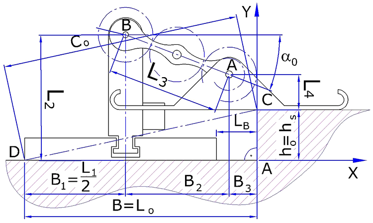
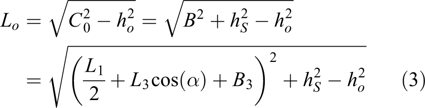
The two feet are making contact on the edge of the obstacle in point C and the round base in point D (Figure 3). Since the robot’s movements depend on its initial position relative to the obstacle, it is assumed that the distance LB between the round base and the obstacle at the initial moment of contact is known. From this and the known height ho of the obstacle, the distance B 3 is determined

Here, α 0 is the initial angle, at which it starts the contact for overcoming the obstacle.
The robot’s feet make contact with the obstacle along a line, which is projected in point C, but the circular base rests on only one point D, which suggests that the slip in C is less than in D. To simplify the model, it is assumed that C does not slip, that is, the feet are rotating about C and the point D is moving. This is convenient for the climbing process even though it is difficult to achieve. The goal is to get closer to this assumption with constructive design changes and using different materials. Then, it can be determined how the distance Lo between the feet and point D decreases when changing the angle α(t) rotation of the arm (Figure 4)
where

Stage 1 when overcoming an obstacle—attacking with the robot’s feet.
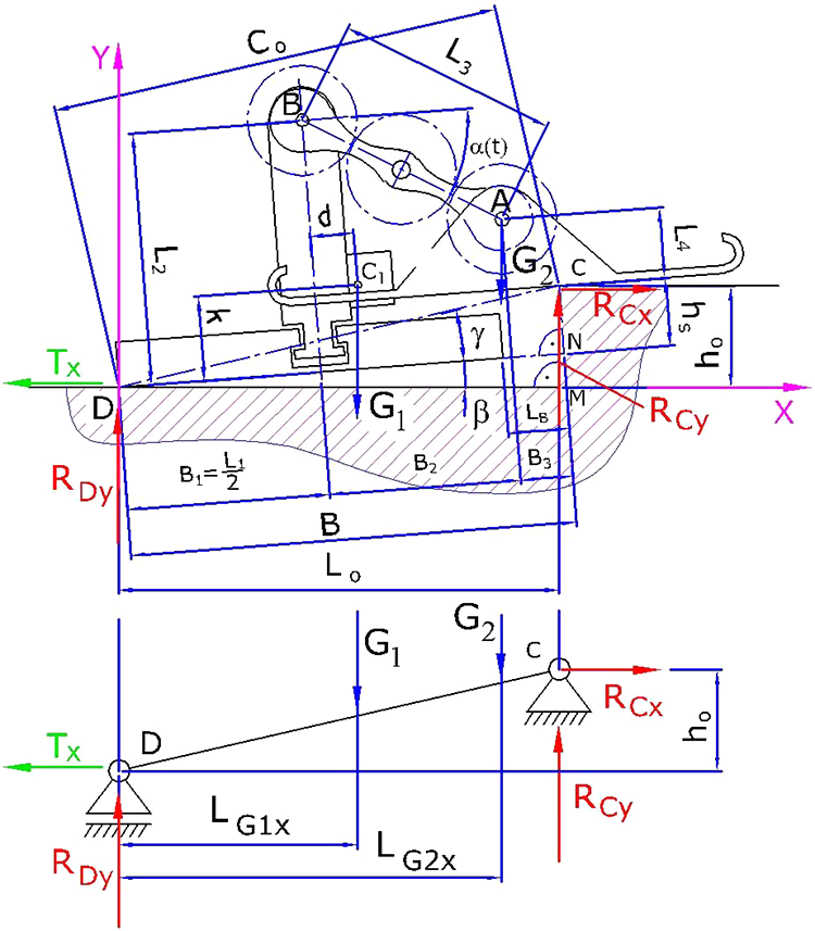
Angle β of the robot’s inclination with respect to the horizon is determined from (Figure 4)

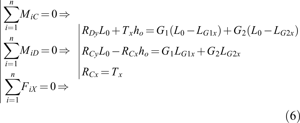
The static situation from this stage is considered. The influence of dynamic forces is neglected. The reaction forces are determined by the laws of statics
where

where
Stage 2: The feet come into contact in points C and D—the robot is standing on its feet
The climbing process continues as the feet rest on points C and D and move the body of the robot forward and upward (Figure 5(a)). The feet are stationary while the arms rotate around point A and the robot’s body moves forward. The angle of inclination β at this stage is determined by the height ho of the obstacle and the distance Lo . The relation between them is


(a) The feet contact in points C and D and (b) reaction force at point D at different angles and changing angle.
If the dynamic forces and slippage are not taken into account, the reaction forces in points D and C are

When the height of the obstacle ho
is small, the reaction forces remain positive. With increasing height ho
and angle of inclination β, it is possible for some of the reaction forces to change their sign. It is considered a case, where the height of the obstacle is ho
= 40 mm and the robot’s dimensions are provided according to Figure 2. Masses are m
1 = 245 g and m
2 = 30 g. During this stage,
Here, the weight G 1 moves along an arc close to the support C so that the reaction force RCy remains positive. The behavior of the reaction force RDy is of interest, from equation (9) and taking into account, the geometric dimensions of the robot it follows

where
Stage 3: The feet contact in point D and the body in point C
The next phase is when the robot’s body touches the obstacle in point C and the feet rest on the ground. The considerations for the movement, determination of the distance Lo , and the angle β are similar to those in stage 1. Reaction forces RCy and RDy remain positive. During this stage, the robot is stable but does not overcome the obstacle.
Stage 4: The body contacts in points C and D—stationary base
The base is stationary and rotated at an angle β, and the feet are moving. A relatively small mass m 2 is rotated but at a larger angle and at a greater distance from the supports C and D (Figure 6). The arm rotates around point B.

(a) The body contacts in points C and D and (b) reaction force at point C during the phase of stationary base at different angles and changing angle.
With such a great height, the obstacle cannot be overcome with a stationary body (Figure 6). In this case, however, it is possible that the robot loses stability and rolls over for which the value of the reaction force RCy is important

In Figure 6(b), the graph of the function (11) at a height of the obstacle ho = 40 mm and various inclinations of the robot is shown. It can be seen that as the angle of inclination β increases, the magnitude of the reaction force RCy decreases, and when β = 60°, there exist positions of the feet for which it becomes negative. The angle βr = 55.6° is critical. If the robot stands at this angle for any reason and tries to overcome an obstacle, it will lose its stability and rollover. If β < 55.6°, the robot remains stable and proceeds to stage 1.
Phase 5: Standing on the feet
This phase is crucial to climbing the obstacle. In this case, the robot is in the position of a stationary base or stationary feet, and as a result of a change in the center of gravity, the robot rotates around point C until it sits on the obstacle.
Stages 1 through 4 to overcome an obstacle are repeated until some of the following results are reached:
– Climbing the obstacle—phase 5 occurs—the circular base or part of it sits stable on the obstacle.
– The robot rolls over. With large values of the angle β, the robot may rotate in the opposite direction. In this case, the robot is on the ground and with appropriate control signals, it can “stand up” and stand in the correct position on the ground but cannot climb the obstacle.
– Multiple slippage of the feet and/or the base such that the robot cannot climb the obstacle.
Equation (10) is applied repeatedly for heights ho between 35 mm and 50 mm, each time looking for angle βo at which the obstacle can be overcome. The result is shown in Figure 7.

Change of angle when increasing height of the obstacle.
The critical angle βr = 55.6° determined from equation (11), at which the robot rolls over, because the reaction force RCy = 0, is shown with a blue horizontal line. It can be seen that when ho = 47.5 mm, the graph crosses the critical angle βr for which the robot rolls over. This means that a robot with such dimensions and mass layout cannot climb more than ho = 47.5 mm. In fact, this limit may be lower because dependencies (10) and (11) do not take into account the dynamics of the processes and slippage, and there are also random factors that make the robot difficult to position at a precisely defined angle β.
When moving on flat terrain, for the angles of rotation of the arms through the two phases,
Overcoming obstacles with a modified walking robot with a tail
Following the above considerations and conducting experiments with the 3D printed model, it is noted that the height of the overcome obstacle is limited due to the robot’s loss of stability. Adding an additional “tail” element on which the robot is supported could increase the height of the obstacle. It is mounted a paired tail {9} that is rigidly attached to the body {2} and does not rest on the circular base {1} (Figure 8). Increasing the length of the tail will also obviously increase the height of the obstacle that is overcome. This increases the overall size of the robot and its ability to change its orientation. The length of the tail Lt is selected so that there is no significant increase in the dimensions of the robot. For high obstacles, it turns out (from observation of the 3D printed model) that the robot with a tail passes only through two phases to climb an obstacle (Figure 9).

Walking robot with different tails attached.

(a) and (b) Stages when the robot overcomes high obstacle with a tail.
In the first stage, the feet are in contact with the obstacle at point C (Figure 9(a)). Initially, analogous to stage 1 without a tail, the base contacts at point D. Then, the tail reaches the terrain, and the feet are in contact at point C and the tail at point D from Figure 9(a). In this stage, the reaction forces RDy , RCy , and RCx are determined from equation (10) taking into account the geometric changes with the tail. During this phase, it is observed that the robot slips forward but the obstacle cannot be overcome. It reaches stage 2.
In the second stage with a tail, there is contact between the round base and the obstacle in point C and between the tail and the terrain in point D (Figure 9(b)). The arms are rotated and the feet move over the obstacle. Reaction forces are determined from equation (11) taking into account the new values for

In equation (12), it is accepted that Ht = 0 to simplify the expressions. Different cases are possible, when RDy < 0, overcoming the obstacle and RCy < 0, the robot rolls over. Graphs for the reaction forces RDy and RCy when ho = 40 mm, Lt = 45 mm, and the change of angle α are shown in Figure 10. The reaction force at point C becomes zero at β = 56°, which means that this is the critical angle when a tail is used. Figure 10(b) shows that a 40 mm obstacle is overcome with smaller angles of inclination. Obviously, the tail allows for overcoming higher obstacles. This model has the disadvantage of increasing the size of the robot and the length of the tail must be consistent with the particular application.

Reaction forces at points (a) C and (b) D when using a tail.
Experiments with the 3D printed prototype
Description of the experiment
The next stage of the study is to perform experiments with a real 3D printed model of the robot. The objective of the experiment is to search for appropriate shapes and materials for the feet and the base of the robot so as to climb an obstacle with maximum height while keeping the overall dimensions.
The prototype was created using a 3D printer with FDM technology from polylactic acid (PLA) material. Two GM22 gear motors with gear ratio 298:1 and a lithium-ion rechargeable battery with a nominal voltage of 4 V are used. The control is done via Bluetooth communication between the robot and a computer. The robot is controlled by an operator who, by means of specialized software, controls the two motors. The control software was developed in the LabVIEW (LabVIEW 2017 for Windows) environment (Figure 1). The software allows to manually adjust the speed of the motors, and the direction of movement of the robot being set by the keyboard or joystick. For this purpose, a dedicated and specially developed controller is used. The total mass of the robot is 275 ± 10 g, depending on the feet and the base used.
The experiment is conducted with the same robot, whose overall dimensions are shown in Figure 2. Only the shape and materials of the feet and the base are changed (Figure 11). Experiments are also made with the attachment of a tail (Figure 8). Different components of the robot are made up of two materials with different properties: biodegradable low-adhesion PLA plastic and a rubber-like FilaFlex material with better friction coefficient. To ensure comparability between the measurements, the basic geometric parameters of all the feet and bases are the same. Experiments were performed with a total of 48 combinations obtained from different variants of bases, feet, and tails, according to Figures 8 and 11. The variants for the base that use PLA material are denoted by B0—flat base and B1—jagged base. Feet made from PLA are labeled with L0—flat feet and L1—jagged feet. Bases with contact surface from FilaFlex are labeled B0f—flat and B1f—jagged. Feet made from this material are denoted by L0f—flat surface and L1f—jagged surface. Tails are denoted for the PLA and FilaFlex material, respectively, with T0 and T0f. In Table 1, all the combinations without a tail are given. The rest of the combinations are obtained by adding T0 or T0f, for a tail with a FilaFlex pad, at the end of the abbreviations. Some examples for the used abbreviations: B0f L1 denotes a robot, whose base has a FilaFlex pad and the feet are jagged and made of PLA (Table 1, row 3, column 2), and B1 L0f T0 denotes a robot with a jagged base, flat feet with FilaFlex pads, and a tail from PLA.

Shapes and dimensions of the feet and the base of the robot.
Abbreviations for the used feet, bases, and materials.

The experiments are conducted with the same speed of the motors. The obstacle is a cardboard model with a vertical and a horizontal section. The experimental setup includes raising the obstacle height by 1 mm until reaching a threshold, where the obstacle cannot be overcome. An operator directs the robot to attack the obstacle frontally. When the base is raised, the operator adjusts the orientation so that the jagged edges of the base are parallel to the edges of the obstacle for better traction. Before starting each experiment, the robot is positioned at a distance of 5 mm from the obstacle and placed in the same starting position. The obstacle is considered overcome by a minimum of three successful attempts out of five.
Results from the experiment
Experiments were conducted with a walking robot (Figure 12) to determine the efficiency when overcoming an obstacle depending on the physical properties and the shape of the two materials PLA and FilaFlex.

Phases of climbing an obstacle with the 3D printed model.
In Figure 13, a comparison between different combinations of bases and feet made of PLA without a tail (in blue) and with a tail (in red) compared to a control configuration is presented. For the control configuration, B0 L0 (flat feet and flat base), which corresponds to the lowest overcome height of 19 mm–100%, is taken. This control serves to investigate the effect of changing the shape and type of the material on the height to be overcome by the robot.

Influence of the shape, when using only PLA material, when overcoming an obstacle with height—ho (mm).
Experiments are carried out to determine the trajectories of characteristic points from the robot’s links during its movement. A 3D printed model of the robot is used. Points A and B from the robot arm {3} are highlighted in a contrasting color to distinguish them from the other elements. The camera is stationary and is positioned perpendicular to the movement of the robot (Figure 9).
The best result of a 200% increase, corresponding to 38 mm without a tail, is obtained with a combination of jagged base and jagged feet—B1 L1. These indentations keep the robot in a good position for overcoming the obstacle. The same combination, but with an added tail, resulted in an increase from the control of 231.6% (44 mm). It can be seen from the figure that the lowest increase in the overcome height is present in all combinations with flat feet. This is due to the significant sliding of the robot along the edge of the obstacle, returning it back during every attempt to surmount it.
In Figure 14, the control is compared to different combinations of feet and bases from FilaFlex with and without a tail with FilaFlex as well.

Influence of the shape, when using FilaFlex material when overcoming an obstacle with height—ho (mm).
The best result of 200% without a tail is obtained with a combination of flat base—B0f with flat feet—L0f. The same combination with the addition of a tail resulted in the most significant increase of 268.4%, corresponding to 51 mm of the overcome height. The reason is most likely due to the good grip with the edge of the obstacle due to the properties of the FilaFlex material. In this case, the jagged shape of the feet and the base does not contribute to a significant improvement in the overcome height relative to the control. Here, combinations of several factors can be highlighted. The joint impact of all FilaFlex surfaces limits the robot slippage. The jagged surface grasps the edge of the obstacle. The good adhesion of the FilaFlex material to the contact surface creates additional friction, which limits the adaptive sliding of the robot. The most unfavorable angle of inclination and, respectively, rollover is observed with the combination of jagged feet and jagged base.
In Figure 15, the effect of different combinations of feet and bases from PLA and FilaFlex without tails relative to the control is shown.

Influence of the materials PLA and FilaFlex, without a tail, when overcoming an obstacle with height—ho (mm).
The largest increase of 226.3%, corresponding to 43 mm, is achieved with the combination B0f L1 (flat FilaFlex base and jagged PLA feet). The most unfavorable combinations are obtained with flat feet from PLA.
In Figure 16, different combinations of PLA and FilaFlex bases and feet with a tail from PLA are shown.

Different combinations of PLA and FilaFlex with a tail when overcoming an obstacle with height—ho (mm).
Here, again, the most unfavorable combinations are obtained with flat feet from PLA. In these cases, the tail improves the result to a small extent. The best result of 273.7%, corresponding to 52 mm, was observed with the combinations B1f L0f T0 and B1 L0f T0 with flat feet from FilaFlex.
In Figure 17, different combinations of feet and bases from PLA and FilaFlex when using a tail with a FilaFlex pad are shown.

Different combinations of components from PLA and FilaFlex, tail with FilaFlex pad and overcome obstacle with height—ho (mm).
The best result of 242.1%, corresponding to 46 mm, was observed in the combinations B0f L1 T0f and B0 L1f T0f. These two combinations lead to a better result than using combinations with PLA material only.
In Figure 18, the values of the index Kro , which are calculated according to equation (1), are shown. The index determines the effective height of the overcome obstacle depending on the length and height of the robot. The values of the index are calculated for all 48 cases and are presented in Table 2.

Values of the index Kro for PLA and FilaFlex materials and combinations of both.
Values of the Kro index for all 48 configurations of the robot “Big Foot.”

In Table 2 the maximum index values for PLA, FilaFlex, and combinations of both PLA and FilaFlex materials for experiments without adding a tail are colored in blue. The maximum index values for the corresponding materials when a tail is added to the robot are colored in red.
For better visualization, in Figure 18, only the reference values for B0 L0 and B0 L0 T0 and the seven highest values for the Kro index are shown. From the figure, it can be seen that the lowest values of the index are obtained for the combinations B0 L0 and B0 L0 T0 with values 0.17 and 0.16, respectively. The highest value of 0.39 from the combinations without a tail is for B0f L1, and for the combinations with a tail, the highest value of 0.41 is for B1f L0f T0 and B1 L0f T0.
Experiments to overcome an obstacle with a maximum height are made with various mobile robots. Based on literary sources, 25 –28 their respective K indexes are defined and given in Table 3. In yellow is marked the robot Big Foot, discussed in this work.
K index of different mobile robots.

The K index is determined for a humanoid robot NAO 27 and nonhumanoid mobile robots, 25,26,28 where it has the highest value of 0.5 for a robot with a hybrid mechanism. 28 For a robot using a transformation mechanism with a rotation of its feet K = 0.45, 25 hybrid robots take advantage of the wheeled and walking robots. In another study, 26 a hybrid mechanism is also used, but the index has a lower value of approximately 0.2. The robot proposed in the present study has higher K index values than a humanoid robot NAO 27 and nonhumanoid mobile robot. 26 Compared to all considered robots, Big Foot overcomes high obstacles using only one of its two motors.
From the conducted experiments, the following conclusions can be made: The best results in the experiments are obtained with B1f L0f T0 and B1L0fT0 in which FilaFlex flat feet are used. The lowest overcome heights are obtained in all combinations with flat PLA feet. Changing the shape from flat to jagged (Figure 11) results in a significant increase of the overcome height, in some combinations over two times with respect to the control. The FilaFlex material has good adhesion and the change in shape from flat to jagged, according to Figure 11, makes it difficult to overcome the obstacle due to the additional friction. For the PLA material, the change in shape from flat to jagged significantly improves the results. The use of a tail in the combinations with jagged base and feet also contributes to improving the result by decreasing the angle of inclination. Combining components made from FilaFlex and PLA leads to a reduction in their drawbacks when used separately. The use of both types of tails, from PLA and FilaFlex, predominantly results in improved climbing results.
Conclusions and future work
The main stages of movement when overcoming obstacles are presented. The maximum height the robot can overcome is theoretically determined. Experiments are conducted with a 3D printed robot to determine the influence of the shape and materials of the feet and the base for overcoming high obstacles. A maximum obstacle height of 43 mm is determined, without a tail, which is closer to the theoretically determined value ho = 47.5 mm. The maximum height that overcomes the tail-sized robot according to Figure 8 is determined. A dimensionless index Kro is used to compare a robot with the height of the obstacle ho , which it overcomes. A comparison is made with other similar robots, for which the dimensions and the overcome heights are known. The results confirm the theoretical layout and the good mobile qualities of the proposed construction based on a minimalist approach. From Table 2 and Figure 18, the percentage improvement of the Kro index with respect to the reference values for flat surfaces of the base and feet of the robot with and without tail, B0 L0 and B0 L0 T0, respectively, is calculated. The maximum improvement of the K index for the robot without tail is 229% and for a robot with tail is 256%.
Future works should plan experiments involving different slopes, steps, and combinations of various complex obstacles and staircases. Experiments are also planned to move the robot on surfaces with different properties, such as sand, soft soil, and others. It is assumed that the robot would be suitable for movement on such type of surfaces because its feet and base have large areas.
The study should expand to overcome more complex obstacles, such as stairways with an angle of slope typical for residential buildings.
Experiments should be planned with different material densities for different components of the robot to improve the robot’s adaptability to the obstacle and to reduce the impact loads. Development of feet, bases, and tails with better possibility for passive adaptation to the obstacle is also considered.
An appropriate control strategy will be investigated to reduce the loads during climbing and descending. Improvements in the sensor and control system will be explored as well as new applications of the robot, including education.
Footnotes
Declaration of conflicting interests
The author(s) declared no potential conflicts of interest with respect to the research, authorship, and/or publication of this article.
Funding
The author(s) disclosed receipt of the following financial support for the research, authorship, and/or publication of this article: This work was supported by the National Scientific Research Fund, project no. NIH17/10—December 12, 2017.