
Abstract
Rehabilitative robotics is an area in the medical field, where one can see a variety of different robotic applications, one of which is the use of robotic exoskeleton in rehabilitation of paraplegics. Current developments are only able to support paraplegics at most and require manual operation of crutches by the patient. In order to overcome this limitation, a theoretical model of a robotic device with actuated robotic crutches is proposed, which can be used to support people with high-level disability, such as quadriplegics who cannot use the existing solutions to perform walking gaits. This work presents kinematic trajectory planning of the proposed model and dynamic analysis of main movement stages. Finally, we present an open-loop control scheme that uses time scaling in order to track the desired joint trajectory of the under-actuated motion stage of crutch swinging. A simulated robotic model has also been developed using Simulink [version R2012b to R2014a]/SimMechanics ([version first generation] developed by Mathworks inc.) environment and has been used for verifying dynamic computations and simulating the robotic device movement under the open-loop control commands of joint torques.
Keywords
Introduction
Rehabilitative robotics is a continuously developing area of research. In this area, most robotic assisting devices are classified into three major applications: Using smart prostheses on amputees or instead of severely damaged limbs in order to overcome mobility limitations, as shown by Burck et al. and Au et al.
1,2
Reestablish limb’s functionality on people who experienced trauma that damaged the limb’s functionality, but the motor function still exists and can be recovered (such as stroke). In this case, it appears that a lot of attempts to recover the limb’s functionality are done using robotic assisting devices, such as the ones shown in the studies by Kahn et al.,
3
Sale et al.,
4
Bernhardt et al.,
5
Ollinger et al.,
6
Ferris et al.,
7
Fan and Yin,
8
and Ferris and Lewis.
9
Replacing limb’s motor function in cases where it is damaged permanently, but the limb itself is intact (such as paraplegia). A solution to this problem is often the use of wheelchair,
10
but this solution leads to a variety of problems ranging from decrease in bone and muscle density to problems in cardiac and urinary systems. Another problem is the formation of bedsores, in addition to deterioration in the patient’s mental state. Another possible solution, which helps avoiding the mentioned problems, is the use of external exoskeleton.
Robotic exoskeletons are used in many fields ranging from military and industrial to entertainment and medical uses. In the military field, it is used for enhancing combat soldier’s ability to traverse rough terrains while lifting heavy objects, whereas in the industrial field, exoskeletons are used to support workers while carrying a heavy load. 11 One field, which is continuously developing, is the use of exoskeleton for rehabilitation, where it is used to support people suffering from disabilities while performing gait. HAL, Cyberdyne’s (Tsukuba, Japan) device is an example for using exoskeletons to support and expand the physical capabilities of users, capable of moving by themselves. 11 Rewalk’s, Ekso’s, and also HAL’s exoskeletons are able to support patients suffering from paraplegia while performing gait. 10 –16 These solutions, however, require upper-limb and lower-limb coordination, achieved by the patient’s ability to support himself using crutches during the gait, thus causing the solution to be effective only for several disabilities. For higher levels of disability, where the hand function is severely limited, we propose to add active robotic crutches. These crutches are essential for adding support and stabilization in order to maintain upright position of the patient, which is a major difficulty in upright walking of disabled patients. Thus, the primary goal of this article is to conduct a feasibility research on a theoretical planar model of an exoskeleton with an active robotic crutch, which is shown in Figure 1. Feasibility check of the robotic device includes design of kinematic trajectories, built based on field experiments with existing exoskeletons combined with the research developed on bipedal walking robots. 10 –13,17,18 These trajectories are fed back into the dynamic equations of motion and used for computing joint actuation torques and ground reaction forces, which are used to assure non-slipping contact while performing gait. The computed control torques are applied at the robot’s joints in open-loop control. A secondary objective of our research is the development of a simulation tool, based on Simulink/SimMechanics environment, 19 which can be used as a verification tool for various numeric computations. As shown in Figure 1, the robotic device includes an actuated crutch, which is used together with the robotic legs for support and maintaining gait, thus enabling usability for people suffering from wide range of disabilities, including quadriplegics.
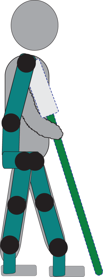
Robotic device carrying a patient.
While the dynamics of walking with manually operated crutches has been analyzed in previous works, 20 –22 the proposed concept of robotic exoskeleton with active crutches still requires theoretical feasibility investigation. A work, which is closer in spirit, is the augmented robotic limbs, 23 which are mainly used for upright stabilization and load reduction for healthy persons carrying heavy loads.
A key factor in our analysis is the fact that the motion stage of crutch swinging is under-actuated, that is, the number of actuation input is less than the number of degrees of freedom (DoFs), which poses limitation on feasible dynamic motions. While set-point stabilization of equilibrium postures of under-actuated systems is well-studied, 24 the problem of tracking a desired trajectory is mainly solved using control methods such as backstepping and feedback linearization, which are applicable for systems with very specific structure. 25,26 In this work, we use the method of time scaling 27,28 for obtaining open-loop inputs of actuation torques for tracking a desired kinematic path. This method is suitable for under-actuated systems and has been applied in previous works for multi-contact robotic manipulation, 29 as well as biped robot control. 30
The article is organized as follows. First, formulation of the general robotic model and decomposition of robots gait into three movement stages are presented. Kinematic trajectory planning of the robot’s gait is also shown next, thus followed by dynamic analysis of the main movement stages. A proposed open-loop control method for under-actuated sub-mechanism tracking is then shown, along with robot’s simulation, developed in SimMechanics environment for verifying direct computation results. Finally, the concluding section discusses the limitations of the results and lists some possible future extensions of the research.
Theoretical model
In this section, we present a simplified planar model of the robotic structure and classify the robot’s different stages of movement. Links’ lengths and mass notations are shown in Figure 2(a) and values are shown in Table 1. Each link is considered as a rod with uniform mass, having moment of inertia

(a). Gait parameters and (b). Degree of freedom (DoF) notation.
Links’ length and mass values.

The robot’s DoFs are shown in Figure 2(b). Each joint represents 1-DoF. All joints are revolute except d6, which is prismatic. Joints description is shown in Table 2. The robotic device, shown in Figure 2(b), has 9-DoF represented by the vector of generalized coordinates

Joint’s type.

The roles of all joints and their actuation type (active/passive) in our proposed exoskeleton model are shown in Table 2. As shown in Table 2, some joints are actuated, while others are passive. One can see a particular interest in the type of ankle joints θ1l and θ1r, which varies depending on the state of foot contact, as detailed in the following assumption
Assumption 1
If the foot is not in contact with the ground during the movement stage—the ankle joint is considered as active. Otherwise, the joint is considered as passive.This assumption is based on the fact the foot’s mass is negligible compared to other links. Thus, a relatively weak torque is required at the ankle joint during foot swinging. (Practically, in exoskeleton devices used by paraplegics, the ankle joint contains a semi-passive spring-based mechanism with a limit stopper. 31,32 This complication is not considered here, see further discussion in the concluding section.) On the other hand, when the foot is in contact with the ground, it forms a closed kinematic chain whose effective inertia is much larger and requires larger torques. Therefore, the torque of a weak elastic mechanism at the ankle joint becomes negligible and the joint is considered as being passively affected by the closed-chain kinematic constraints. This assumption results in simplifying the kinematic analysis and enabling the determination of the number of DoFs and actuation type in each stage of movement, as detailed next.
Stages of movement
The robot’s motion can be divided into three movement stages: Movement stage 1: Moving the rear foot (swing foot) forward from toe off to heel strike, as shown in Figure 3. Movement stage 2: Moving the crutch forward while maintaining the same legs’ position as was in the previous movement stage, as shown in Figure 4. Movement stage 3: Front foot rotation from heel strike to full contact with the ground, followed by rear foot rotation from full contact with the ground to toe off, as shown in Figure 5.

Movement stage 1.

Movement stage 2.

Movement stage 3.
Partition into these movement stages is determined by transitions in the feet and crutch’s contact states. It is also based on previous works on motion analysis for crutch-assisted rehabilitative exoskeleton, 12,20 as well as healthy human gaits, 17,18 and bipedal robots. 33 Simulation movies of the robot’s different motion stages are included in the online supplementary material. In order to plan robot’s gait, one must determine the number of mechanism’s DoF at each motion stage, which depend on the contact state and kinematic constraints. This can be determined using Grübler’s equation 34

where m is the mechanism’s number of DoFs also known as mobility, d classifies the problem to spatial or planar, and fi represents the number of DoFs in each joint. Our model is planar so d = 3 and fi = 1. n is the number of links and p is the number of joints in the mechanism. We use equation (2) to obtain the DoF in each movement stage and compare to the number of active joints (e.g. actuators). Based on the comparison, each movement stage is then classified as either under-actuated or fully actuated.
Movement stage 1
Using Grübler’s equation (2) on the mechanism shown in Figure 3, moving the robotic structure requires seven actuated DoFs (
Movement stage 2
Using Grübler’s equation (2), seven DoFs are required to move the mechanism shown in Figure 4 (
Movement stage 3
Using Grübler’s equation (2) on the mechanism shown in Figure 5, moving the robotic structure requires six actuated DoFs (n = 11, p = 12, and fi = 1), so at least 6-DoF must have servos in order to move the mechanism to the required position. As one can see from Table 2, and following assumption 1, both ankle joints (θ1l and θ1r) are passive and the theoretical model has six actuated DoFs. Thus, movement stage 3 is considered fully actuated.
As shown in Figure 5, robot’s movement in stage 3 is simpler than stages 1 and 2. Movement in stage 1 is based dynamically on the existence of no-slip and contact constraints as mentioned earlier, and stage 2 is an under-actuated movement stage. Based on these reasons, this article is focused on the analysis of movement stages 1 and 2 only.
Kinematic trajectory planning
This section describes kinematic motion planning used to move the robot along desired trajectories, dictated by the movement stages. For convenience of the analysis, the chosen kinematic trajectories are composed of basic motion primitives that are based on observations from human walking gaits.
Movement stage 1
This stage focuses on moving the swing foot forward. Kinematic trajectories, used to determine robot’s path by inverse kinematics, are defined by motion of the swing foot’s endpoint (
Foot trajectory planning
As shown in Figure 2(a), foot trajectory is represented by

where i = 1,2 represents the interval number and yi is the value of

where
In order to compute

where

These constants can then be used to compute

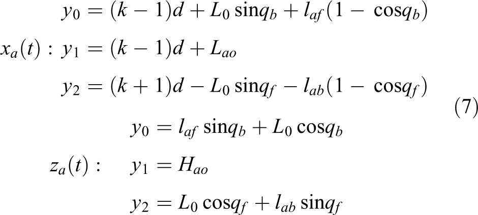
All the parameters used for building the trajectory are mentioned and explained in Table 3. The same computation technique is applied for obtaining the ankle’s x and z-coordinates. Constraints for ankle’s coordinates, using the same t values as before, are shown in the following expressions
Gait planning parameters.
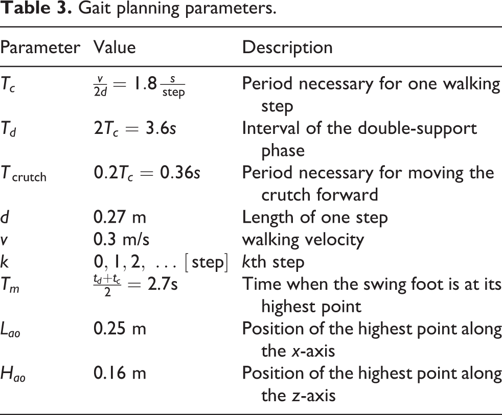
The reader can refer to Table 3 for explanation about the equation parameters.
Pelvis and lower back trajectory planning
During the walking cycle, the pelvis moves to balance patient’s body. Robot’s pelvis motion was based on an arched trajectory, followed by stance leg with locked knee acting as an inverted pendulum. 13,36 –38 θ4 trajectory was planned using the third-order polynomial, based on the following initial and final values
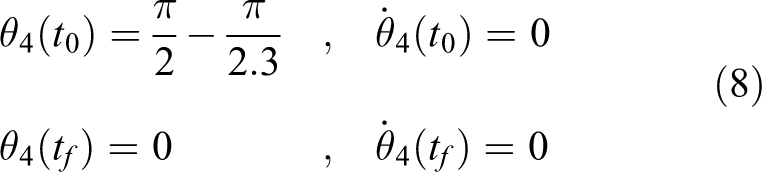
where t0 and tf are the initial and final times of the motion stage, respectively. Stance leg angle θsa acts as opposite to lower back angle θ4, in the same angle’s range, according to relation

while

The value in equation (9) is also taken from the works of Esquenazi et al., 10,12 Mikolajewska and Mikolajewski, 11 and Cass. 13 Pelvis and lower back movement is determined, using the fact that L2 and L1 are constant, on the following relations
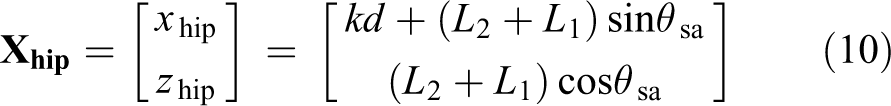
Crutch’s endpoint is fixed during the movement.
Movement stage 2
This stage focuses on moving the crutch forward. Robot’s legs are fixed and form a closed kinematic chain (rigid link acting as parallel sub-mechanism), thus joint values θ2l, θ3l, θ2r, and θ3r are fixed to their final orientation given at the end of the previous stage. Crutch’s movement is determined using

Crutch’s end effector was planned using the third-order spline according to the constraints, which are given by

This concludes the kinematic trajectory planning for motion stages 1 and 2.
We now study the dynamics at movement stages 1 and 2 and compute the required actuation torques. While the motion of each movement stage is dynamic, we impose that the transitions between stages are reached at complete stop. This assumption is common in crutch-assisted motion and appears also in previous work. 12 Thus, we do not consider here the effect of impacts at ground touchdown of feet or crutch, which has been studied by Carpentier et al. 39 and Font-Llagunes et al. 40
Dynamic analysis of movement stage 1
In this stage, the robot swings the rear leg forward while being supported by a crutch, placed on the ground with full sticking contact. The robot’s equations of motion are formulated using constrained Lagrange equations 34 as

where
The holonomic constraints represent the fact that the endpoint of the crutch is fixed. We express the vector of crutch’s endpoint using generalized coordinates

Then, the constraint can be expressed as
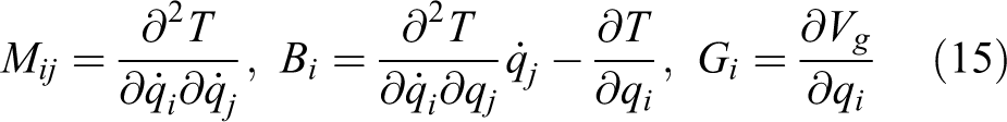
where T is the robot’s kinetic energy, computed using the following

where

where Mj is joint/link j mass, and Vg is the robot’s potential energy, computed using the following

where
The two holonomic constraints (no-slip and contact) remove 2-DoF from the 9-DoF, shown in the motion equations (equation (13)). The robotic structure has two unactuated and passive joints

where

Equation (19) can be rearranged as
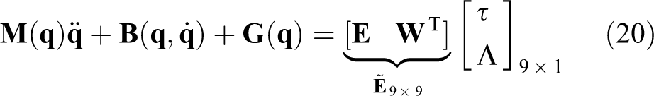
The matrix

By substituting the desired position, velocity, and acceleration vectors (

SimMechanics model of movement stages 1 (a) and 2(b). (a) is the left side and (b) the right side.
Source files and animation movies of the SimMechanics model’s motion are included in the online supplementary material. The SimMechanics environment provides an independent simulation of the robot’s dynamics, which is not based on our equations of motion. From the plots in Figure 7, the perfect matching between the results of the SimMechanics model and numerical integration of our equations of motion provides a strong indication for the correctness of our theoretical analysis.

Actuation torques/forces during movement stage 1.
As shown in Figure 3, during movement stage 1, the robot is being supported by two contact points—crutch and stance foot. In order to ensure no-slip at both contact points, one must compute reaction forces occurring from crutch and foot interaction with the ground. While reaction forces in crutch’s tip, obtained from the simulation tool, were compared to those computed using direct computation of Λ(t), in stance foot interaction, reaction forces were obtained only from the simulation tool. Resulting normal contact forces in crutch’s tip and stance foot are shown in Figure 8, while SimMechanics model of stage 1 is shown in Figure 6(a).

Normal contact force at (a) crutch’s tip and (b) stance foot.
As seen in Figure 8(a), contact force in normal direction is positive (
By computing the ratio between two constraint forces (tangential and normal), one can obtain critical friction coefficients, both for crutch’s tip and stance foot, which are shown in Figure 9. As shown in Figure 9, applying a friction coefficient greater than μ = 0.2878 for crutch’s tip and a friction coefficient greater than μ = 0.1197 for stance foot will result in no-slip for both contacts during movement stage 1. These two values are physically achievable in practice.

Ratio of tangential-to-normal contact force at (a) crutch’s tip and (b) stance foot.
Under-actuated dynamics and control for movement stage 2
In this stage, the robot swings the crutch forward in order to advance and prepare for the next step in the walking cycle, while maintaining the same legs position as was in the end of the previous movement stage. Given the rigid chain created by the robot’s legs (while all joint angles are kept constant), the full dynamic model could be reduced to 3-DoF, shown in Figure 10. Using equation (13) with

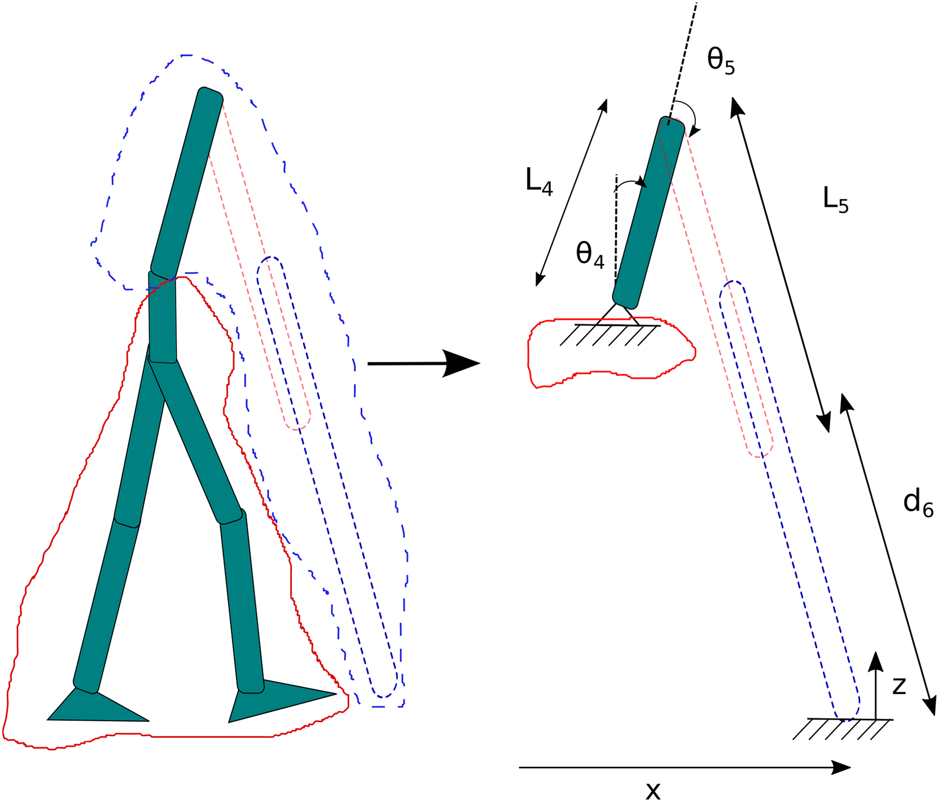
Simplified model.
One obtains three motion equations with only two actuated DoFs
First, one should check if the crutch can track the desired motion trajectory described earlier, while using only two actuated joints
Under-actuated reference trajectory tracking during crutch swing phase
We define geometric parameterization of joints’ trajectory

The system must satisfy the following motion equations

Defining equation (24) to be s-dependent through the following relations
we obtain
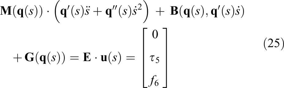
while

The first row of equation (25) contains the requirement that the torque at the passive hip joint is identically zero. Left-multiplication of equation (25) by

where A, B, and C are s-dependent terms (which will not be shown here for brevity). Equation (27) is a second-order nonlinear scalar differential equation whose coefficients are s-dependent. A solution for the time scaling s(t) is obtained by numerical integration with events (ode45+event function) following the state-space representation

while: Initial condition
Actuation torques/forces vector
Using the s(t) time scaling obtained from the solution of equation (27), the following results are obtained. Using open-loop control, based on the state-space representation shown in the following
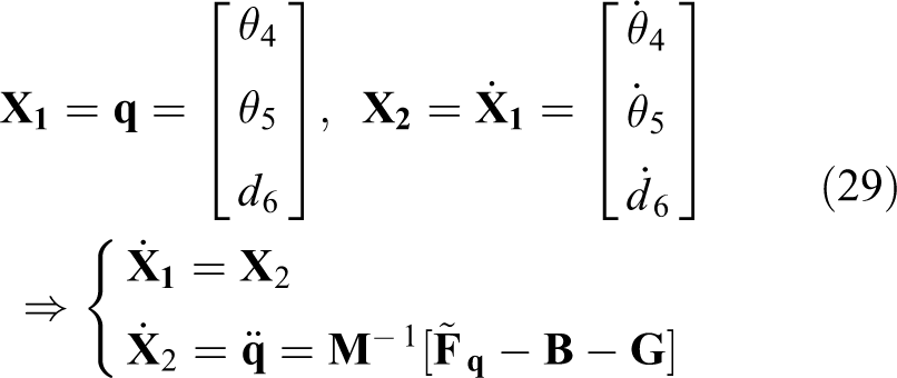
Joint’s actuation torques and forces were fed as an input to model’s actuators (τ5 and f6), resulting in throwing the crutch forward. Robot’s motion was simulated and verified using SimMechanics simulation, under the same open-loop control (forward dynamics method). Crutch’s tip trajectory, obtained from SimMechanics, was compared to desired trajectory and the trajectory obtained from direct computation. The results are shown in Figure 11. The successful tracking of the desired trajectory with under-actuated control proves the correctness of our time-scaling method. Agreement between numerical integration results and the SimMechanics model again verifies the correctness of our equations of motion.
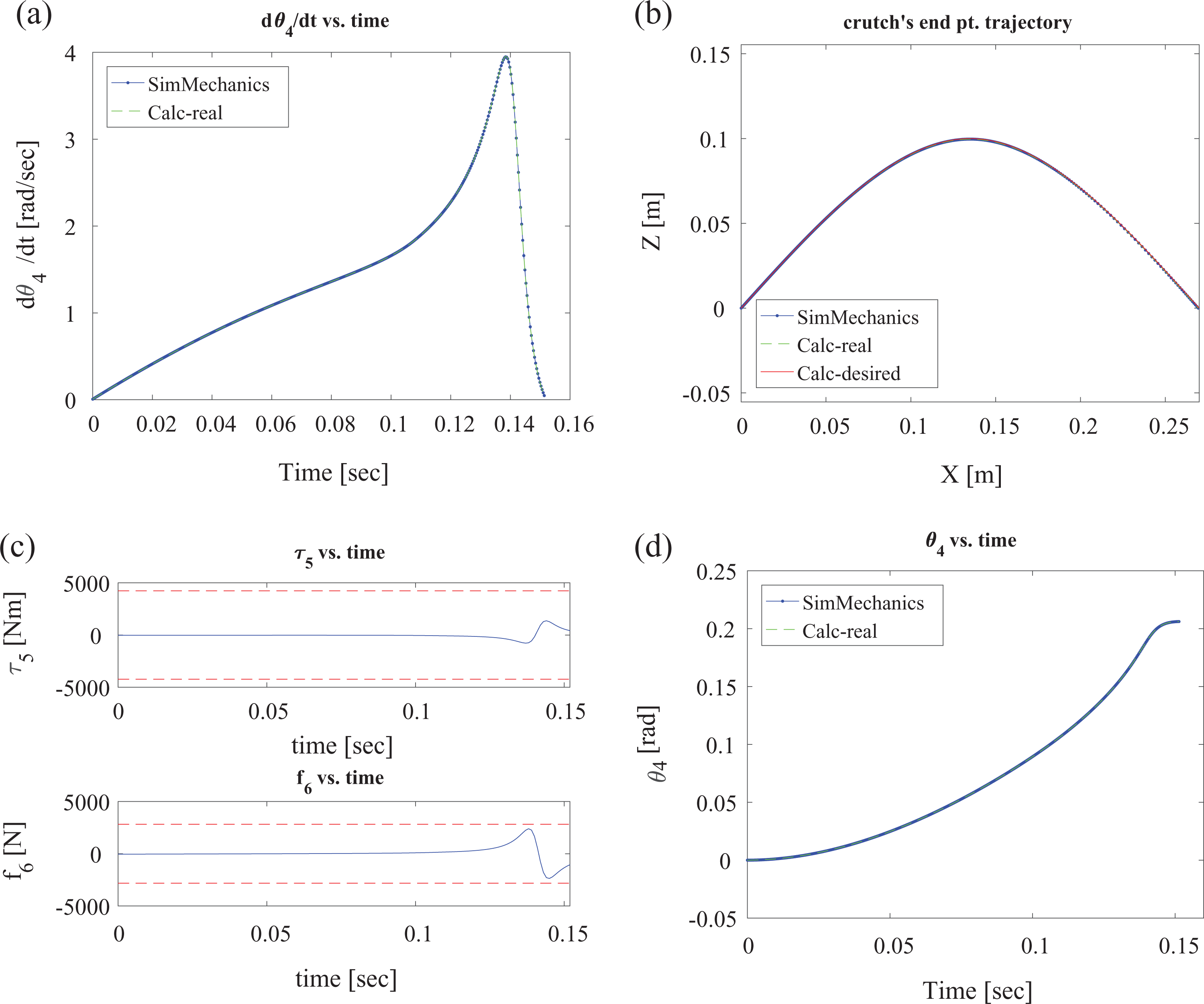
(a) s-method simulation results (ds/dt vs. time), (b) crutch tip tracking, (c) actuation torques/forces, and (d) lower back angle versus time.
Figure 11(c) shows that crutch’s actuation torques, obtained using the time-scaling method, are within actuation bound limits which were defined. One can also see that joint actuation torques for movement stage 1, shown in Figure 7, are also within these bounds. Because of the actuation torques magnitude in movement stage 1 (less than 1% of the smallest actuation torque bound), practical bounds are not shown in Figure 7. The difference in actuation torques magnitude is due to movement nature: In stage 1, movement nature is quasi-static and reaction forces carry most of the robot’s weight, and in stage 2, movement nature is dynamic, swinging the crutch creates a movement of trying to swing an inverted pendulum and thus the required torques are smaller.
Switch from full contact to flight phase in t = t0
After succeeding in tracking the crutch’s desired trajectory under the shown constraints, mentioned previously, evaluation of the equations used for contact separation in t = t0 is shown. These equations were used to create the permissible region of initial actuation force and torque. This region guarantees contact separation while applying zero torque to lower back joint (θ4), which is passive. Two possible cases should be considered while switching from contact to flight phase: 1. Crutch is in sticking contact—contact + no-slip constraints. Using the motion equation (13) while maintaining no-slip contact results in constraint forces shown in the following

For further explanation, one can refer to the study by Murray et al.
34
Note that the matrix
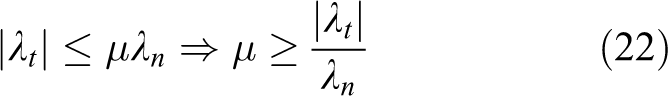
2. Crutch is in slipping contact—contact constraints while slipping occurs. Using Coulomb’s friction law

In order to guarantee detachment at t = t0, one has to require that both contact modes are infeasible, that is, λn ≤ 0. By evaluating equations (30) and (31) in t = t0 (

In Figure 12, we show the region created by intersection of the two inequality constraints (equation (32)) obtained for the two contact modes. One can also see the point that represents actuation torques/forces using the time-scaling method in t = t0 is marked by “*”. Figure 12 shows that the point is within the permissible region, thus contact separation at the beginning of this motion stage is guaranteed.

Permissible actuation torques/forces region.
Summary
In this article, we performed a feasibility check on a simple planar model of a newly proposed robotic exoskeleton with active crutches. As part of the feasibility check, we numerically investigated the robot’s dynamics while trying to track our planned kinematic trajectories and formulated open-loop control inputs actuation forces and torques at the joints. We have found that for one of the major movements stages, the model’s movement can be achieved using sticking contact constraint forces. In the second major movement stage, we proposed an open-loop control scheme, designed for tracking of an under-actuated system. Our formulated open-loop control inputs of actuation forces and torques at the joints, based on time variation of joint’s trajectory geometric parameterization, achieved contact separation in the first moment and tracking of the planned kinematic trajectory. Thus, feasibility of implementing the gait’s major movement stages has been theoretically proven.
Discussion
We now briefly discuss the main limitations of our model and present several directions for future extensions of the research. First, our kinematic model of the robot is simplified. In particular, it does not account for details of the foot contact and ankle joint. Typical designs of ankle joint in lower-limb exoskeletons consist of a semi-passive dorsiflexion mechanism 31,32 with a torsion spring and mechanical stoppers. Our model does not account for details of such a mechanism and uses instead the simplification of assumption 1, which states that the ankle joint is active at some motion stages and passive at others. In addition, it is assumed that the front foot is in heel contact during motion stage 2 of crutch swing, which is not fully realistic in healthy human gaits. These assumptions have been made in order to simplify the kinematic analysis of actuated DoF, without requiring a combination of both kinematic and dynamic considerations. Development of more detailed kinematic and dynamic models of the ankle and foot mechanics is a key challenge, which is essential for future realization of our proposed robotic exoskeleton. In addition, future generalizations should consider theoretical analysis of the proposed assistive device operated in transient motion of sitting and standing, which are highly essential tasks for disabled patients in everyday life.
Second, our kinematic model is limited to planar motion. The proposed kinematic trajectories are also simplified and are not fully based on human motion. We are currently working on the extension of the analysis in order to account for kinematic trajectories, which are adapted from measurement data of human motion collected during walking gaits. 41 Nevertheless, reliable projection of the measured data onto low-dimensional models is itself a challenging task. 33 Additionally, our model considered a prismatic actuator for the crutch for simplicity of the analysis, and more general configurations of active crutches should be investigated. Finally, our analysis of the robot’s dynamics does not account for interaction between the human and the exoskeleton due to possible kinematic discrepancies and antagonistic efforts. Moreover, we provide only open-loop control of the actuation torques that are required in order to generate the desired kinematic trajectories. Augmenting our work with feedback control for stabilization of trajectory tracking is essential for any practical implementation and for improving the robustness under external perturbations and unmodeled effects. In lower-limb exoskeletons for paraplegics, 14,16 an essential aspect is reactive control, which adapts to forces applied by the human and possibly regulates force-related quantities such as foot-ground center of pressure. 42 In the case of severely limited patients such as quadriplegics, the role of reactive feedback is still an open unknown issue. In summary, all differences abovementioned between the current simple theoretical model and real behavior of a rehabilitative device in practice should be resolved in future works by conducting clinical trials with disabled subjects in physical experiments.
Supplemental material
supplamental_material - Modeling the dynamics and control of rehabilitative exoskeleton with robotic crutches
supplamental_material for Modeling the dynamics and control of rehabilitative exoskeleton with robotic crutches by Adi Cohen and Yizhar Or in International Journal of Advanced Robotic Systems
Footnotes
Author note
The content of supplemenary material is: video movie files and Matlab and Sim Mechanics code files.
Declaration of conflicting interests
The author(s) declared no potential conflicts of interest with respect to the research, authorship, and/or publication of this article.
Funding
The author(s) disclosed receipt of the following financial support for the research, authorship, and/or publication of this article: This work was supported by the Technion Autonomous Systems Program under award no. 2015136.
Supplemental material
Supplementary material for this article is available online.
References
Supplementary Material
Please find the following supplemental material available below.
For Open Access articles published under a Creative Commons License, all supplemental material carries the same license as the article it is associated with.
For non-Open Access articles published, all supplemental material carries a non-exclusive license, and permission requests for re-use of supplemental material or any part of supplemental material shall be sent directly to the copyright owner as specified in the copyright notice associated with the article.