
Abstract
A combination of Internet of Things and multiple robots with sensors has been an attractive research topic over the past years. This article proposes an Internet of Robotic Things system structure to monitor events, fuse sensor data, use local robots to determine a best action, and then act to control multiple mobile robots. The Internet of Robotic Things system includes two main layers: the host controller layer and the multiple robots layer. The controller layer communicates with the multiple robots layer by Wi-Fi module. The Internet of Robotic Things system helps finish five tasks: localizing robots, planning paths, avoiding obstacles, moving to waypoint stable, and creating a map. Based on depth data from depth camera and robot posture, a mapping algorithm is proposed to create map. Based on light detection and ranging sensor data and google cartographer, simultaneously localization and mapping (SLAM) is also processed in this article. The fuzzy sliding mode tracking control method is proposed for each robot to guarantee the robot stable moves. Simulation results show the effectiveness of the proposed algorithm and are used to compare with the experiment result. In the experiment, one host computer and two Kobuki mobile robots with light detection and ranging and depth camera sensors are integrated as an Internet of Robotic Things system. Two robots successfully localize themselves and avoid obstacles. The follower robot simultaneously builds a map.
Keywords
Introduction
Multiple robot systems have been the popular research topic since it can accomplish complex tasks more efficiently than a single robot. 1 Multiple robots may also produce more accurate maps by using more information than a single robot case as described in the literature. 2–5 In the literature, 2 Alonso-Mora et al. showed teams of robots avoiding obstacles but did not show robot motion control. In the literature, 3 Ravankar et al. considered multi-robot obstacle avoidance, but it needs high computation time. In the literature, 4 Papoutsidakis and Piromalis discussed multiple robots work using low-cost robots, but it does not include robot’s mapping topic. In the literature, 5 Ravankar et al. showed multiple robots path planning, obstacle avoidance, and mapping tasks, but all these tasks rely on a leader robot. If the leader robot fails, the whole system will fail. In our article, we show multiple robots finish five tasks: localizing themselves, planning paths, avoiding obstacles, moving to waypoint stable, and creating a map. In the multi-robot systems research, multi-robot formation control system is recognized as a popular research topic, since the system not only carries on the advantages of multi-robot systems but also has its own advantages. For example, it ensures no team members get lost and enlarges communication bandwidths. 6 The formation control approaches include leader–follower approach, 7 virtual structure approach, 8 and behavior-based approach. 9 Due to easy implementation, the leader–follower formation approach is applied in this article, where the follower robot keeps tracking the leader robot by the desired distance and bearing angle.
Internet of things (IoT) is developing quickly and being used in many areas, such as agriculture, healthcare, smart homes, and transportation. To optimize the system, adding dynamic actuators into the IoT applications is needed.
10
Therefore, a combination of IoT and robotics as Internet of Robotic Things (IoRT) is a well-matching solution. IoRT was first introduced by ABI Research.
11
ABI Research defines IoRT as that: intelligent devices can monitor events, fuse sensor data, use local and distributed intelligence to determine a best action, and then act to control or manipulate objects, and sometimes while moving through that world. IoRT focuses not only on supporting information services for pervasive sensing, tracking, and monitoring but also on producing action, interaction, and autonomous behavior.
12
–15
Based on the literature,
16
sensor configuration is the foundation for driving intelligent vehicles. A decision-making program is necessary while configuring sensors. To obtain information on environment, fusion of vision and light detection and ranging (LiDAR) data is widely used.
17
The IoRT system is applied by some companies. For example, FANUC joined forces with Rockwell Automation, Preferred Networks, and Cisco for the development of a system called “FIELD” (FANUC Intelligent Edge Link and Drive). In the Amazon Robotics warehouse automation fulfillment center, mobile robots move bins and pallets and can coordinate their movements to avoid accidents. Google’s vehicle applied robotics to a modified vehicle that has an array of additional sensors allowing the car to make its own decision based on the information as it drives. In the literature,
18
a RoboEarth Cloud Engine, which is an open-source Platform-as-a-Service framework, is designed and implemented for robotics applications. However, the differences between Web and robotics applications make it hard to use existing Web solutions for robotics. Such differences include programming languages, the number of processes, and the communication protocols. Based on the literature,
19
a variety of skills to design and implement an IoRT system are necessary, such as: Instrument skill: the IoRT includes a sensor fusion concept. Sensor data are used to control and manipulate objects in the real world.
13
Design control system skill: it includes creating modeling and designing a stable control system. Choose suitable controller skill: there are some microcontrollers, such as Raspberry Pi, Arduino, NI myRIO, and so on. Based on the system requirement and budget, choose a suitable controller. Program skill: it includes choosing a rapid control software and program to realize the application. Build network skill: it includes knowing about the different network topologies and how to set them up, such as transmission control protocol/internet protocol (TCP/IP) and user datagram protocol (UDP). Know IoT application protocol skill: there are hyper text transfer protocol (HTTP), Web Socket, Message Queuing Telemetry Transport (MQTT), Advanced Message Queuing Protocol, and Data Distribution Service (DDS).
20
DDS and MQTT provide real-time behavior to guarantee the IoRT application a real-time performance.
Although several pieces of article discussed IoRT topics, fewer of them do real experiments and show how to analyze sensor data to finish tasks. In this article, we show how to use the above-mentioned skills to build an IoRT system to monitor events, fuse sensor data, use local robots to determine a best action, and then act to control multiple mobile robots. IoRT systems help to finish five tasks: localizing robots, planning paths, avoiding obstacles, moving to waypoint stable, and creating a map, using Kobuki robots. The encoder and Inertial Measurement Unity (IMU) are used for robot localization. The leader robot’s posture is shared with the follower robots to realize the leader–follower formation control approach. LiDAR sensors data are shared with each other to avoid obstacles or create a map. The ORBBEC Astra depth camera is used to detect an object and create a map. The NI myRIO controller with Wi-Fi module or NVIDIA Jetson TX2 controller is used to control robots and communicate with human machine interface (HMI). TCP/IP-based network is setup, and DDS IoT application protocol is applied, due to its advantages like reliability and speed while comparing with MQTT.
For robot robust motion control, there are some methods, such as extended kalman filter (EKF), 21 optimal feedback control, 22 robust control, 23 intelligent control, 24 decentralized control, 25 and combining physics- and maneuver-based prediction method. 26 For the combining physics- and maneuver-based prediction method, the uncertainty is considered in the nonlinear dynamic prediction model using the unscented transform. EKF requires a long time to update the desired states. Intelligent control requires high computation power. In robust control, a priori information about the bounds of the uncertain or time-varying parameters is necessary. About the drawback of decentralized control is it’s difficult to coordinate the overall system. The sliding mode control method is recognized as one of the most efficient tools, with advantages such as fast response and robustness with respect to system uncertainties and external disturbances. 27 –29 In this article, the sliding mode tracking control method is used to stable control each robot with less computation time. To weaken the charting, the fuzzy sliding mode controller is designed.
The contributions of this article are: (a) we proposed an IoRT system structure, to monitor events, fuse sensor data, use local robots to determine a best action, and then act to control multiple mobile robots. IoRT system helps to finish five tasks: localizing robots, planning paths, avoiding obstacles, moving to waypoint stable, and creating a map, using low-cost robots; (b) a mapping method is discussed to create a map using depth camera’s data and robot posture; (c) a fuzzy sliding mode controller is proposed for robust tracking control for the nonholonomic mobile robots; and (d) the experiment results show the effectiveness of such IoRT system in real environment.
The article is organized as follows. The second section gives two modelings. The third section describes the structure of IoRT system and shows how to build a map, based on the depth camera data. The fourth section outlines the fuzzy sliding mode tracking control method. The fifth section shows the simulation result. Finally, the sixth section presents the experimental results.
Modeling
Robot modeling
The mobile robot Ri
is under consideration, the motion of each robot is described in terms of

Leader–follower formation modeling
As the leader–follower formation modeling in the literature, 6 one robot is designed as the leader robot and the others are designed as the follower robots. The leader robot moves along a trajectory, avoiding obstacles, while the follower robots keep track of the leader robot and maintain the desired distance and desired bearing angle with the leader robot.
For n robots, robot R 1 is assigned to be the leader robot, which determines each follower robot’s motion. Let R 1 and Ri (i = 2, 3,…, n) be the leader robot and the follower robot, respectively. Riw is the waypoint posture of the follower robot. li 1 is defined as the desired distance between R 1 and Riw . βi 1 is the desired bearing angle from the orientation of the follower robot to the axis connecting R 1 and Riw . The waypoint posture qiw = [xiw , yiw , θiw ] T of follower robot Ri is denoted as (2) and (3).


IoRT system structure
The IoRT system structure is shown in Figure 1. It includes two main layers: the host controller layer and the multiple robots layer. Human controls and monitors the host controller. The host controller collects each robot’s sensor data and posture, analyze sensor data, display sensor data and each robot’s posture, and share necessary data to each robot. The main responsibility of host controller is to monitor and display all data for human. After analyzing LiDAR sensor data, if there are obstacles, the switching formation strategy 30 for obstacle avoidance is applied. The desired distance and bearing angle are assigned to the follower robot. In Figure 1, the dash line is an emergency line for the system. If the host controller fails to work, the leader robot will communicate with the follower robot directly to share its posture and LiDAR sensors data. About multiple robots’ layer, multiple robots move based on leader–follower formation approach. Initially, all robots are given start points.
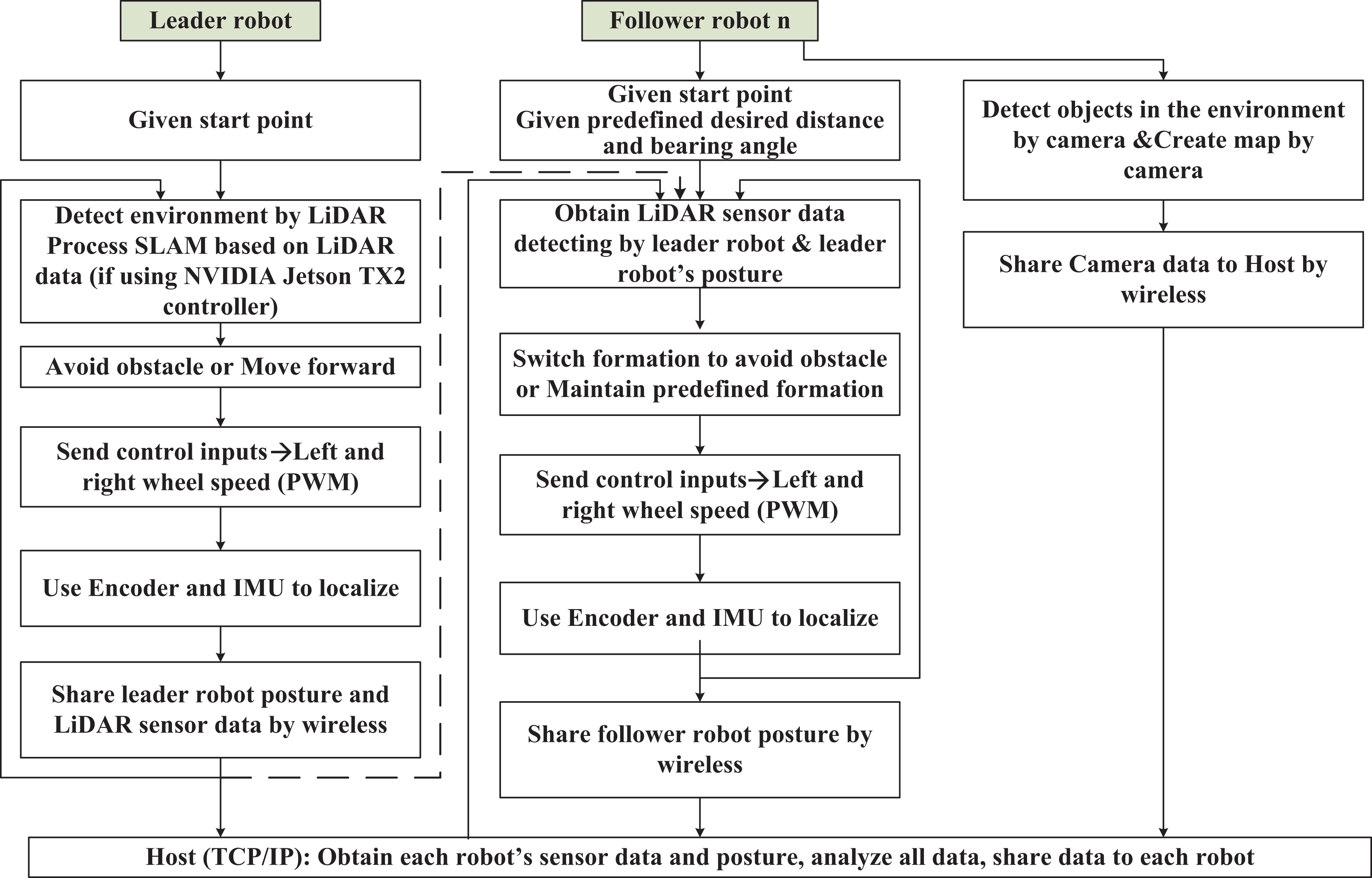
The IoRT system structure. IoRT: Internet of Robotic Things.
The leader robot’s control scenario is as follows: detects environment by the equipped LiDAR sensor; avoids obstacle or moves forward, depending on the LiDAR sensor’s data; if the leader robot uses the NVIDIA Jetson TX2 controller, it will process cartographer SLAM, based on LiDAR sensor data; sends a command to its motors to move; localizes itself using encoder and IMU; and shares its posture and LiDAR sensor data to the host controller by wireless module.
The follower robot’s control scenario is as follows: obtains shared LiDAR sensor data from the leader robot; switches formation to avoid an obstacle or maintains predefined formation; sends a command to its motors to move; localizes itself using encoder and IMU; shares follower robot posture by wireless module; and creates a map by a depth camera and shares camera sensor data to host by wireless module.
Although the follower robot is equipped with a depth camera, the horizontal field of view of the depth camera is 60 degree. It is difficult to get 360° environment information simultaneously. To plan safe path, the follower robot needs 360-degree environment information simultaneously. Therefore, the follower robot uses shared LiDAR sensor data from the leader robot to avoid obstacles.
The robot uses an ORBBEC Astra depth camera to build a 2D environment map. The horizontal field of view of the Astra camera is 60 degree. Choosing depth mode for Astra camera, it will show 640 × 480 depth image. The value of each pixel presents depth data, which is the distance from the camera to the object in millimeter. We use the central row (row 320) of the depth image data to generate a 2D map. As shown in Figure 2, the point


Map point H using ORBBEC Astra depth camera.
Therefore, yh is calculated as

In Figure 2,

Based on robot posture

Fuzzy sliding mode tracking control method
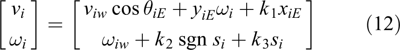
For robot motion control, two points should be considered such as reducing the calculation time and keeping the robot motion stable. To achieve these goals, we design a control input
Define the waypoint and the current state error as

If

where
The switching function si for robot Ri is as

The exponent reaching law is designed as

where
The control law is defined as
To prove the stability of the control law, the Lyapunov function is designed as

The derivative of the Lyapunov function is

When
If a moving point is far from the sliding surface, k 2 should be large to have fast trending motion from system status to sliding surface, if the moving point is close to the sliding surface, k 2 should be small to have slow trending motion from system status to sliding surface, to weaken the charting. Therefore, the fuzzy sliding mode controller is designed. The fuzzy rule is described in Table 1. Seven fuzzy sets are used to describe the fuzzy partitions, as positive big, positive medium, positive small, zero, negative small, negative medium, and negative big.
Fuzzy rule.

PB: positive big; PM: positive medium; PS: positive small; ZO: zero; NS: negative small; NM: negative medium; NB: negative big.
The triangular function is defined as

Using the centroid defuzzification method, the output is as

The fuzzy reaching law is defined as

Based on (8), the fuzzy sliding mode control law is as

Simulations
Figure 3 shows sinusoid trajectories of three robots, controlled by fuzzy sliding mode control algorithm. Three robots form triangle formation. The black line presents leader robot’s trajectory. Red line and blue line are the trajectory of follower robot 1 and follower robot 2, respectively. The parameter for the fuzzy sliding mode control method is 


The trajectory of three robots.
The state errors of leader robot, follower robot 1 and follower robot 2 are shown in Figures 4 to 6. At first time, follower robots track leader robot from their start points, error occurs. Three robots should form and maintain a triangle formation. The ideal paths for three robots are that three robots form and maintain triangle formation correctly. Initially, three robots are not located in the right triangle formation. Two follower robots should track leader robot and form triangle formation with leader robot. Therefore, error occurs. At t = 8 s, the errors converge to zero, it means follower robots correctly and stably maintain formation with leader robot.

Leader robot’s error.

Follower robot 1’s error.
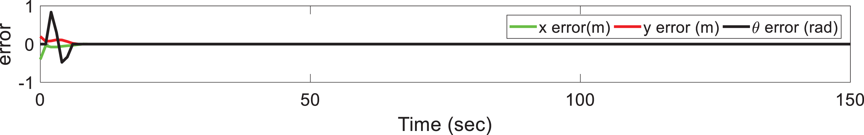
Follower robot 2’s error.
The simulation result in Figure 7 is used to compare with the experiment result. In Figure 7, the black lines are presented as obstacles, and the blue line and red line are shown as the trajectories of leader robot and follower robot, respectively. Initially, the desired distance and desired bearing angle between the leader and the follower robots is defined as 1 m and 90 degree, respectively. When the distance between the leader robot and the obstacle is small than 1.5 m, the leader robot avoids the obstacle. The follower robot switches safe formation by changing the desired distance and desired bearing angle with the leader robot.

Two robots avoid obstacles using safe leader–follower formation.
Experiment
The experiment is used to show the effectiveness of the proposed IoRT system, where leader and follower robots successfully finish five tasks: localizing themselves, planning paths, avoiding obstacles, stable moving to waypoint, and creating a map. Based on the IoRT system structure shown in Figure 1, we created the multiple robots IoRT system. As shown in Figure 8, the robot used in the experiment is the Kobuki mobile robot. The main processor is the NI myRIO controller with a wireless module. Two Kobuki robots localize themselves using encoder and IMU. The robot heading angle is measured by a Three-Axis Digital Gyroscope (Part Name: L3G4200D). Based on the literature, 32 figure in-place rotation test, the average error is in the range of −2.5 to 2 degree/rev. The errors of encoder and IMU result location error during the whole process. Therefore, we use fuzzy sliding mode tracking control method to minimize error. The leader robot is equipped with RPLiDAR A1 sensor to detect obstacles in the environment. The core of RPLiDAR A1 runs clockwise to perform a 360° omnidirectional laser range scanning for its surrounding environment. The detection range is 12 m. The sample rate is 8000 Sa/s. The angular resolution is 1°. The distance resolution is 0.2 cm. If the distance between the leader robot and an object is smaller than 1.5 m, the leader robot will avoid the obstacle by changing its orientation. The follower robot is equipped with ORBBEC Astra depth camera to create a depth map of the environment. Both leader and follower robots communicate with the host PC by wireless module. The algorithms are implemented in LabVIEW 2017 with Mathscript Module. The experiment platform is described in Figure 9. The DDS IoT application protocol is used to process the leader–follower formation control. The controller is master, and two Kobuki robots with myRIO controllers are clients. Master and clients communicate with each other by TCP/IP. The dash line between myRIO 1 and myRIO 2 presents that they will communicate with each other if the host controller fails.
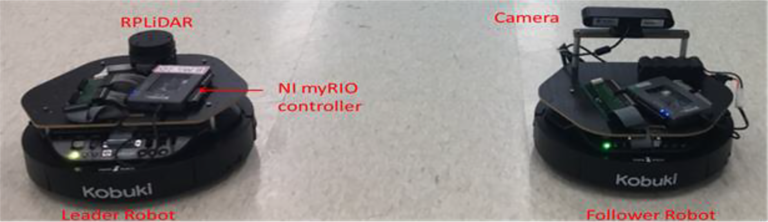
Two Kobuki mobile robots.

Experiment platform using Kobuki robots and sensors.
Two robots’ trajectories and LiDAR sensor’s data is shown in Figure 10, which is compared with Figure 7. Initially, two robots are located at

Two robots’ trajectories and LiDAR sensor’s data: (a) t = 17 s, (b) t = 44 s, (c) t = 60 s, and (d) t = 80 s. LiDAR: light detection and ranging.
The depth map from the camera is shown in Figure 11, based on the mapping algorithm in section “IoRT system structure.” Initially, we define a 600 × 600 grayscale image. The image pixel is equal to 70. The distance between two conjoint pixels is 1 cm in real world. After detecting by depth camera, the white space is presented as a free space. The black dot is present as the object detecting point. The red circle is presented as the robot.

Depth map from the follower robot.
If the leader robot is equipped with an NVIDIA Jetson TX2 controller, it will process cartographer SLAM, avoiding obstacles. Figure 12 shows the experiment result when testing in the corridor. The leader robot avoids obstacles, simultaneously localizes itself and builds a map.

Leader robot avoids obstacles and does SLAM with the NVIDIA Jetson TX2 controller.
Conclusions
This article proposed how to build an IoRT system for multiple mobile robots, to monitor events, fuse sensor data, use local robots to determine a best action, and then act to control multiple mobile robots. Multiple robots IoRT system finishes five tasks simultaneously, such as localizing themselves, planning paths, avoiding obstacles, moving to waypoint stable, and creating a map. A mapping method is discussed to create a map using depth camera’s data and robot’s posture. Based on LiDAR sensor data and Google cartographer, SLAM is also processed in this article. The fuzzy sliding mode tracking control method is used to minimize the robot’s tracking error. The simulation results prove the effectiveness of the proposed motion control algorithm. The experiment results show the effectiveness of proposed IoRT system structure. One host controller and two Kobuki mobile robots are integrated, and the robots successfully localize themselves, avoid obstacles, and build a map. In the future, we will consider to add more robots in the IoRT system and control them outdoor.
Footnotes
Declaration of conflicting interests
The author(s) declared no potential conflicts of interest with respect to the research, authorship, and/or publication of this article.
Funding
The author(s) disclosed receipt of the following financial support for the research, authorship, and/or publication of this article: This research was supported by Basic Science Research Program through the National Research Foundation of Korea (NRF) funded by the Ministry of Science [Grant Number 2017R1D1A3B04031864].