
Abstract
Aim to the problems of low load and precision of the serial manipulator used in casting operation. Casting execution equipment based on 2UPR-2RPU mechanism was designed. A prototype of heavy-duty casting robot has been proposed and developed. Based on the theory of robot topology, the mechanism constraint relation of the casting execution equipment was analyzed, and it is concluded that the casting actuator has three degrees of freedom. Both the inverse position equation of the casting execution equipment and axial velocity equation of branch chain were established. In this article, kinematics simulation of the casting execution equipment based on ADAMS software was presented, and its kinematics characteristics of each parallel branch chain were analyzed. The validity of this kinematics model of casting actuator was verified. Based on the working space analysis method for parallel mechanism, the working space range of casting execution equipment was simulated by the MATLAB software. This research provides a reference for expanding the application of hybrid structural robot in casting field and developing casting heavy-duty casting robotic products.
Keywords
Introduction
Compared with parallel manipulator, series manipulator has the characteristics of simple structure, high flexibility, convenient control, low cost, large movement space, and so on, and therefore they are widely used in many fields. 1 –3 There are some problems existing in the casting industry, such as low location accuracy, low load, low flexibility, difficulty transferring, and so on. 4 –6 On the contrary, the parallel mechanism has the characteristics of high motion accuracy, strong bearing capacity, and small motion inertia, 7 –10 which makes up for the deficiency of series manipulators in casting operations. Jia et al. 11 studied the dynamics of 3-RRPR flexible precision positioning worktable based on virtual work principle. Lu et al. 12 designed a five-degree-of-freedom (5-DOF) hybrid robot based on 2RPU/UPR parallel mechanism. And the scale and structure were also optimized. Zhu 13 and Liu 14 analyzed the 2PRU-UPR kinematics characteristics of parallel mechanism based on the spiral theory. Yano and Terashima, 15 Terashima and Yano, 16 Sugimoto, Yano, and Terashima, 17 and Noda and Terashima 18 designed the control system of tilting automatic pouring robot and proposed the method of monitoring and controlling of liquid metal pouring system.
The application research of parallel mechanism in casting equipment is relatively few. Most of the automatic casting equipment are characterized by complex structure and difficult to control. So they cannot meet the requirements of large and medium-sized casting operations. Aiming at the shortage of the existing pouring robot and combined with the advantages of parallel mechanism. In this paper, a 2UPR-2RPU parallel mechanism has been designed as the casting actuator of the hybrid heavy-duty casting robot.
In this presentation, based on 2UPR-2RPU parallel mechanism, a casting execution equipment of the heavy-duty casting robot has been designed and the kinematics model of the casting execution equipment has been established. The kinematics characteristics of casting execution equipment were analyzed with MATLAB R2014b and ADAMS 2013, Creo 2.0 software. A prototype of heavy-duty casting robot was developed. It provides theoretical reference for the design and product development of heavy-duty casting robot.
Mechanical structures of heavy-duty casting robot
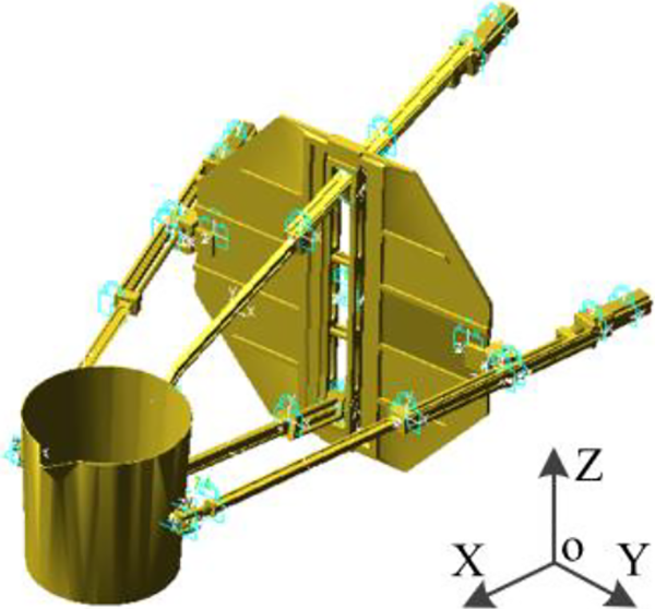
Combining the characteristics of series robot, such as simple structure, large workspace, and flexible operation, with the characteristics of the parallel robot, such as low inertia, large stiffness, and so on, a hybrid heavy-duty casting robot was designed and the prototype has been developed, as is shown in Figure 1. The mechanical structure of the heavy-duty casting robot is composed of the turning device, the lifting device, the counterweight device, and the casting execution equipment.

Prototype of heavy-duty casting robot. 1: lifting device; 2: turning device; 3: counterweight device; 4: casting execution equipment.
Figure 2 depicts the mechanical structures of the casting execution equipment of heavy-duty casting robot. It can be seen that it is mainly composed of casting ladle, four parallel branch chain modules, and branch chain mounting blocks. In the four parallel branched modules, the mechanical structure of the L 1 branched chain module is the same as that of the L 3 branched chain module, and both of them adopted the UPR structures. The mechanical structure of the L 2 branched chain module is the same as that of the branched module, and both of them adopted the RPU structures. The L 1 and L 3 branch chain modules are arranged in the up and down direction and installed on the branch chain mounting block. They are connected with the casting ladle by a combined rotating pairs, and connected with the branch chain mounting block by universal joint. The L 2 and L 4 branch chain modules are arranged symmetrically in the left and right directions on the branch chain mounting block. They are connected with the branch chain mounting block by rotating pair, and connected with the casting ladle by universal joint.

Schematic diagram of mechanical structure of casting executing equipment. 1: casting ladle; 2: L 1 branch chain modules; 3: L 2 branch chain modules; 4: L 3 branch chain modules; 5: L 4 branch chain modules; 6: combined rotating pairs; 7: branch chain mounting blocks.
Each branch chain module is composed of linear sliding table module and transmission bar. Servo motor to control linear slide table can adjust the position and gesture of the casting ladle. The position of the casting ladle in the X-direction is adjusted by synchronously controlling the movement of all the branch chain modules. Drive the L 2 and L 4 branch chain modules to move reverse synchronously to adjust the Y-direction of the casting ladle. Control the movement of the L 1 and L 3 branch chain modules to make the casting ladle rotate along its Y-axis and perform pouring operations.
Mechanism design of the casting execution equipment
Topological structure of casting execution equipment
According to the topological structure theories of the mechanism, 19 the 2UPR-2RPU parallel mechanism is selected as the casting actuator of the casting execution equipment. Branch chain mounting block is used as a static platform for casting execution actuator, and the casting ladle acts as the dynamic platform, as is shown in Figure 3.

Topological structure diagram of casting actuator.
On the static platform, the branched chains L 1 and L 3 are arranged symmetrically and have the same structure. R 11 and R 13 are coaxial. Axes of R 12 and R 32 are parallel to each other. On the moving platform, the branched chains L 2 and L 4 have the same structure. The axes R 14 and R 34 axes are parallel to each other. The axe R 24 is coaxial to R 44. And the axis R 14 is parallel to R 12. Set the four moving pairs P 13, P 33, P 22, and P 42 as the driving pairs.
Determination of DOF
The topological structure of the four branch chains in the casting execution actuator can be expressed as follows:
Single-opened-chain

POC set of branch end components is

POC set of the moving platform of casting execution actuator is
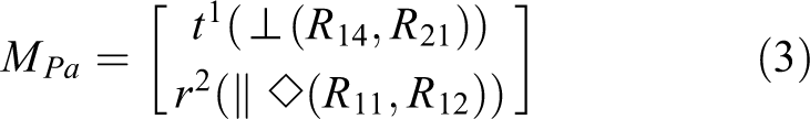
where
Kinematics analysis
Position analysis of casting execution equipment
The position analysis method of parallel mechanism
20
was adopted, and the reverse solution of casting execution actuator was established. RPY gesture representation is adopted to transform any vector in the


Schematic diagram of mechanism of casting execution actuator.
where c represents cosine and s represents sine.
The origin point P of the dynamic coordinate system can be expressed by cylindrical coordinate system as

Coordinates of each hinge point on the casting ladle and branch chain mounting block in the corresponding coordinate system can be expressed as
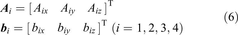
For

In the static coordinate system OXYZ, the length vector

Expand the formula, you can get

The position reverse solution equation of casting execution equipment is

Given the position and gesture of the casting ladle, the bar length of the parallel mechanism can be calculated according to equation (10).
Branch chain velocity analysis
According to the kinematics model, the rod length of the parallel branch chain is a function of the configuration of the casting ladle, and can be expressed as

where α, β, and γ are the rotation angle of the dynamic platform coordinate axes X′, Y′, and Z′ relative to the static coordinate axes X, Y, and Z, respectively. px , py , and pz are the coordinate value of the origin point of the dynamic platform coordinate system in the static coordinate system.
The inverse position equation of the casting execution actuators was established based on kinematics model. It is a function of ψ, θ, φ, r, and z, five parameters. ψ, θ, and φ represent the rotation angle of the dynamic platform coordinate axes X′, Y′, and Z′ relative to the static platform coordinate axes X, Y, and Z; r is the distance between the origin point of the static and dynamic coordinate system; and z is the coordinate value of the origin point P of the dynamic coordinate system on the Z-axis of the static coordinate system.
According to the topological structure analysis of the casting execution actuator, the casting ladle does not have the rotational DOF in X-direction and the moving DOF in Z-direction. Therefore, the rod length of the casting execution actuator is a function of θ, φ, and r, three parameters. The kinematics equation of the casting execution equipment can be expressed as

The reverse position solution of parallel branch chain of the casting execution actuator can be simplified as

Substitute equation (13) into equation (10), the reverse solution equation for the position of parallel branch chain of casting execution actuator can be expressed as

Take the derivative of equation (14), the axial velocity equation of the branch chain of the casting execution actuator can be written as

Define

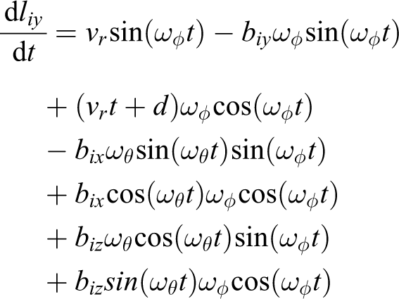


Establishment of axial velocity equation of branch chain of casting execution actuator provides a theoretical basis for the design of the casting execution actuator and the control of the dumping velocity of the casting ladle.
Kinematics simulation analysis
In this study, ADAMS software was adopted to simulate the motion process of the casting execution equipment of the heavy-duty casting robot. 21,22 First, a three-dimensional model of casting execution equipment has been established by Creo software. Then, import this model into ADAMS software, and complete material definition and parameter setting. Add constraint types and set drivers for each motion branch chain. Figure 5 gives the ADAMS model of casting execution actuator.
ADAMS model of casting execution device.
Set the casting ladle rotated around the Z-axis of the branch chain mounting block at the speed of 1° s−1. Make the casting ladle move 300 mm in the positive and negative direction of Y-axis, respectively. Displacement of hinged joints B 2 and B 4 and axial velocity of branch chains L 2 and L 4 were measured, as is shown in Figure 6. Figure 6(a) exhibits the variations of the displacement of the reference point P in the Y-direction with time. Figure 6(b) shows the changes of the rod length of branch chains L 2 and L 4. It can be seen from Figure 6(a) and (b) that the displacement of the casting ladle in the Y-direction and the rod length of the parallel branch chains L 2 and L 4 change linearly. Figure 6(c) and (d) illustrates the variations of the axial velocity of branch chains L 2 and L 4, respectively. It is evident that the variation tendency of axial velocity of the parallel branch chain L 2 is opposite to that of the parallel branch chain L 4.

Kinematic characteristics of each branch chain L 2 and L 4 during swing. (a) Displacement of the casting ladle in Y-direction, (b) changes of the Rod length of the branch chain L 2 and L 4, (c) variations of axial velocity of parallel branch chain L 2, (d) variations of axial velocity of parallel branch chain L 4.
Set the casting ladle rotated around its Y-axis to 90° at the speed of 1° s−1. Figure 7(a) gives the variations of rod length of branch chains L 1 and L 3. Figure 7(b) shows the axial velocity variation of branch chains L 1 and L 3. It was found that the rod length of branch chain L 1 changes linearly, while the rod length of branch chain L 3 first decreases, and then increases. The axial velocity of branch chain L 1 increases rapidly at first, and then decreases slightly. The axial velocity of branch chain L 3 decreases in the opposite direction and then increases in the positive direction.

Kinematic characteristics of branch chains L 1 and L 3 during dumping. (a) Changes of the Rod length of the branch chains L 1 and L 3, (b) changes of axial velocity of parallel branch chains L 1 and L 3.
It also can be seen from Figures 6 and 7 that the variation tendency of the rod length of each branch chain with time and the change trend of the axial velocity of the branch chain are consistent with the calculation results of the kinematics equation. This verified the validity of the kinematics equation of casting execution actuator.
Workspace analysis
Workspace constraints
The workspace analysis of the casting execution actuator can fix a certain gesture and partial position parameters of the casting ladle, and study the set of all possible locations of the casting ladle reference point P in space. 23 –25 The section shape of the workspace of casting execution actuator is determined, and the workspace of casting execution actuator is achieved. Factors affecting the workspace of the casting execution equipment include the following:
(1) Rod length
L min and L max are used to represent the minimum and maximum value of bar i, and the constraint of bar length can be expressed as

Define the boundaries of the working space that can be reached by the casting actuator by the movement limitation of the rod length.
(2) Angle of kinematic pair
The joints connected with casting ladle, branch chain mounting block, and each branch chain were universal joint and revolute pair. The connection between the branch chains L 1 and L 3 and casting ladle adopts revolute pair. The connection between the branch chains L 2 and L 4 and the branch chain mounting block adopts revolute pair. Other joints are universal joints. There are rotation angle limitations in these pairs of motion.
The constraint conditions of rotation angle of revolute pair can be expressed as

(3) Branch chain section size
The main reasons of mechanism interference are the geometric sizes of casting ladle, branch chain mounting block, and branch chain. It can be assumed that each branch chain section is cylindrical, and its diameter is D. Then the conditions of no interference between adjacent branch chains are that the axial distance between adjacent branch chains is greater than D, that is

The origin point P of the dynamic coordinate system on the casting ladle is selected as the reference point. When the gesture and range of positional parameters of the casting ladle were given, thus the length of each branch chain l i, joint angle θ, and the distance between adjacent branch chains D i can be calculated. The calculated results are compared with the allowable values of each parameter. If a calculated result exceeds its allowable value, the reference point P is outside the workspace. Conversely, the reference point P is inside the workspace. The graph composed of all reference points that satisfy the conditions is the workspace of casting execution actuator.
Determination of workspace
The size of the workspace depends on the rod lengths of L 2 and L 4 and the constraint conditions of the motion pair of the active branch chain. L 1 and L 3 were set as slave branched chains.
It can be seen from the determination of the DOF of the casting execution actuator that the rotational freedom in Y- and Z-direction and the freedom of movement in X-direction exist in the casting actuator. And the origin P of the dynamic platform was selected as the reference point of the casting ladle. As a result, there is no change in the position of the reference point of the casting ladle when the execution actuator rotates in the Y-direction. Therefore, the casting ladle is only located in the XY plane.
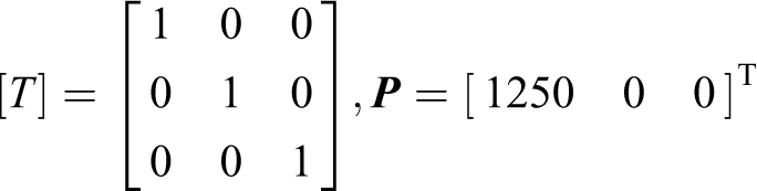
The position and gesture of the selected casting ladle relative to the branch chain mounting block can be expressed as
The limitation range of rod length variation of each parallel branch chain is

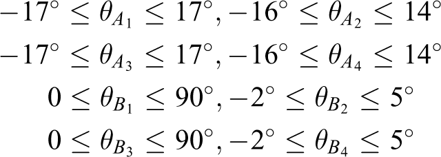
The limitation range of rotation angle of the motion pair A 1, A 2, A 3, B 1, B 2, B 3, and B 4 on the casting ladle and branch chain mounting block relative to the selected state is
MATLAB software was used to calculate the spatial position of reference point P in the XY plane, as shown in Figure 8(a). It can be seen from Figure 8(a) that the minimum distance from the reference point P of the casting ladle to the branch chain mounting block on the X-axis is 880 mm. The reciprocating distance of the casting ladle on the Y-axis increased with the increasing of the X-coordinate value. When x ≥ 1010 mm, the size of the motion space on the Y-axis remains unchanged, and the range of motion of the casting ladle in the Y-direction is [−300, 300].

Workspace of the casting executing device. (a) Range of motion in XY plane, (b) three dimensional drawing of workspace, (c) range of motion in XZ plane, (d) range of motion in YZ plane.
The three-dimensional workspace is formed when the branch chain mounting block moves up and down (Figure 8(b)). It is evident that the workspace of the casting ladle remains the same along the X–Y cross section. Figure 8(c) and (d) gives the workspace of the casting ladle in XZ-direction and the YZ-direction, respectively. When the branch chain mounting block moves up 150 mm along the Z-axis and reaches the limitation of Z-direction, the accessible motion position of the casting ladle reference point P is shown in Figure 8(b) to (d). From Figure 8(c) and (d), it can be seen that the maximum value of the reference point of the casting ladle along the Z-direction is 150 mm, and the X-direction is 1250 mm.
Conclusions
Based on the topological structure theory of the mechanism, 2UPR-2RPU parallel mechanism was selected as the casting execution actuator of the heavy-duty casting robot. It is determined that the casting execution actuator has three motion DOF, namely the rotational freedom around Y- and Z-direction and the freedom of movement along X-direction. In this article, the prototype of heavy-duty casting robot has been designed and developed. This prototype has a compact structure and meets the requirements of casting operation. The experimental results indicate that the freedom of movement of the prototype is consistent with the calculation results of the model. The casting ladle moves smoothly in the X- and Z-direction. And rotation in the Y-direction is affected by the mode of motion of the branch chain L 3. The sharp return point can be avoided by optimizing the location and control strategy of the casting ladle hinge point, so as to avoid the fluctuation of liquid level during pouring operation.
The inverse position equation of the casting execution actuator and axial moving velocity equation of parallel branch chain were established. The movement of the casting execution equipment was simulated by ADAMS software. The kinematics characteristic curve of parallel branch chain was obtained. The axial velocity of the branch chains L 2 and L 4 varies from 9.4 mm s−1 to 10.4 mm s−1. The rod length of its branch chain changes linearly and the motion control is simple. The linearity of rod length change of branch chains L 1 and L 3 is low, and the movement control is difficult. The research results provide theoretical basis and practical reference for the design and control of heavy-duty casting robot.
The workspace analysis method of robotic parallel mechanism was adopted. The workspace of casting execution device was drawn by MATLAB software, and range of motion of casting execution actuator is given. The maximum and minimum distance between the casting ladle and the branch chain mounting block is 1240 mm and 880 mm, respectively. The sectional area of the workspace of the casting execution actuator in the Z-direction is constant.
Footnotes
Declaration of conflicting interests
The author(s) declared no potential conflicts of interest with respect to the research, authorship, and/or publication of this article.
Funding
The author(s) disclosed receipt of the following financial support for the research, authorship, and/or publication of this article: This work was supported by the Major Science and Technology Projects of Anhui Province of China (no. 16030901012) and Key Research and Development Plan Project of Anhui Province of China (no. 201904a05020092).