
Abstract
Lower mobility parallel mechanisms have been developed in different structures and widely applied in industry, but still have disadvantages in various tasks and functional requirements. A 2-PrRS-PR(P)S metamorphic parallel mechanism with two working configurations and a transiting configuration is presented. First, the architecture and the way of metamorphosis about the mechanism are described in detail. The mobility of the metamorphic parallel mechanism is obtained with screw theory. Furthermore, the parasitic motions in different configurations are derived based on the geometry constraint conditions. Both the inverse kinematic problem and forward kinematic problem of the mechanism are investigated by the closed-loop equation and validated via numerical examples. Then, the velocity and acceleration in two working configurations are obtained by the derivation of the inverse kinematic problem. Finally, the reachable orientation workspaces are discussed using the three-dimensional search method in different configurations. A comparison with the 3-PRS PM without metamorphic mechanism in workspace is presented and an example of the metamorphic parallel mechanism in robotic supporting leg is presented. The above analyses provide theoretical foundations for application of this mechanism.
Introduction
Inheriting the virtues of parallel mechanisms (PMs) in low inertia, high stiffness-weight ratio, and better kinematic and dynamic capacity, the lower mobility parallel mechanism (PM), whose degree of freedom (DOF) is less than 6, also has the advantages of simpler mechanical assembly and larger workspace and has attracted much more attention from researchers. In recent years, lots of literatures about lower mobility PMs have been achieved from researchers, such as synthesis and design theories1–3 and indexes for optimization of kinemics and dynamics.4–7 As a result of continuous research, several kinds of lower mobility PMs have been extensively applied in industry. The Sprint Z3 tool head, 8 the Exechon machine tool, 9 and the Delta robot 10 are good examples that obtained practical application in metal machining, goods sorting, and spacecraft simulating.
During the working process, a lower mobility PM has fixed configuration and mobility, which is difficult to adapt to the changing demand in industrial application. Metamorphic mechanism is a kind of mechanism that can perform different configurations by changing the topological structure and has better adaptability in various tasks and functional requirements. Combining the characteristics of the lower mobility PMs and metamorphic mechanisms, lots of metamorphic parallel mechanisms (MPMs) are produced and deliver better development in parallel mechanisms. It has been proven a new way to meet various requirements in industry.11–13
There are two ways to achieve MPMs: transforming the number of links and increasing geometric constraint to joints. 14 By adding an extra rotational DOF to a Hooke and revolute joint, Gan et al. presented a reconfigurable Hooke (rT) joint and revolute (rR) joint. According to these two types of reconfigurable joints and the distribution of the limbs, different configurations with different mobilities can be obtained, such as 3rTPS, 3rTCrT, 3rRPS, and 3SPS-1rTPrT.15–18 Zhang et al.19,20 presented a variable-axis (vA) joint and two types of 3SvPSv MPM which can change the configurations due to different constraints and phases, such as SvPSv, UvPSv, RvPSv, and UvPUv-I.
The most important issue for a study of MPM is the kinematic analysis, which is also the basis for the application of the MPM. For the various mechanisms mentioned above, many kinematic efforts in different configurations, such as mobility analysis, parasitic motion, the inverse kinematics problem, forward kinematics problem, and Jacobian matrices, have been devoted separately. Analysis of the singularity and workspace are also carried out in different configurations.
This article presents a 2-PrRS-PR(P)S MPM and focuses on the analysis of the kinematics issues. The remainder of this article is organized as follows. In section “Architecture description and mobility analysis,” the architecture and the way of metamorphosis about the mechanism are described. With screw theory, the mobility analyses are carried out. In section “Kinematic problem,” the kinematic modeling including the inverse kinematic problem (IKP), the forward kinematic problem (FKP), and the parasitic motions are analyzed and validated via numerical examples. Section “Velocity and acceleration analysis” states the velocity and acceleration analysis in two working configurations. Contrasting with normal 3-PRS PM, the workspaces of the mechanism are obtained in section “Workspace analysis.” An example of application is presented. The conclusion is arranged in section “Conclusion.” The analysis of this mechanism provides basis of modeling and optimal design for further applications.
Architecture description and mobility analysis
Architecture description
Based on the theory of metamorphic mechanism that the variation of kinematic pairs’ orientation can lead to configuration transition, a novel parallel metamorphic mechanism of 2-PrRS-PR(P)S is proposed. The 2-PrRS-PR(P)S mechanism includes a moving platform, three limbs, and a static base. The structure of limb 1 is PR(P)S. (P) is a metamorphic prismatic joint which can extend or retract under tension or pressure. A rR metamorphic joint which can change its orientation of the revolute axis is installed in limb 2 and limb 3. P represents prismatic pair, R represents revolute pair, S represents spherical pair, and rR represents metamorphic joint. The three-dimensional (3D) model of the three configurations is presented in Figure 1(a)–(c).
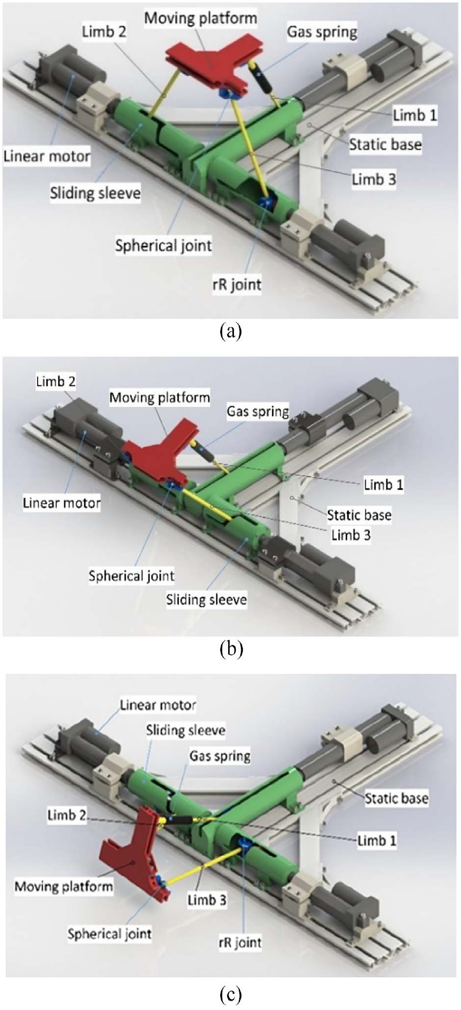
The 2-PrRS-PR(P)S mechanism model in (a) configuration 1, (b) configuration 2, and (c) configuration 3.
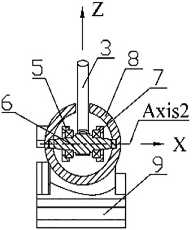
Limb 2 and limb 3 share the same structure. The partial section view of limb 3 is presented in Figure 2, and the profile view of limb 3 is presented in Figure 3. The spherical joint is connected with moving platform. The rR joint is an assembly mainly composed of a flange, a rotating shaft, an inner shaft, a U-type connection, and so on. The flange and linear motor is fixed by connecting piece. There are two bearings in the flange and the inner shaft is connected to these bearings. So the shaft can rotate in the flange around axis 1. The U-type connection is fixed on the end surface of the inner shaft. There are other two bearings in the U-type connection and the rotating shaft is connected to these bearings. The rotating shaft can rotate around axis 2 in the U-type connection. From the above, the rR joint has two axes of revolution which are axis 1 and axis 2 as shown in Figures 2 and 3.

The partial section view of limb 3.

The profile view of limb 3.
The partial section view of limb 1 is presented in Figure 4, and the profile view of limb 1 is presented in Figure 5. Compared with limb 2 and limb 3, only the connecting piece and bearing are removed. The spherical joint is connected with moving platform. The spherical joint and the rotating shaft are connected by a gas spring, which has two lengths to adjust under the tension or pressure and acting as (P) in limb 1.

The partial section view of limb 1.
The profile view of limb 1.
The simplified structure of assembly of sliding sleeve is depicted in Figure 6. There are two guide grooves in inner surface (see the cyan curve in Figure 6) which have central symmetry about the axis 1 and an outside slot (see the red curve in Figure 6) which is similar to the guide groove in shape. One guide groove is divided into three sections (Figure 6), including two straight lines (a) and (c) and a quarter helical line (b). The straight line (a) sited on the side surface and the straight line (c) sited on the top/bottom surface. Two straight lines are connected by the helical line (b).
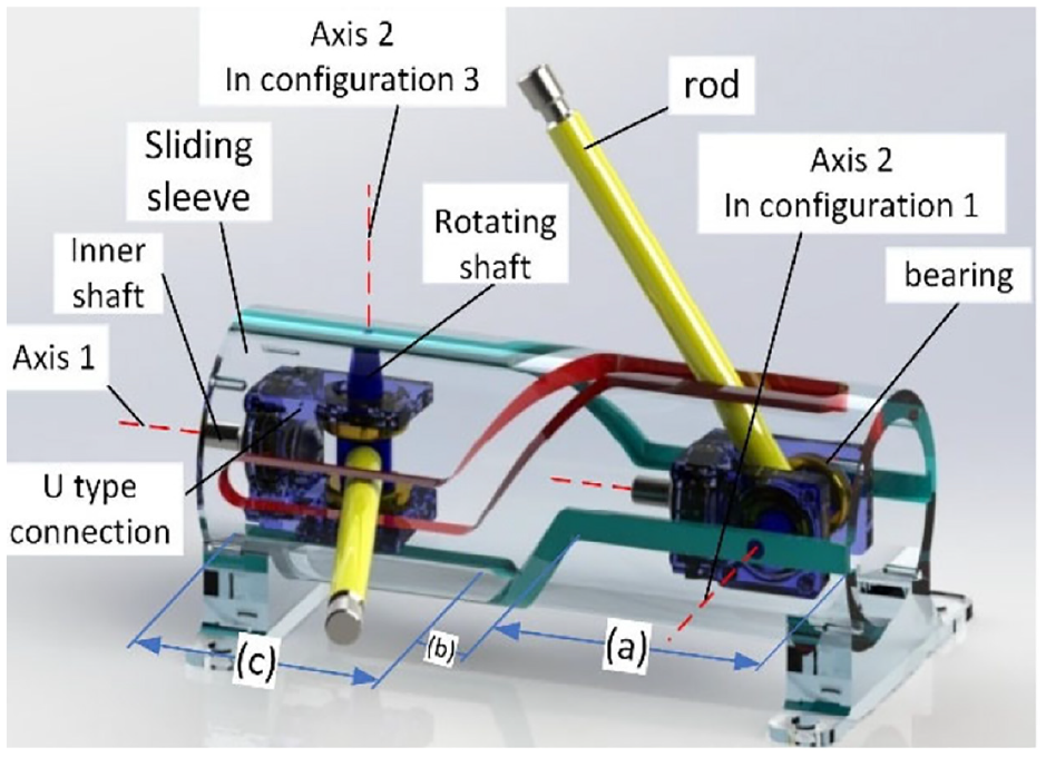
The simplified structure of assembly of sliding sleeve.
The changing process is as follows: three linear motors are used as three prismatic pairs. When the rR joint of limb 2 and limb 3 is situated in the first straight line (a), the axis 2 of the rR joint is parallel to the static base and this is configuration 1. Using the driving of the linear motors in limb 2 and limb 3, the rR joint of limb 2 and 3 get into the helical line (b) and this is configuration 2. When the rR joint passes through the transition and gets into the second straight line (c), the axis 2 of the rR joint is vertical to the static base, the gas spring in limb 1 is unlocked and extended under tension, and this is configuration 3. The configurations 1 and 3 are working configuration while the configuration 2 is just a transition. The working configurations are mainly analyzed in the article.
The kinematic diagram of the 2-PrRS-PR(P)S MPM is depicted in Figure 7. A global coordinate frame is established on the static base. Origin

Kinematic diagram of 2-PrRS-PR(P)S mechanism.
Mobility analysis
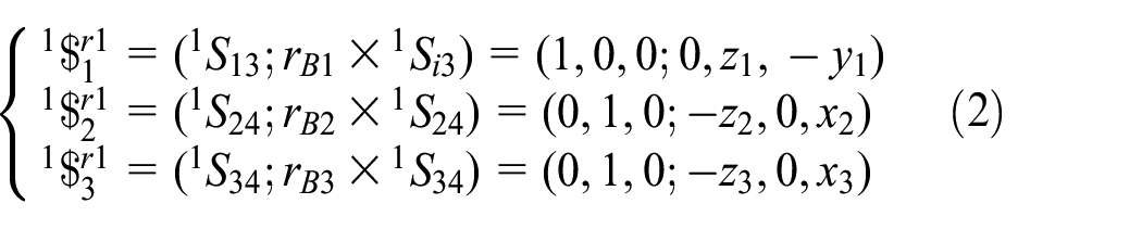
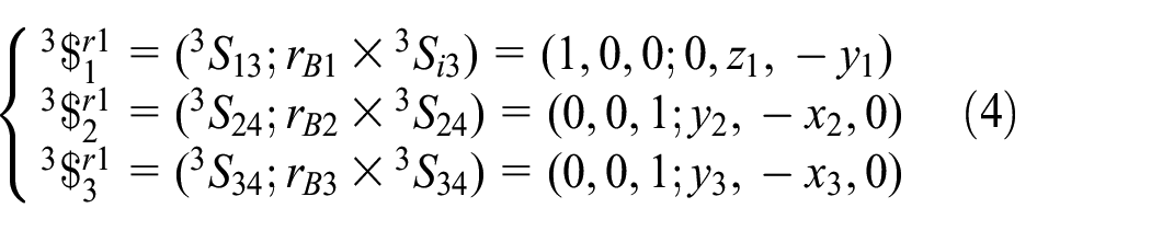
The screw theory has been applied to analyze the DOFs of the 2-PrRS-PR(P)S MPM in two working configuration. From the local frame,
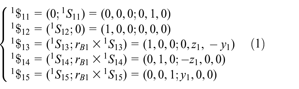
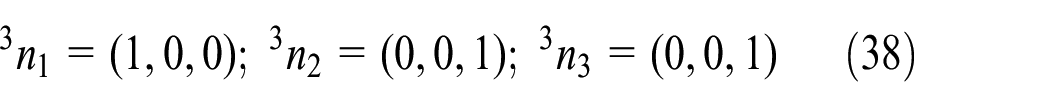
where 1 on the pre-superscript represents the configuration 1.

The sketch of limb 1 in configuration 1.
Similarly, the twist screws of the motion pair in configuration 3 can be obtained. The twist screws in limb 1 are the same as in configuration 1. The coordinate of


The sketch of limb 2 in configuration 3.
The twist screws of the motion pair in limb 3 are the same as in limb 2.
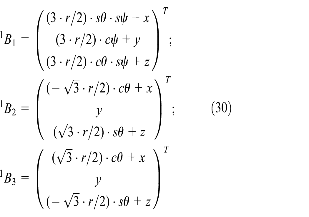
Then the constraint screws are
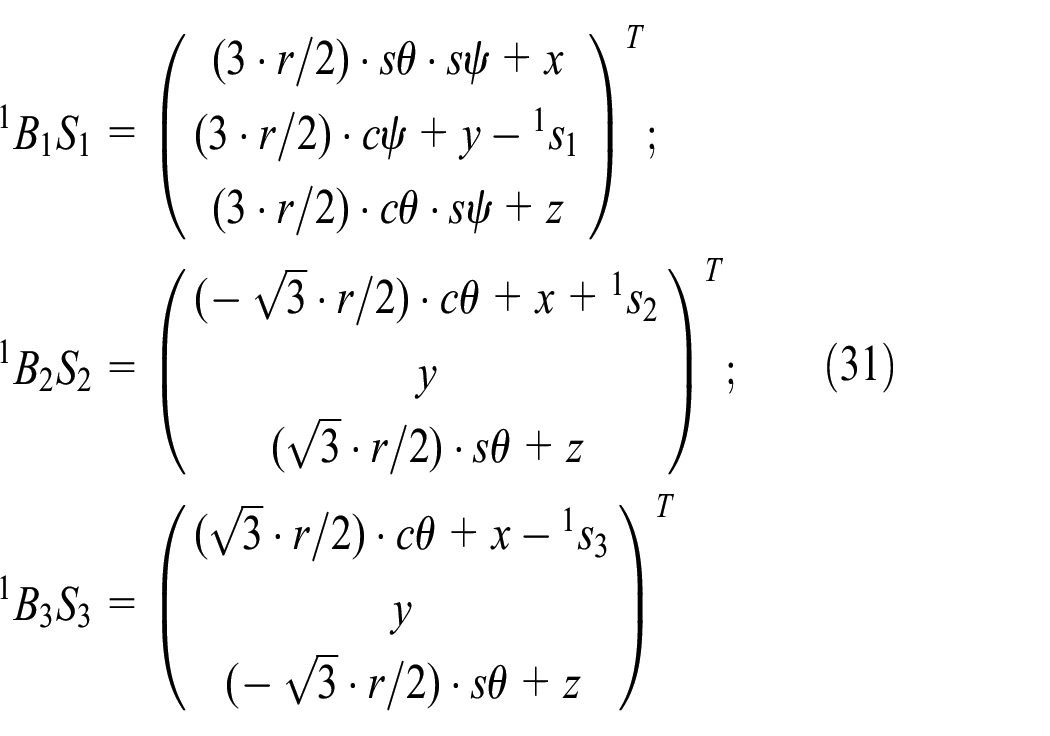
Kinematic problem
Kinematic problem includes inverse kinematics problem (IKP) and FKP. IKP is the primal problem for a mechanism that solves the input variables
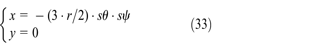
Parasitic motion
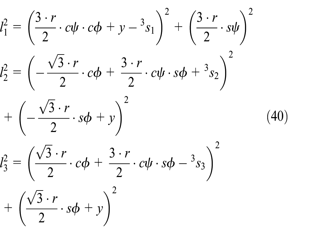
Analyzing the structure of the 2-PrRS-PR(P)S mechanism shown in Figure 2, the motion of single limb is restricted to motion in a plane which is perpendicular to the rotation axis of the revolute joint and can be defined as the geometrical constraint.
As depicted in Figure 2, the position vector of

Thus, there are

where

From equations (5) to –(7), we obtain equation (8) as follows
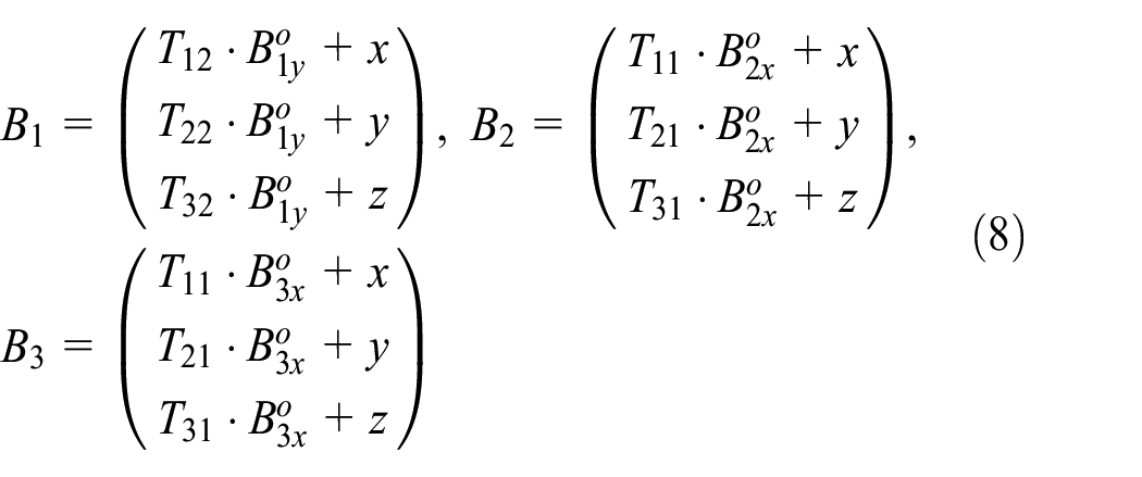
And

Then, the vector of

Depicted in Figure 10, assume that the angle between the axis of the revolute joint and the static base is


The angle of
The constraint condition of the mechanism is

Substituting equations (10) and (11) into equation (12), it yields
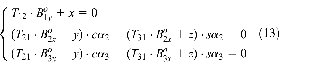
Then, we can analyze the parasitic motion in different configurations.
Parasitic motion in configuration 1
In configuration 1,

Substituting equation (5) into equation (14), equation (14) can be transformed to


We take x, y, and

Equation (18) shows that there is only one parasitic motion in configuration 1, which is prismatic motion along the x-axis
Parasitic motion in configuration 3
In configuration 3,

Substituting equation (5) into equation (19), equation (19) can be transformed to


We take x, z, and

Equation (23) shows that there is only one parasitic motion in configuration 3, which is also prismatic motion along the x-axis.
Parasitic motion in configuration 2
As we know, configuration 2 is a transition from configuration 1 to configuration 3. The angle of the revolute axis can change at the same time. Assume

which can be transformed to


Then, we can obtain

Parasitic motion in three configurations can be calculated by equations (19), (23), and (28). The orientation range is

The relationship between parasitic motion

The relationship between parasitic motion
The relationship between parasitic motion

The relationship between parasitic motion
As we can see from Figure 11, the maximum and the minimum magnitudes of the prismatic motion in configuration 1 along the x-axis happen at four end points of
Figure 12 shows that in configuration 3 the maximum and the minimum magnitudes of the prismatic motion along the x-axis happen at side boundary of the plane.
As depicted in Figures 13 and 14, the extreme value of the prismatic motion
IKP
The position vector of the origin point in moving coordinate is P with respect to global coordinate and can be written as
Configuration 1
In configuration 1, the moving platform has 3 DOFs, which are 2 DOFs of revolution around X-axis and Y-axis and 1 DOF of translation along Z-axis. The rotation matrix is

Thus, equation (8) can be expressed as
The vector of
The unit vector of the axis of revolute pair in three limbs can be written as

Thus, equation (14) can be expressed as
In addition, the fixed length constraint of three limbs is

which can be expressed as

Configuration 3
In configuration 3, the rotation matrix is

Similar to configuration 1, the vector of

The unit vector of the axis of three revolute pairs is
Thus, equation (24) can be expressed as

The fixed length constraint of three limbs can be expressed as
FKP
Given the actuated inputs
Figures 15 and 16 show the definition of


Local coordinate of limb 1.

Local coordinate of limb 2 and limb 3.
Considering the geometric edge length of the moving platform is fixed, we can get the constraint equation

And this equation can be derived as

where
where
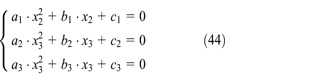
Eliminating

Equation (45) can be transformed as

Multiply equation (46) with

The characteristic determinant is
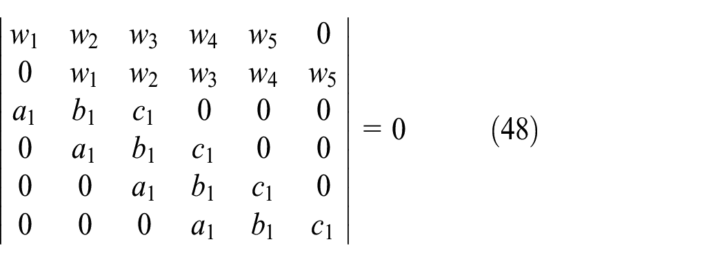
Expanding equation (48) results in 16th-degree polynomial in


Consequently,
Numerical verification
Parameters of the MPM in configuration 1 are given as
Using the analysis of FKP and with MATLAB program, equation (48) can be written as

The results for equation (51) contain four real roots of
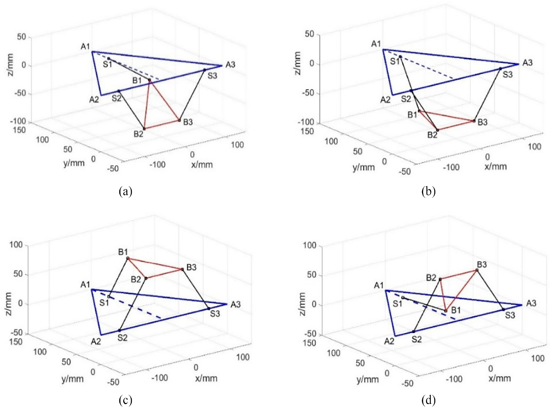
(a) Pose 1 in configuration 1, (b) pose 2 in configuration 1, (c) pose 3 in configuration 1, and (d) pose 4 in configuration 1.
Velocity and acceleration analysis
Velocity analysis
The velocity analysis of the mechanism is to gain the velocities of the prismatic pair from a given velocity of the moving platform. The velocity solutions of the mechanism are expressed below.
Velocity analysis in configuration 1
From equation (34), we can get the inverse kinematic equations in configuration 1.
Let
Taking the derivative of both sides of equation (35) with respect to time deduces

where
The elements in the matrix are the function of parameters of
When the manipulator is not in singular configuration, we can get

where
Velocity analysis in configuration 3
Similar to configuration 1, we can get the inverse kinematic equations from equation (40).
Let
Taking the derivative of both sides of equation (40) with respect to time deduces

where
The elements in the matrix are the function of parameters of
Also we can obtain

where
Acceleration analysis
Similar to the analysis of velocity of the mechanism, acceleration analysis also falls into two parts: configuration 1 and configuration 3.
Configuration 1
Taking the derivative of both sides of equation (53) with respect to time deduces

Thus, we have
where
Configuration 3
Taking the derivative of both sides of equation (55) with respect to time deduces

Thus, we have

where
Workspace analysis
Constraint conditions
The reachable workspace analysis can be obtained by the inverse kinematics problem (IKP) and can be classified into two types: position workspace and orientation workspace.
According to the characteristic of the mechanism, the constraint conditions include the displacement of the prismatic pair, rod length of three limbs, rotation range of the spherical pair and revolute pair, circumradius of the moving platform, and so on. The major factors are as follows.
Displacement of prismatic pair
The displacement of prismatic pair consists of configuration 1, configuration 3, and configuration of transition. When the total displacement and transitional displacement are fixed, the displacement of configuration 1 and configuration 3 will influence each other.
The constraint conditions are

where
Rod length of the limbs
The rod length of the limbs is one of the main parameters that can affect the workspace. The constraint condition is

where
Rotation range of the spherical pair and revolute pair
In this mechanism, every limb has a spherical pair and a revolute pair, and the range of their rotation angle is limited in practice.
Define

where
Define

where
Furthermore, the installation angle of the spherical pair affects the workspace of the mechanism, but when the structures are determined, the installation angle is fixed and has no influence.
Solving model of the workspace
The reachable position workspace is almost straight line if the original point of the moving platform is the reference point. The reachable orientation workspace is analyzed using the 3D search method. The flow diagram of the solving model of workspace is depicted in Figure 18.
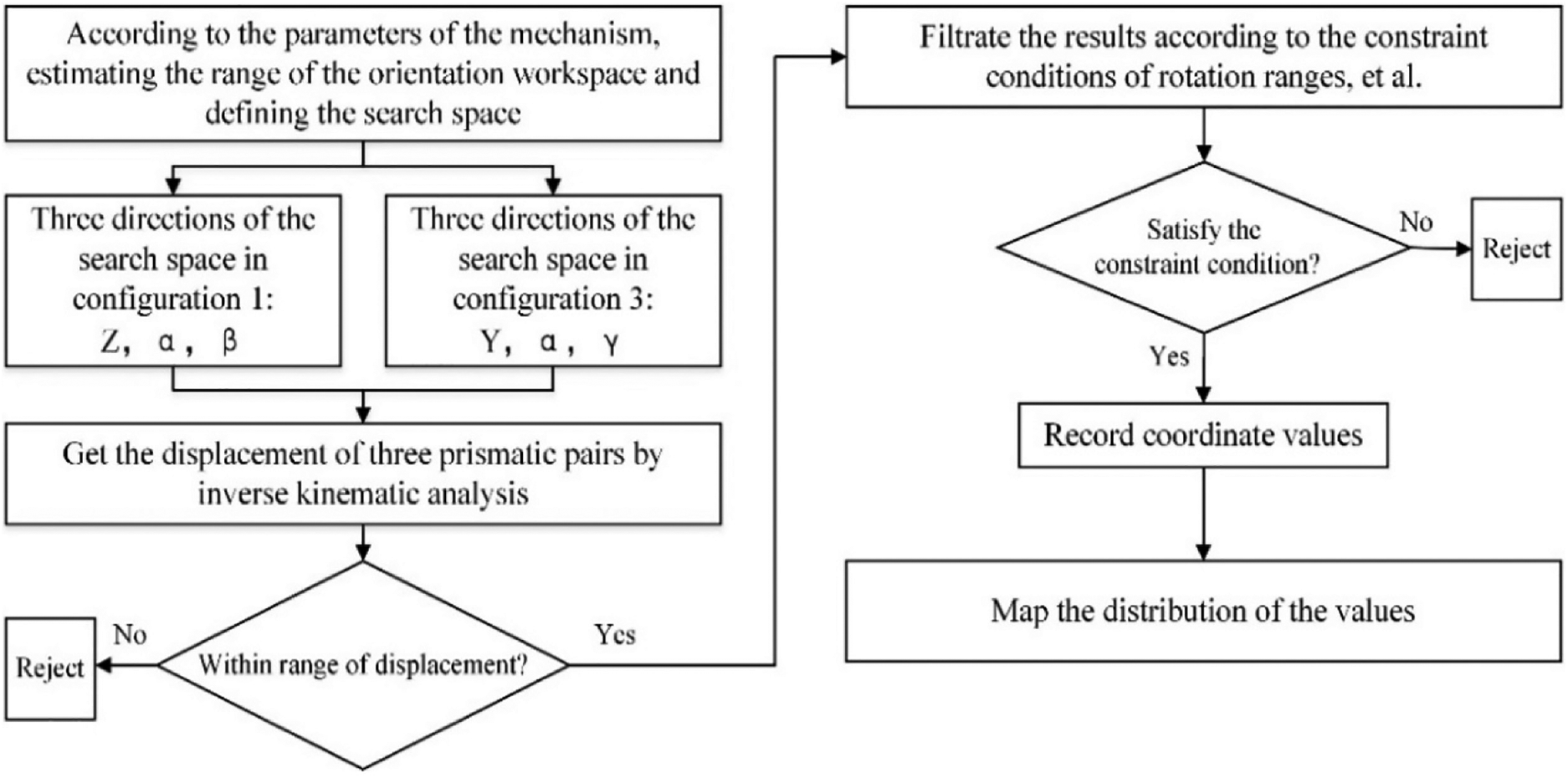
Flow diagram of solving model of workspace.
Reachable orientation workspace
In this subsection, a case study is proposed to show the reachable orientation workspace of the 2-PrRS-PR(P)S MPM. The geometrical and constraint parameters are presented in Table 1.
Geometrical and constraint parameters.

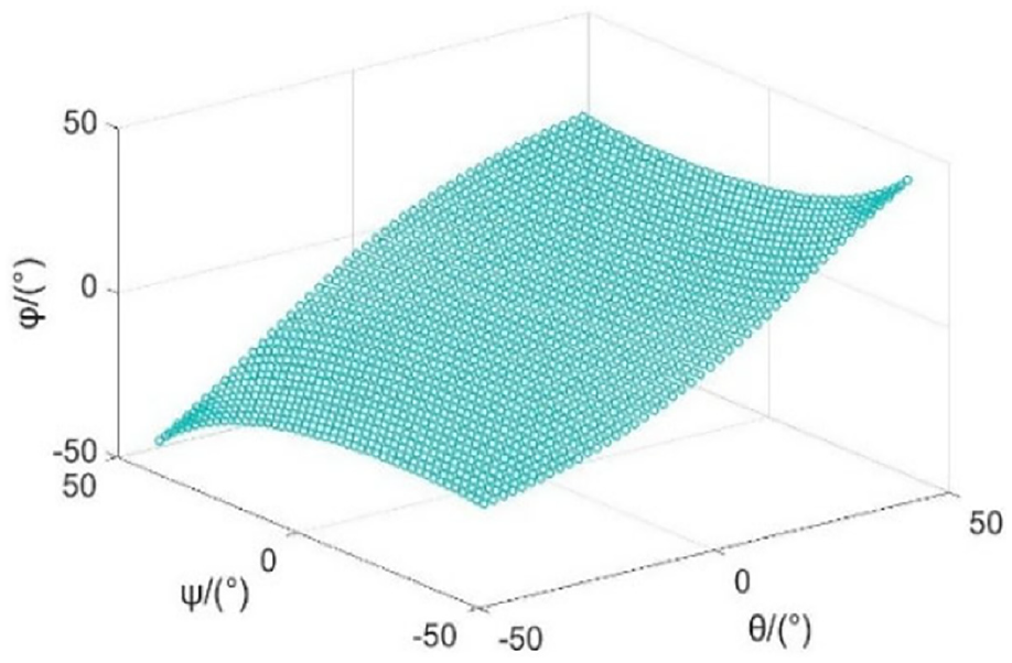
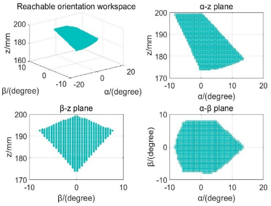
The reachable workspace of the 2-PrRS-PR(P)S MPM is analyzed by numerical examples, and the workspace shape is shown in Figure 19(a) and (b).

(a) Workspace in configuration 1 and (b) workspace in configuration 3.
From the dots clouds demonstrated in Figure 19, we can see that the rotation angles are
By contrasting the 3-PRS mechanisms without metamorphic configuration in same constraint conditions, the dots clouds of the workspace are shown in Figure 20.
Workspace in 3-PRS without metamorphic configuration.
We can see that the rotation angles are
An example for application in robotic supporting leg
As depicted in Figure 21, the abovementioned MPM installed in front of a wheel-tracked robot has a supporting leg and there is a wheel installed on the moving platform of the MPM. Two retractable wheels are mounted at the rear and two fixed wheels are mounted on the top of the robot. With the displacement along the Z directions in configuration 1 of the MPM and the extend retract of the rear wheels, the wheel-tracked robot can go through pipes of different diameters and avoid collision with the inner wall of the pipe (see Figure 21(a) and side view in Figure 21(b)). Also, the robot can realize wheeled motion when the road is flat (see Figure 21(c)). When the MPM is in configuration 3 and the rear wheels are contracted and hided in the robot, the robot can move with tracks. With the displacement along the Y direction in configuration 3 and the rotation in X direction in transiting configuration of the MPM, the robot can surmount obstacles of different heights and maintain stability with the aid of the supporting leg (see Figure 21(d)). Thus, we can see that the different working configurations have positive significance in improving the flexibility of the MPM and robotic supporting leg.

(a) Wheel-tracked robot in pipe, (b) side view of the robot in pipe, (c) wheeled motion on the ground, and (d) surmount obstacle.
Conclusion
This article presented a 2-PrRS-PR(P)S MPM with two working configurations and a transiting configuration. A detailed description about its architecture and the way of metamorphosis are proposed. The mobility of the MPM has been obtained in different configurations with screw theory which are two revolutions around X-axis and Y-axis and a translation along Z-axis in configuration 1 and two revolutions around X-axis and Z-axis and a translation along Y-axis in configuration 3.
According to the geometry constraint conditions, the parasitic motion in different configurations of the moving platform is analyzed. Then, the IKP and FKP of the mechanism are investigated by the closed-loop equation and validated via numerical examples. The velocity and acceleration in two working configurations are obtained by the derivation of closed-loop equation in the IKP.
The reachable orientation workspace is discussed using the 3D search method in different configurations. Compared with the 3-PRS PM without metamorphosis, the workspace is little smaller in configuration 1, but it can reach another position and orientation in configuration 3 that 3-PRS PM cannot get. An application of a robotic supporting leg is presented using the advantages of two working configurations. The analysis in this article verified its feasibility for applying this MPM in the varied requirements and environments in industry, especially in goods sorting and handling, turnover mechanism, robotic legs, and so on.
Footnotes
Handling Editor: Jixiang Yang
Declaration of conflicting interests
The author(s) declared no potential conflicts of interest with respect to the research, authorship, and/or publication of this article.
Funding
The author(s) disclosed receipt of the following financial support for the research, authorship, and/or publication of this article: This work was supported by the National Natural Science Foundation of China (NSFC) (Grant No. 51705412), the Natural Science Basic Research Plan in Shaanxi Province of China (Program No. 2015JM5235), and the Key Laboratory of Embedded System and Service Computing, China Ministry of Education (ESSCKF 2015-04), and Scientific Research Program Funded by Shaanxi Provincial Education Department (Program No. 16JF019).