
Abstract
The kinematics of robot wrist refers to the motion information of a manipulator, such as positions, velocities, and accelerations. It is very crucial for analysing the behaviour of robot wrist using a suitable kinematics model with a result of many valuable contributions. However, current researches always focus on full-actuated robot wrist. The proposed underactuated robot wrist is a novel mechanism with small volume, lightweight, low cost, low energy consumption, and high flexibility, thus designing a robot wrist with fewer actuators than the degrees of freedom becomes an important issue. This article is devoted to kinematics analysis model of a novel underactuated robot wrist. After the novel understated robot wrist was introduced, the inverse kinematics analysis and forward kinematic analysis of the underactuated robot wrist with numerical simulation based on virtual prototyping were discussed in detail. The verification of the forward kinematic analysis and inverse kinematics analysis is used to demonstrate the proposed methodology.
Introduction
The manipulator kinematics1,2 is involved in the position and orientation relationship between the end of the actuator and joint variables, which relates to the position3,4 and gesture of moving objects.5,6 The manipulator kinematics includes forward kinematics 7 and inverse kinematics. 8 The former is to solve the position and orientation of the end of the manipulator actuator with joint variables, while the latter is to solve manipulator joint angles with the position and orientation of the end of the manipulator actuator to the trajectory planning and motion control.6,9
According to the relationship between the degrees of freedom (DOFs) and the number of actuators, the mechanism can be divided into full-actuated mechanism, redundant-actuated mechanism, and underactuated mechanism.10,11 In a traditional full-actuated robot, motors are always fixed in the joints with the most weight of the whole robot. Thus, it might have some difficulties to apply a heavy multi-joint robot in some extreme industrial applications. Optimization and lightweight materials are general approaches to the lightweight of the robot. While the underactuated mechanism is a new approach to this topic, as its mechanical system has fewer actuators than its DOFs,12,13 with small volume, lightweight, low cost, low energy consumption, and high flexibility, thus causing widespread concerns in space robots, underwater robots, other flexible robots, and so on. The robot’s capabilities to achieve a certain posture in the workspace through a robot arm, while the robot wrist with serial mechanism 14 or parallel mechanism,15 –19 is an important connection between arm and end effector. Existing robot wrist has generally 3 DOFs with three motors. Generally, many underactuated robots 20 consist of underactuated mechanisms, 12 such as differential mechanisms, 21 compliant mechanisms, 22 triggered mechanisms, 23 and passive mechanisms. 24
However, current researches always focus on full-actuated robot wrist, while the underactuated robot wrist is a novel mechanism that has small volume, lightweight, low cost, low energy consumption, and high flexibility. Thus, to reduce bulk, lightweight, and expense, designing a robot wrist with fewer actuators than the DOFs becomes feasible by introducing mechanical elements that lead to non-holonomic constraints.25,26 In any case, achieving a formulation for the kinematics of the underactuated robot wrist is essential to its applicability. The aim of kinematics analysis for underactuated robot wrist is to study the relationship between the input angle of the actuator and the pose (position and orientation) of the moving platform, which specifically includes forward kinematics analysis (FKA) and inverse kinematics analysis (IKA). The difference between kinematics of underactuated mechanisms and full-actuated mechanisms is that in the derivation on FKA of underactuated mechanism, free joint angle value (i.e. passive joints) is assumed as a driving variable, which requires a separated sensor to detect. The detection values of angle sensor and drive joint angle variable values derive FKA of the underactuated mechanism. In the IKA, the passive joint value is as value of desired angle sensor detection.
The remainder of this article is organized as follows. Section ‘Introduction of a novel underactuated robot wrist’ introduces a novel underactuated robot wrist. Section ‘IKA of the underactuated robot wrist’ provides IKA of the underactuated robot wrist. Section ‘FKA of the underactuated wrist’ provides FKA of the underactuated wrist. Section ‘Kinematics numerical simulation based on virtual prototyping’ simulates virtual prototyping–based kinematics model to verify the results of above kinematic analysis. Section ‘Conclusion’ concludes this article.
Introduction of a novel underactuated robot wrist
Introduction of underactuated robot wrist
The present mechanism, which has been authorized for patent by National Intellectual Property Office of China, 27 provides a 3-DOF underactuated robot wrist. The device is provided with two power sources, and its moving platform has 3 DOFs.
The present underactuated robot wrist was conceived as shown in Figure 1. The 3-DOF underactuated robot wrist device contains static platforms Q; moving platform P; and connecting branches L11, L21, L31, L21, L22, L23, L31, L32, and L33. The static platform Q is connected via three branches with the moving platform P, branch 1: L11, L21, and L31; branch 2: L21, L22, and L23; and branch 3: L31, L32, and L33. Two branches have driving sources, while the moving platform P can do a 3-DOF movement. A bent base end of the connecting link is assembled on the base surface by means of two screws and the other end of the connecting link to a corresponding branch. Each motor bracket is also assembled on the base surface by means of two screws, with interval 120° between motor connecting link and the base. Two motors are assembled to the motor bracket with bolts, respectively. Two connecting links are assembled from several hinge pins, with one end hinged to the base through the hinge pin and the other hinged to the moving platform through the hinge pin. In this way, three branches are established. Each end of three rods of the moving platform is fixed to the circular plate by screws under the surface of the moving platform, which has a uniform distribution angle of 120°. Another end of three rods of the moving platform is assembled with a hinge pin.
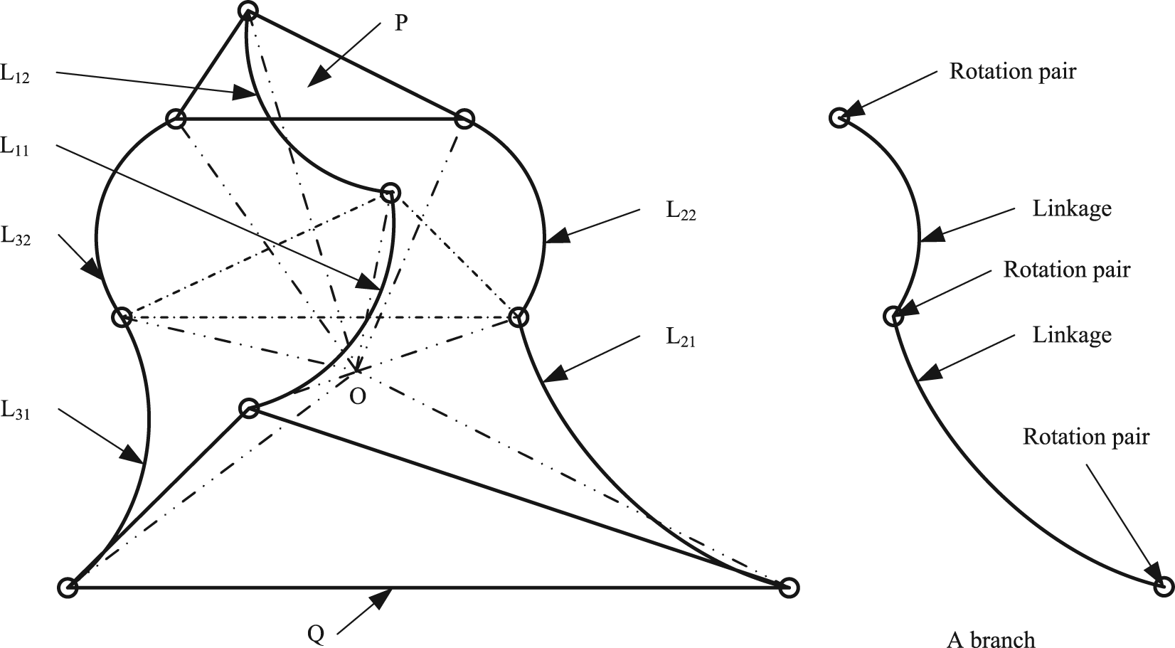
Schematic diagram of underactuated robot wrist.
The coordinate system of underactuated robot wrist
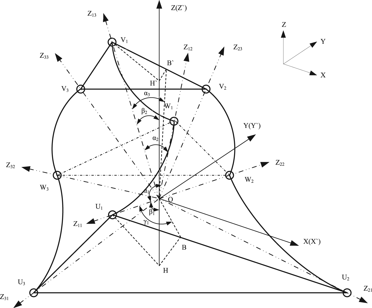
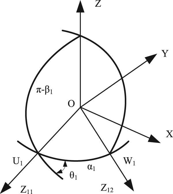
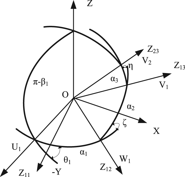
Just like some spherical 3-DOF parallel 3-RRR (Revolute-Revolute-Revolute) mechanism, 28 as shown in Figure 2, the coordinate system Oij-XijYijZij (i, j = 1, 2, 3) is built, in which i, j is the jth rotation joint in the ith branch. Since the axes of 3-DOF underactuated robot wrist joint are all focused to one point,13,29 the coordinate systems of each are selected at the same point, named point O.
The coordinate system of underactuated robot wrist.
The coordinate system of the jth rotation joint in the ith branch is set up as follows: when i = j = 1, the origin point of the coordinate system O-X11Y11Z11 is O. The Z11-axis is collinear with the axis of the joint outwards in the direction, and X11-axis in the normal direction is defined by Z11-axis and Z12-axis, as X11 = Z11 × Z12, and Y11-axis is determined by the right-hand rule as Y11 = ± X11 × Z11. Similarly, the coordinate system can be obtained in other joints. In order to analyse conveniently, the Xij-axis and Yij-axis are omitted in Figure 2.
The coordinate system O-XYZ is fixed on the base platform, whose original point is coincident with Oij-XijYijZij, with the Z-axis vertically upwards, X-axis in the normal direction defined by Z-axis and Z11-axis as X = Z × Z11, and Y11-axis determined by the right-hand rule, in Figure 2. The coordinate system O-X′Y′Z′ is fixed on mobile platform, whose origin point is coincident with Oij-XijYijZij, with the Z′-axis vertically upwards, X′-axis in the normal direction defined by Z′-axis and Z13-axis, and Y′-axis determined by the right-hand rule, in Figure 1. In the initial position, the fixed coordinate system O-XYZ is coincident with O-X′Y′Z′.
Basic parameters of underactuated robot wrist
Because of the symmetry of the structure, the wrist has four basic design parameters:
1. α1: the structure angle of the active link. It is the angle between Zi1-axis and Zi2-axis, i = 1, 2, 3.
2. α2: the structure angle of the passive link. It is the angle between Zi3-axis and Zi2-axis, i = 1, 2, 3.
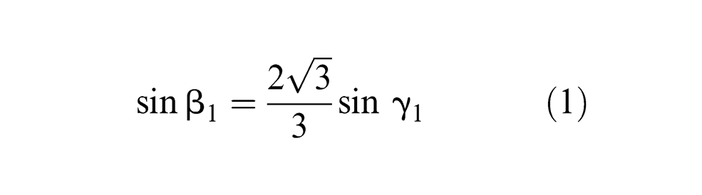
3. β1: the semi-cone angle formed by the base platform. It is the angle between Zi1-axis and Z-axis, as ∠U1OH; the cone formed by the three joint axes of base platform is shown in Figure 2. When β1 = 0, Zi1-axes are all collinear; when β1 = 90°, Zi1-axes are all coplanar; when β1 < 90°, the origin of spherical mechanism O is above the base platform; when β1 > 90°, the origin of spherical mechanism O is below the base platform, which is not a spherical mechanism. So as to form a spherical mechanism, the range of β1 is 0 ≤ β1 ≤ 90°. In Figure 2, B is the centre of the conical bottom edge as γ1 = ∠U1OB. According to the solid geometry, β1 and γ1 are related as follows
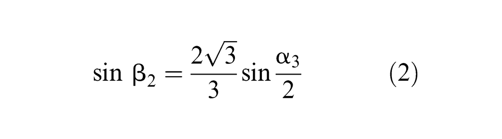
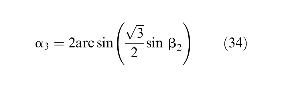
4. β2: the semi-cone angle formed by the mobile platform. It is the angle between Zi3-axis and Z′-axis; the range of β2 is 0 ≤ β2 ≤ 90°. α3 is the angle between Zi3-axis and Zj3-axis (i, j = 1, 2, 3, i ≠ j), named as angle of mobile platform angle cone. Similarly, the relationship between β2 and α3 is as follows
IKA of the underactuated robot wrist
The aim of IKA is to solve input angle of drive joints Φ1 and Φ2 with the known platform pose.
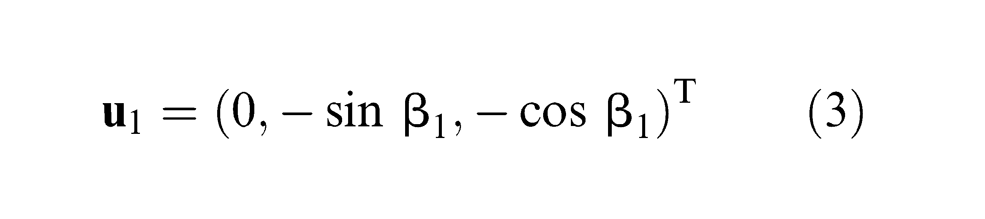
Unit vector of joint axis on base platform:
Based on the geometric relations shown in Figure 2
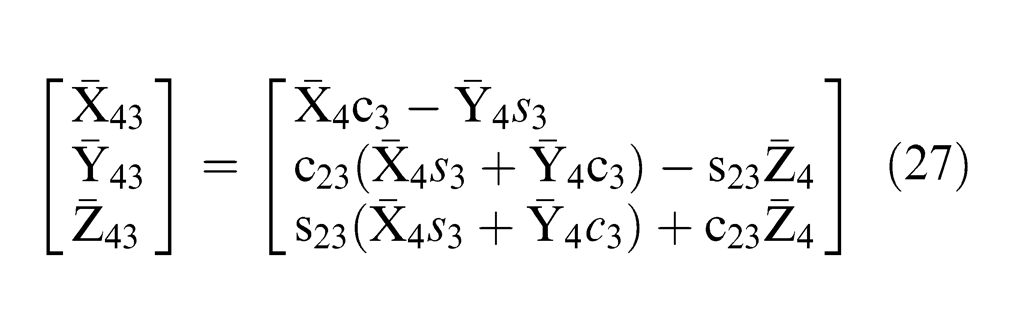
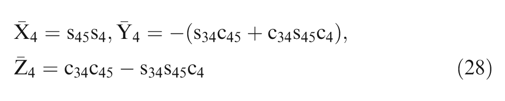
where
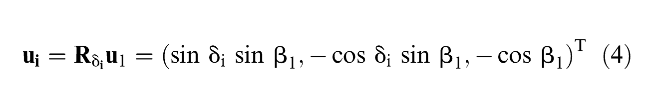
2. Unit vector of middle joint axis
The underactuated robot wrist is a spherical mechanism, whose unit vectors of three middle joint axes in each branch
1. The direction cosine of unit vector
In the fixed coordinate system O-XYZ, as shown in Figure 3, the angle between Z-axis and Z11-axis is (π-β1), and the angle between Z11-axis and Z12-axis is α1, and the exterior angle of Z11-axis is θ1. According to triangle sine formula, sine–cosine formula, and cosine formula in the spherical geometry theory, 30 the direction cosine of the unit vector for three middle joint axes can be derived as
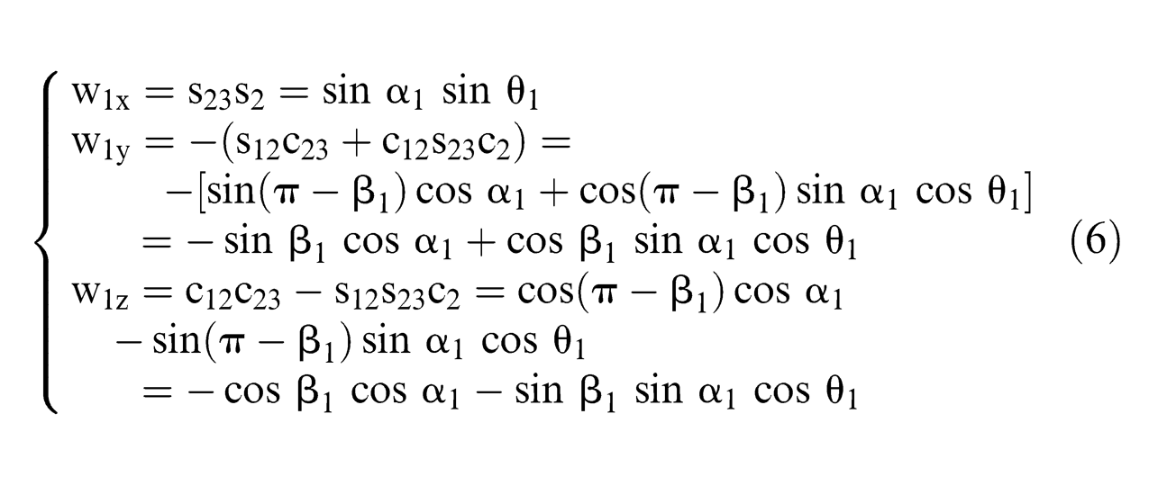
In formula (6), s23 and c23 represent the sine and cosine of the angle between Z11-axis and Z12-axis, respectively; s12 and c12 represent sine and cosine of the angle between Z-axis and Z11-axis, respectively; s2 and c2 represent sine and cosine of the exterior angle of Z-axis, respectively

The direction cosine of unit vector
2. The direction cosine of unit vector
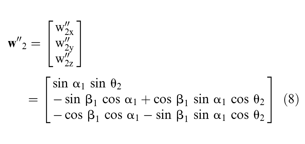
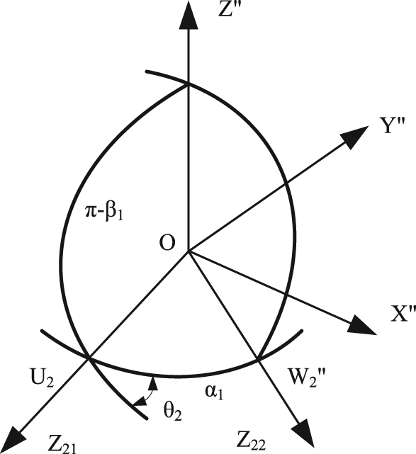
In another coordinate system O-X″Y″Z″, whose origin point is coincident with O-XYZ, Z″-axis is collinear with Z-axis and X″-axis in the normal direction defined by Z″-axis and Z21-axis as X″ = Z′ × Z21. In Figure 4, the angle between Z″-axis and Z21-axis is (π-β1), and the angle between Z21-axis and Z22-axis is α1, and the exterior angle of Z21-axis is θ2. According to triangle sine formula, sine–cosine, and cosine formula in the spherical geometry theory, the direction cosine of the three middle joint axes unit vector
The direction cosine of unit vector
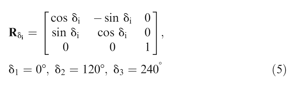
Due to the fixed coordinate system, O-XYZ can be rotated 120° around Z-axis, to coincide with the reference coordinate system O-X″Y″Z″
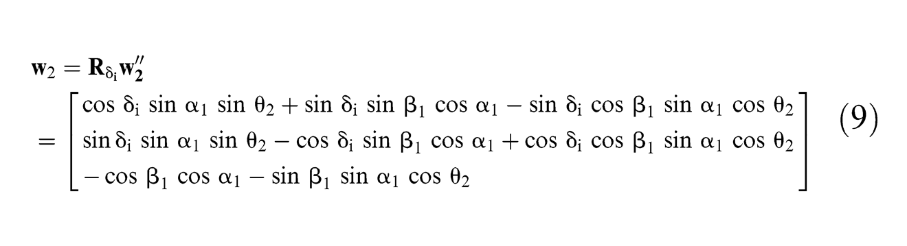
where δ2 = 120°.
3. The direction cosine of unit vector
Similarly, it can be obtained as

where δ3 = 240°.
In order to calculate conveniently, the direction cosine of middle joint axis unit vectors
where δ1 = 0°, δ2 = 120°, and δ3 = 240°.
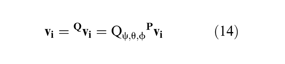
4. Euler angles of the mobile platform
The orientation of the mobile platform is expressed by Euler parameters. The coordinate system O-X0Y0Z0 is coincident with the coordinate system O-XYZ, as shown in Figure 5.
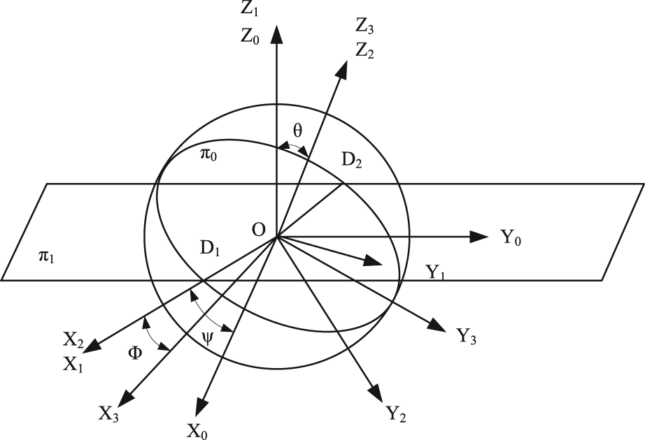
Euler angles of the mobile platform.
First, set up a plane π1 through the spherical centre O, which is parallel to the ground, crossing the spherical equatorial plane π0(⋄OX3Y3) with the line D1D2.The plane π1 rotates about the Z-axis of the coordinate system O-X0Y0Z0 by the angle ψ (the angle between X1-axis and OD1), reaching the position of O-X1Y1Z1; then rotates about X1-axis by the angle θ, where axis Y2∈π0, reaching the position of O-X2Y2Z2; and in the plane π0, rotates about Z2-axis by the angle Φ, reaching the position O-X3Y3Z3, which is coincident with O-X′Y′Z′. Thus, ψ, θ, and Φ are the Euler angles of the mobile platform, where precession angle ψ = ∠XOD1, nutation angle θ = ∠ZOZ3, and self-rotation angle Φ = ∠D1OX3, which can only determine the orientation at an arbitrary time in the inertial coordinate system.
The conversion process is as follows
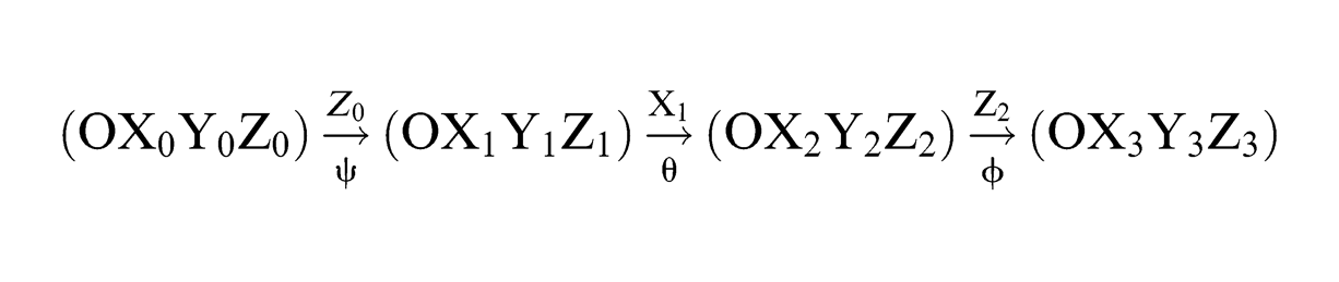
Thus, the transformation matrix between the coordinate system O-X′Y′Z′ and O-XYZ
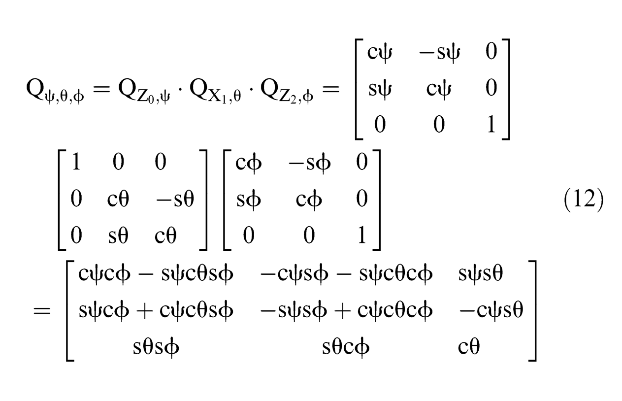
and cψ = cosψ and sψ = sinψ.
5.
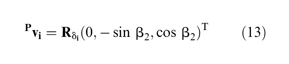
The direction cosine of the joint axis unit vector
The direction cosine of mobile platform joint axis unit vector
Based on the theory of spherical geometry, 30 it can be easily obtained as
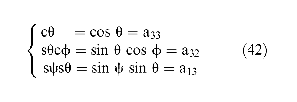
From formula (14), with the known platform pose ψ, θ, and Φ, the demand driven source input angles
6. Inverse kinematics
Since the angle between a branch in the middle joint and the joint of the mobile platform is fixed as α2

In order to calculate conveniently, make

Formulas (11) and (14) are introduced into formula (15)
simplified as

in which
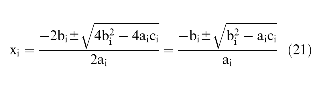
Given
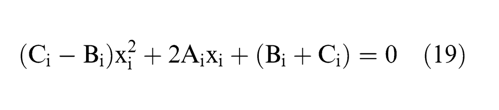
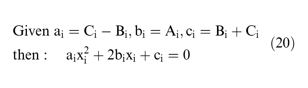
solving quadratics
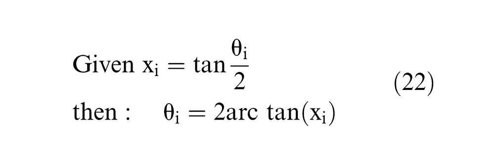
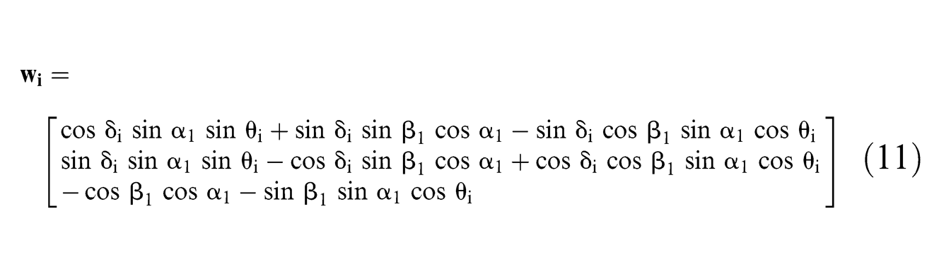
The result of θi is the exterior angle of Zi1-axis, not Φi in IKA. The input angles of the motor are Φ1 and Φ2; Φ3 is the angle of no driving source branch detected by the angle sensor. According to the right-hand rule, the counterclockwise rotation about Zi1-axis is positive, and the clockwise rotation is negative. The relationship between Φi and θi

θ0 is the value of θi at the initial position (ψ = 0, θ = 0, and Φ = 0).
The principles of selecting the only right group joint angles among eight solutions of IKA are as follows:
To satisfy the range of each joint angle in the mechanical wrist.
The angle is unlikely to occur to a large beating since the continuity of the movement.
The pose solution of the mechanical wrist is determined by the experiment, which must be also validated by the inverse kinematics analysis to ensure that the robot is not in a singular position.
According to this principle, the most appropriate group of the inverse kinematic solution is selected.
FKA of the underactuated wrist
The aim of FKA is to find the moving platform pose ψ, θ, and Φ, with two known input angles of drive joints, Φ1 and Φ2, and the angle of no driving source branch detected by angle sensor, Φ3. Based on the relationship between Φi and θi and the relationship between
The following method solves the forward kinematics by using θi to solve
The direction cosine of joint axis unit vector
(a) The direction cosine of joint axis unit vector
In fixed coordinate system O-XYZ, as shown in Figure 6, the angle between Z-axis and Z11-axis is (π-β1), the angle between Z11-axis and Z12-axis is α1, the angle between Z12-axis and Z13-axis is α2, the exterior angle of Z11-axis is θ1, and the exterior angle of Z12-axis is ζ. According to spherical quadrilateral sine formula, sine–cosine formula, and cosine formula in the theory of spherical geometry, the direction cosine of the three joint axes unit vector v1x, v1y, and v1z can be obtained as
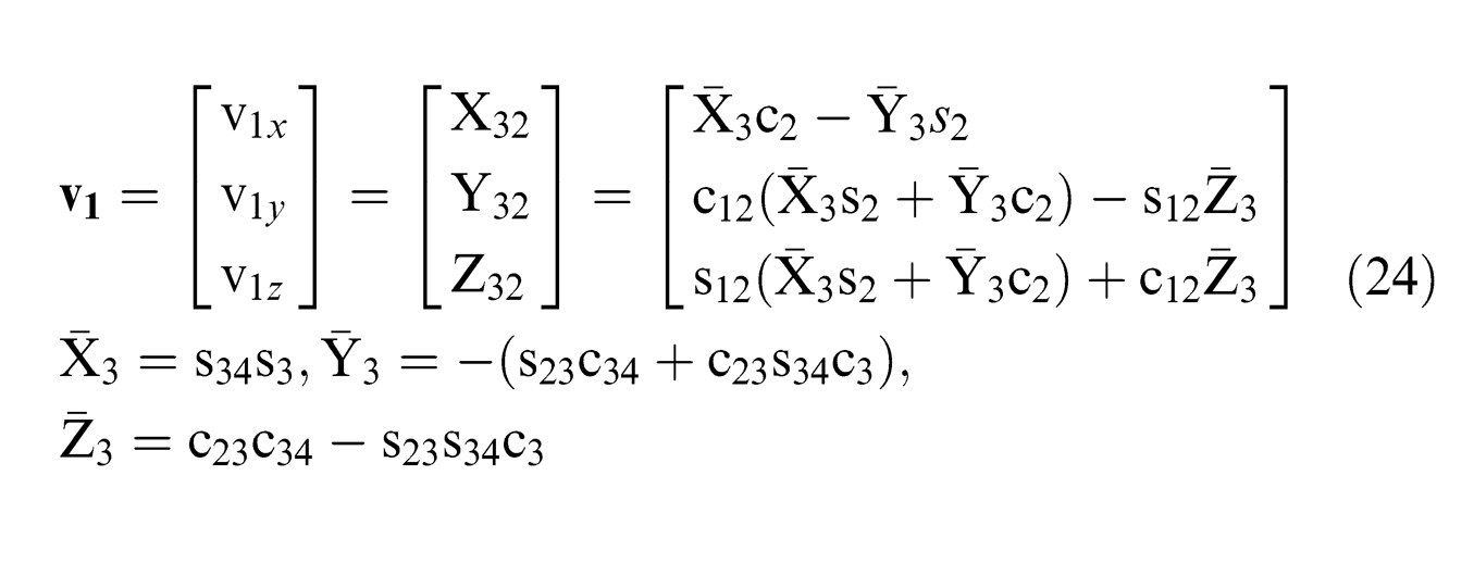
and
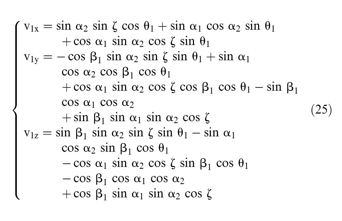
where s2 and c2 represent the sine and cosine of the exterior angle θ1, respectively; s3 and c3 represent the sine and cosine of the exterior angle ζ, respectively; s12 and c12 represent the sine and cosine of the angle (π-β1) between Z-axis and Z11-axis, respectively; s23 and c23 represent the sine and cosine of the angle α1 between Z11-axis and Z12-axis, respectively; s34 and c34 represent the sine and cosine of the angle α2 between Z12-axis and Z13-axis, respectively.
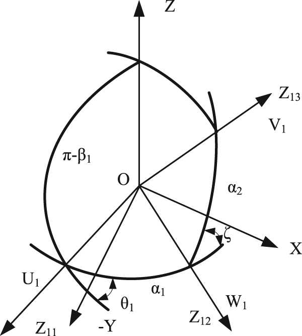
Spherical quadrilateral of joint axis unit vector
(b) The direction cosine of joint axis unit vector
In fixed coordinate system O-XYZ, spherical pentagon is shown in Figure 7. The angle between Z-axis and Z11-axis is (π-β1), the angle between Z11-axis and Z12-axis is α1, the angle between Z12-axis and Z13-axis is α2, the angle between Z13-axis and Z23-axis is α3, the exterior angle of Z11-axis is θ1, the exterior angle of Z12-axis is ζ, and the exterior angle of Z13-axis is η. According to spherical quadrilateral sine formula, sine–cosine formula, and cosine formula in the theory of spherical geometry, the direction cosine of the three joint axes unit vector v2x, v2y, and v2z can be obtained as
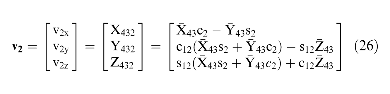
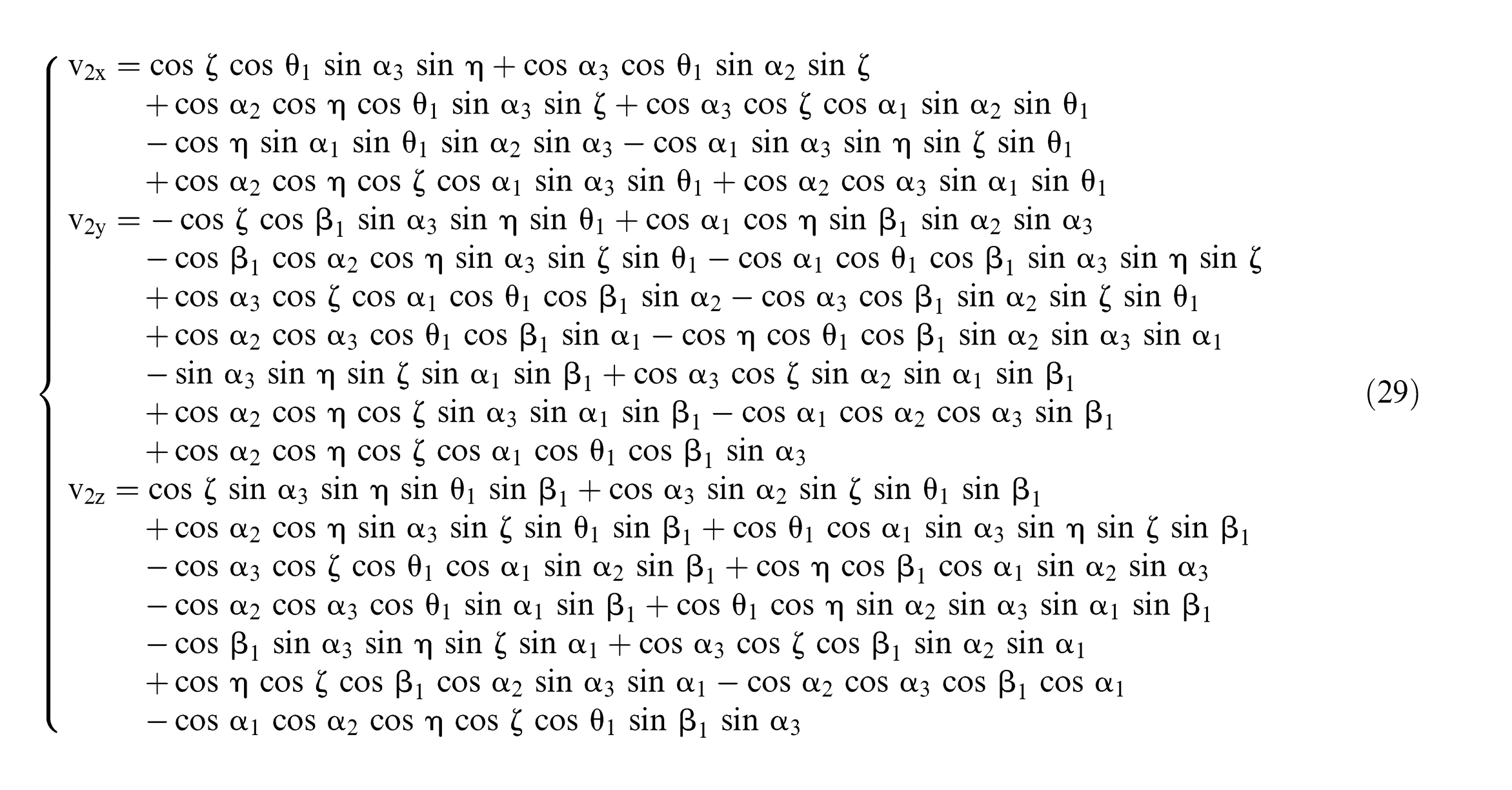
where s2 and c2 represent the sine and cosine of the exterior angle θ1, respectively; s3 and c3 represent the sine and cosine of the exterior angle ζ, respectively; s12 and c12 represent the sine and cosine of the angle (π-β1) between Z-axis and Z11-axis, respectively; s23 and c23 represent the sine and cosine of the angle α1 between Z11-axis and Z12-axis, respectively; s34 and c34 represent the sine and cosine of the angle α2 between Z12-axis and Z13-axis, respectively; s45 and c45 represent the sine and cosine of the angle α3 between Z13-axis and Z23-axis, respectively.
Spherical pentagon of joint axis unit vector
(c) The direction cosine of joint axis unit vector
Similarly, a spherical pentagon is shown in Figure 8. It is obvious to obtain the direction cosine by replacing η with η′ (formula (29)) because of the similarity of the direction cosine of
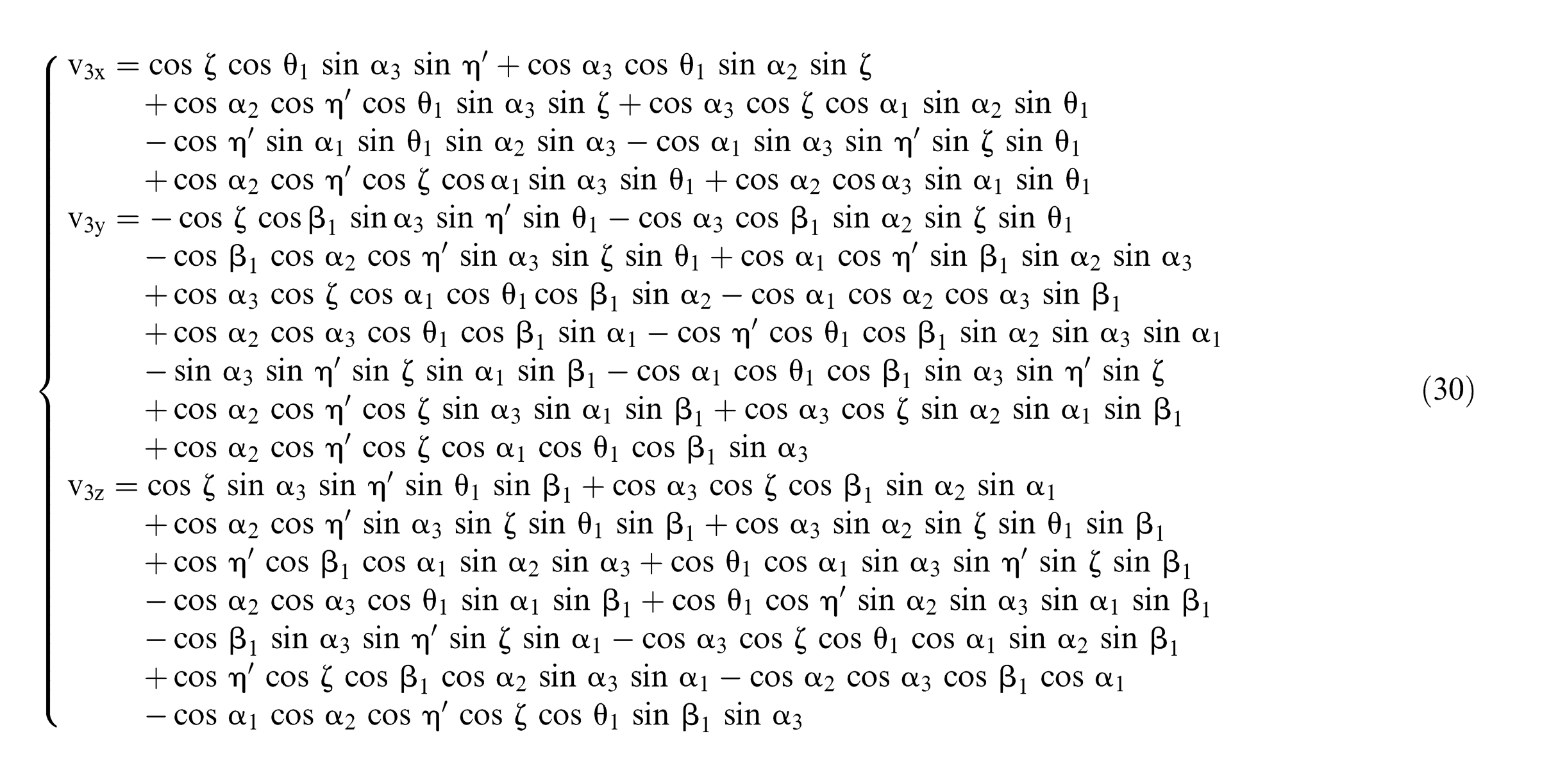

Spherical pentagon of joint axis unit vector
The spherical triangle is shown in Figure 9, the angle between Z33-axis and Z13-axis is α3, the angle between Z13-axis and Z23-axis is α3, the angle between Z33-axis and Z23-axis is α3, and the exterior angle of Z13-axis is µ.
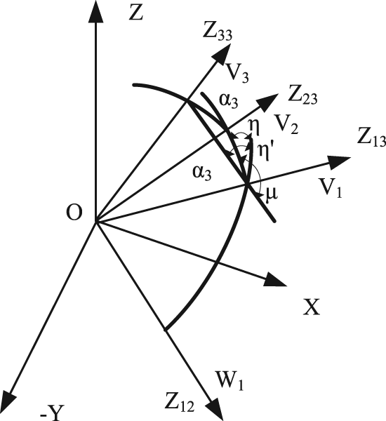
Spherical triangle.
The relationship between η′ and η can be obtained from Figure 9
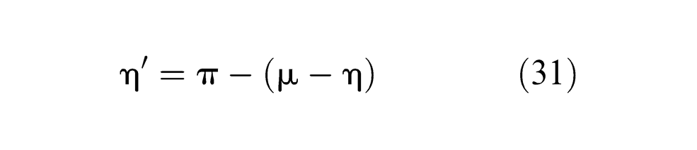
Based on the theory of spherical geometry, it can be easily obtained as
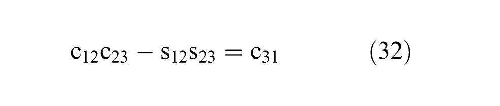
Given
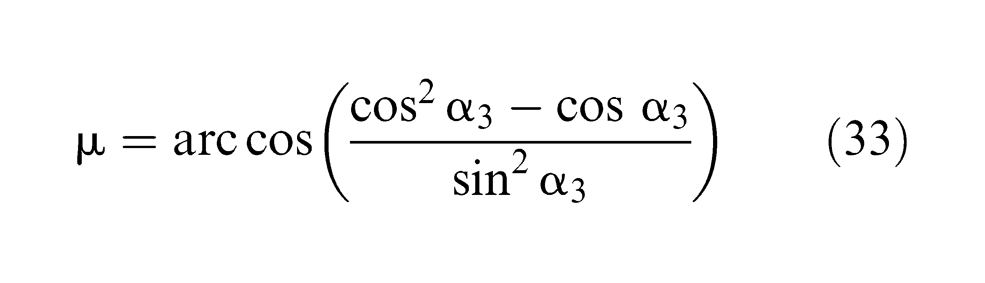
It is shown from formula (1) that
The direction cosine of joint axis unit vector
2. FKA
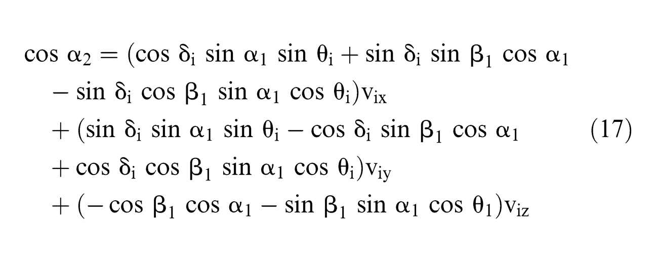
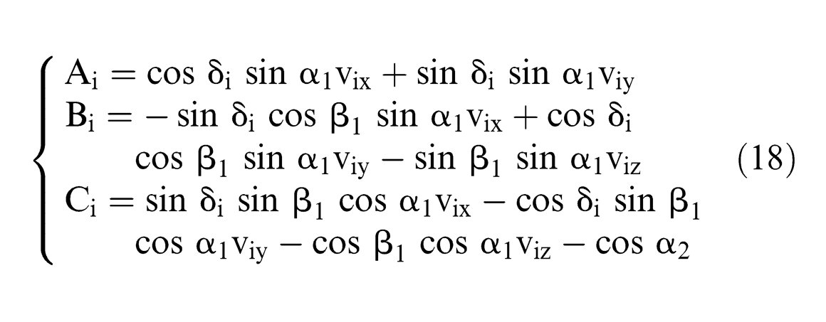
Since the angle between a branch in the middle joint and the joint of the mobile platform is fixed as α2

Formulas (10), (11), (20), and (21) introduced into formula (35) yield
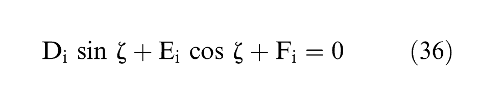
Di, Ei, and Fi are formulas expressed by θ1, θ2, θ3, and η; the following is the solution of η. From formula (36), the following can be obtained
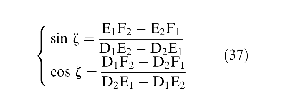
According to the identity
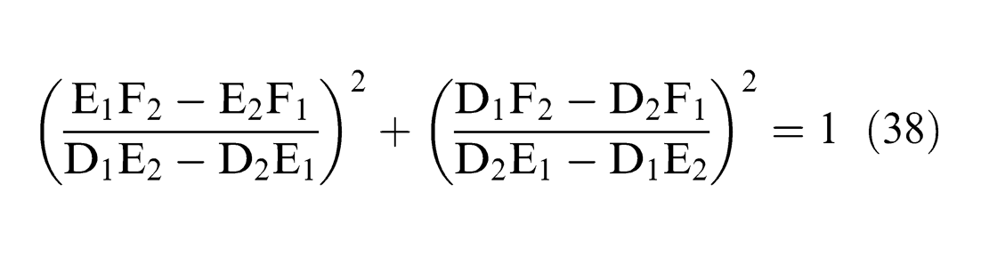
when D2E1 − D1E2 ≠ 0, formula (38) is multiplied by (D2E1 − D1E2) 2 on both sides
If parameters θ1, θ2, and θ3 are known in the formula above, η is the only unknown parameter. For convenient solution, given
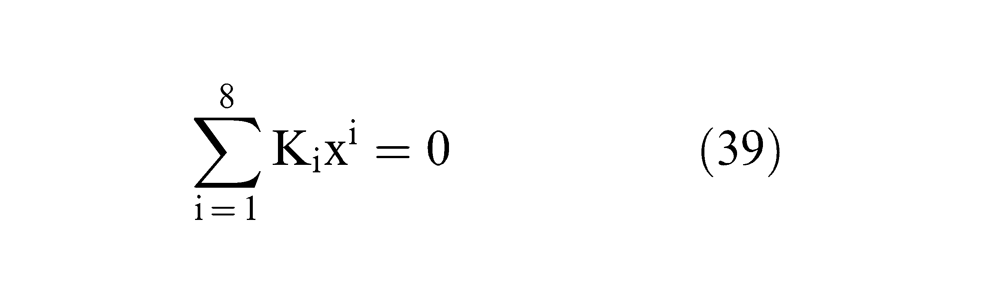
and Ki is a formula about θ1, θ2, and θ3.
When the values of θ1, θ2, and θ3 are known, x can be obtained easily, and then, η and ζ from formula (37). Then
Based on formula (14)
And
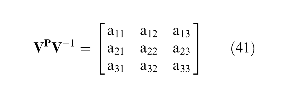
Compared with formula (12)
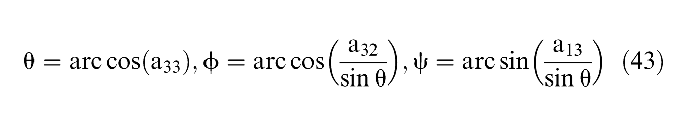
Then, ψ, θ, and Φ can be obtained as follows
Due to the various solutions to underactuated wrist FKA, it can refer to the select principle of the IKA. In order to make it clear, the solution of FKA is shown in Figure 10. As the kinematic model is complex, discretization method is applied to the forward kinematic solution. In this way, select a group of θ1, θ2, and θ3, introduce into above formulas, and get the Euler angles ψ, θ, and Φ using MATLAB.
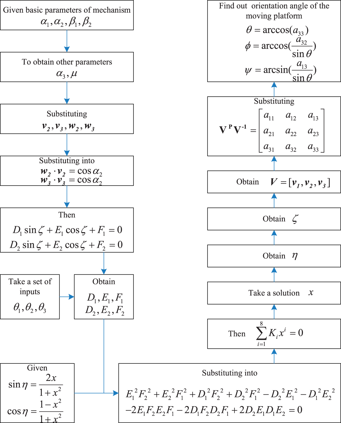
The solving process of the forward kinematic analysis.
Kinematics numerical simulation based on virtual prototyping
The process of kinematics simulation
After three-dimensional (3D) model of the robot wrist was established, the simplified model as a Parasolid file was imported into ADAMS for further process.
1. Set the coordinate system
As the moving platform direction angle is represented by the Euler parameters, in order to study the relationship between the input angle and the direction angle of the moving platform, the spherical coordinate system was rotated as the order 313, whose centre coincides with the origin of the coordinate system of the body.
2. Set the gravity direction
Confirm the gravity settings as Y-axis direction.
3. Change the part name and colour
Change the colour and the name of each part, and also the transparency to facilitate observation and selection, as there are still a lot of parts.
4. Specify the part material
The material of each part must be specified. According to the material and geometry, the mass and moment of inertia of the main components are calculated. All the parts of the robot wrist are designated as 45 steel (density 7801.0 kg/m3).
5. Add constraints and kinematic pairs
Establish mutual relations among all the parts according to their motion relationships. A fixed connection is used between two relatively static parts, such as fixed platforms and ground fixed, while a rotate connection is used between links. There are also some friction constraints in the robot wrist.
6. Add driving movement
Finally, specify the drive mode of the joints to achieve a predetermined motion. Add drive (Rotational Joint Motion) to revolution joint and select the motion parameters from the menu Function (time). Motion function is mainly used for controlling joint movement with function STEP, which can not only be a design function but also be a runtime function. When it is used as a runtime function, the format is
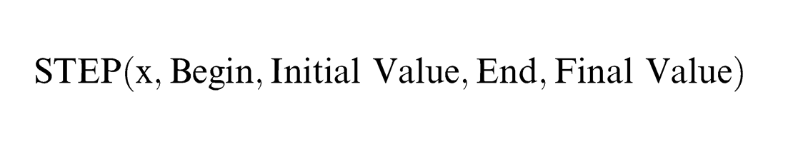
which is a step function with a cubic polynomial structure, and x is the autonomous variable that decides the start (Begin, Initial Value) and the end (End, Final Value). The value is initial value when the time’s range is from 0 to Begin and then increases (or decreases) to Final Value by the time END.
Each input revolution joint driving function is as follows:
Motion 1: step (time, 0.0, 0.0, 5, −20d)
Motion 2: step (time, 0.0, 0.0, 5, −15d)
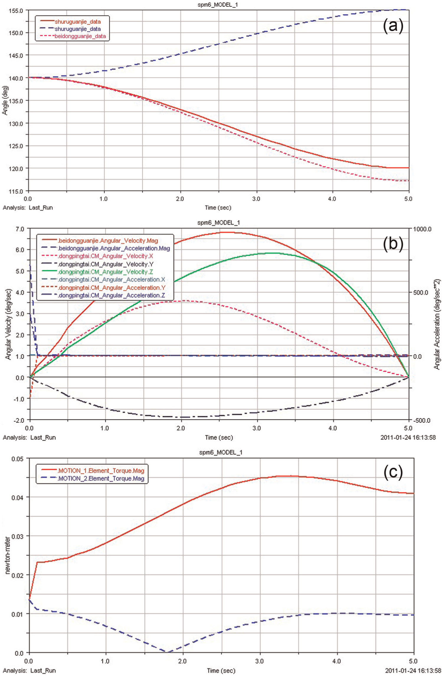
The initial position of the input joint angle is 140°. The drive function Motion 1 represents that one of the inputs is to rotate 20° at 0–5 s from the initial position to reach angle 120°. The drive function Motion 2 represents that another input is to rotate 15° at 0–5 s from the initial position to reach the angle 125°.
After these settings, virtual prototyping–based model was built up in ADAMS in Figure 11. In the simulation process, the base platform is fixed on the ground, while the motor is fixed on the base platform, so the motor model has no effect on simulation. Motors and connecting shaft between the joints are omitted in this virtual prototyping.
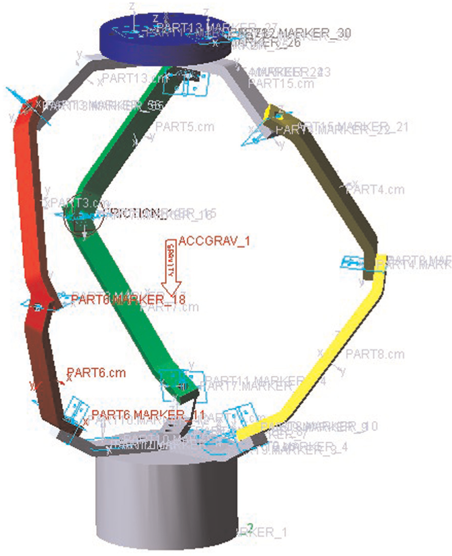
Virtual prototyping–based underactuated mechanism.
Analysis of simulation results
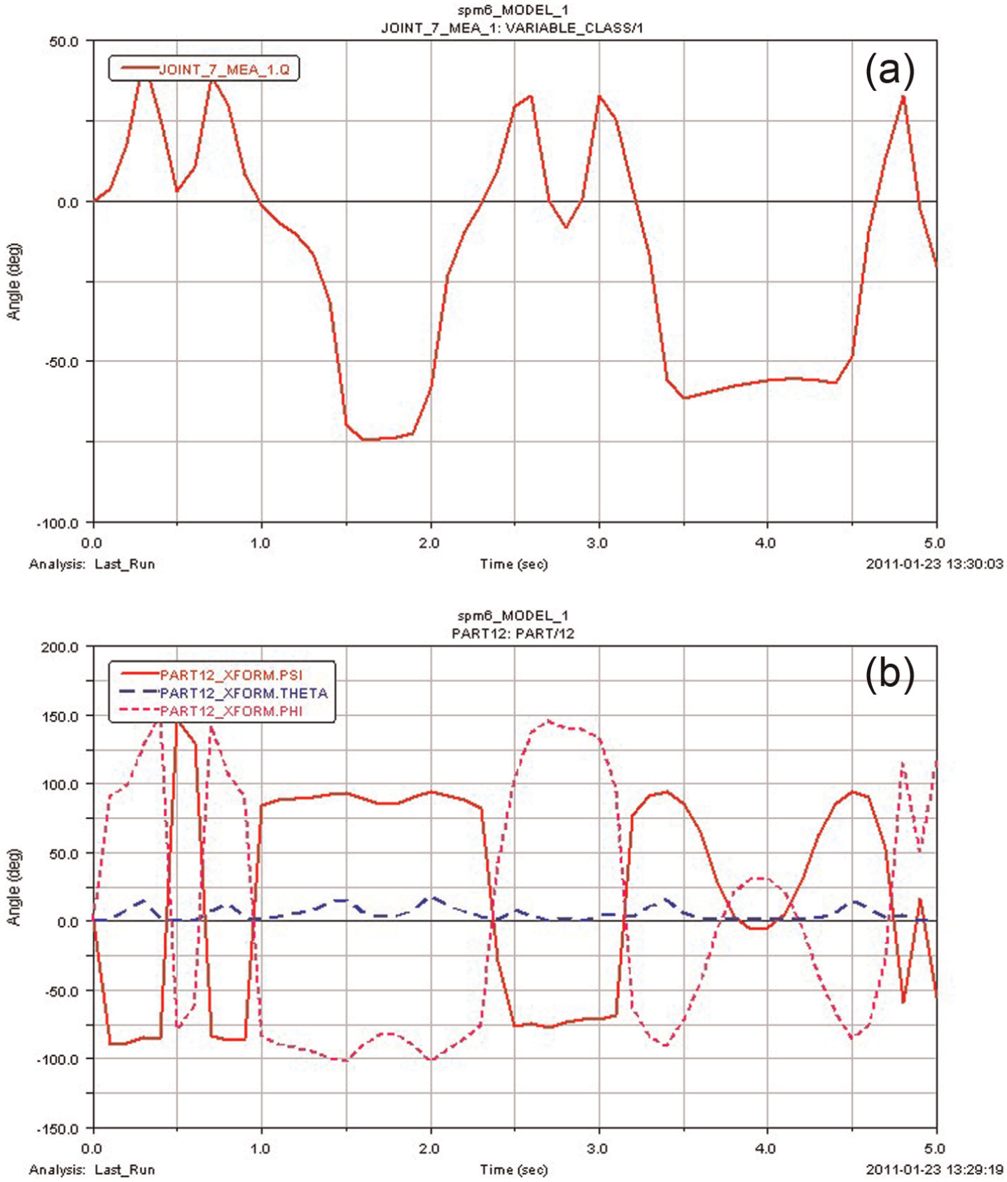
With all the above settings, the simulation can start. The simulation time is set to t = 5 s, and the simulation step is set to steps = 50, which can be modified to compare the change to kinetic parameters of the robot wrist. The curves of joint angular velocity, angular acceleration, and joint torque of each joint angle are as shown in Figure 12.
Curves of two drive joint angles.
Underactuated wrist movement with mechanical friction
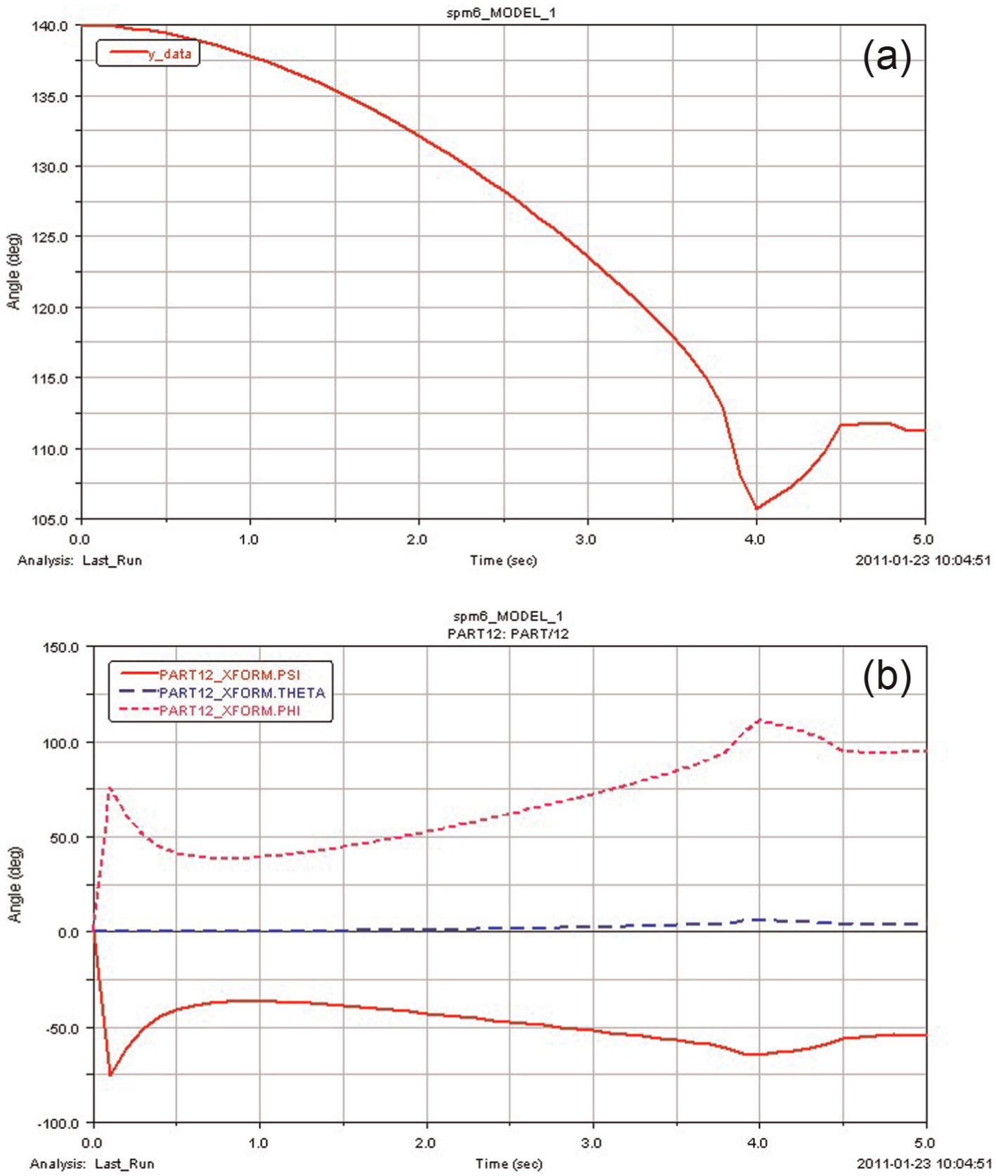
In order to study the mechanical friction s impact on the movement, a friction-free state was studied with the results of curves of passive joint angle and mobile platform direction angle, shown in Figure 13(a) and (b).
(a) The vibration of passive angle and (b) the vibration of mobile platform direction angle.
From these figures, passive joint angles can be reciprocating vibration, and the direction angle of the mobile platform also can be reciprocating vibration. There will be a certain degree of vibration in passive joint with no drive.
For the realistic physical model, the joints cannot be without friction. So, set the kinetic friction factor of the revolution joint between driving bar and following bar of the passive branch as 0.1, and the static friction factor as 0.5. The curves of passive joint angle and mobile platform direction angle are as shown in Figure 14.
(a) The vibration of passive angle and (b) the vibration of mobile platform direction angle.
Comparing Figure 13 with Figure 14, the passive joint angle and the direction angle of mobile platform changed steadily.
The angular velocity and angular acceleration changes of the two drive joints and passive joint are shown in Figure 15(a), while the angular velocity and angular acceleration changes of the mobile platform are shown in Figure 15(b).
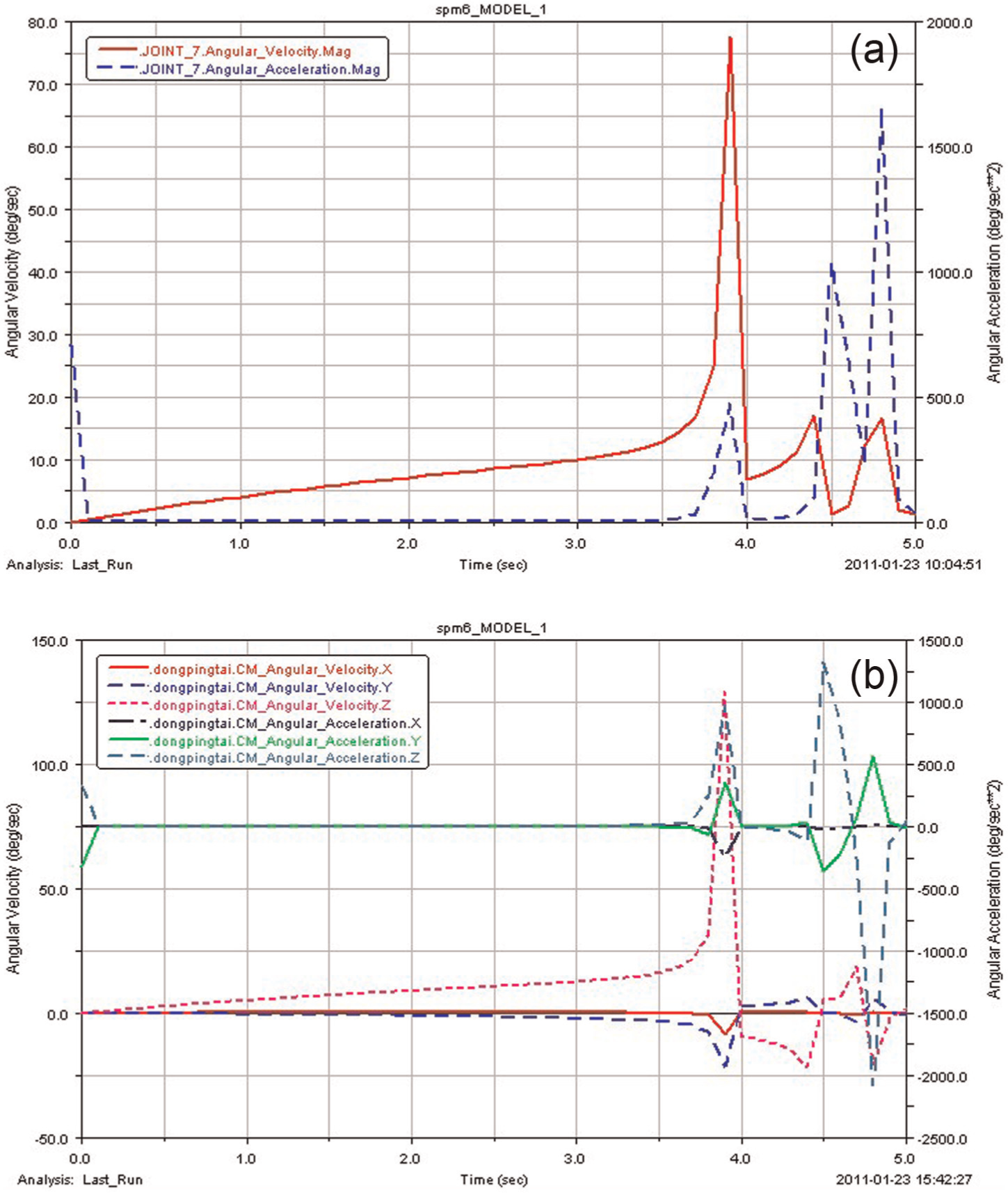
(a) Angular velocity and angular acceleration changes of the two drive joints and one passive joint and (b) angular velocity and angular acceleration changes of the mobile platform.
In Figure 15, the angular velocity and angular acceleration of the two drive joints and passive joint and angular velocity and angular acceleration changes of the mobile platform, with vibration at 4–5 s without the drive, are shown.
Underactuated wrist movement with different driving speeds
In comparison, the end time of the two drive functions in ADAMS was changed, which is t = 20 s from the former value of t = 5 s as follows:
Motion 1: step (time, 0.0, 0.0, 20, −20d)
Motion 2: step (time, 0.0, 0.0, 20, −15d)
While the simulation time is set as 20 s with the same other conditions, simulate again and observe the results.
Comparing Figure 16(c) and (d) with Figure 15(a) and (b), because of the ever longer time with the same angle range, the angular velocity and angular acceleration of the two drive joints and passive joint are decreased, of which the vibration is also decreased at the end time. The angular velocity and angular acceleration of the mobile platform are also decreased. With the decreased vibration at the ending time, it shows that the different drive speeds have influence on the vibration strength of mobile platform and following bar.
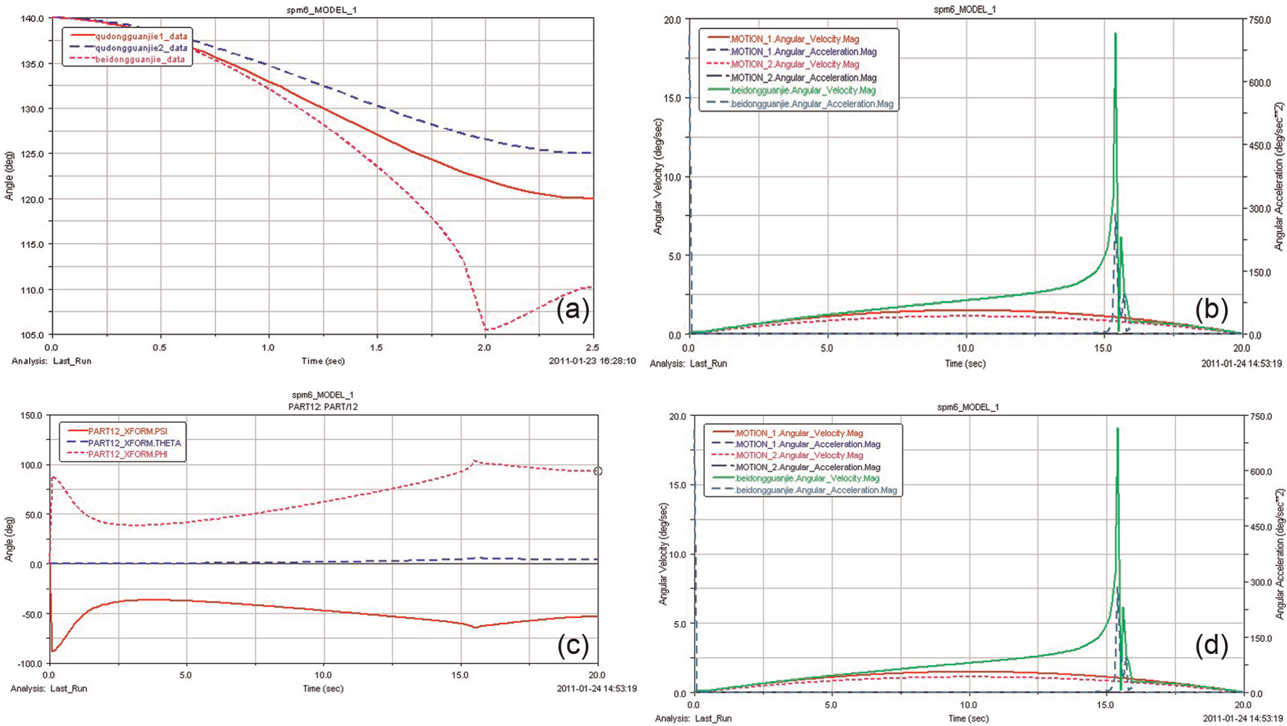
(a) Angular changes of the two drive joints and one passive joint when t = 20 s, (b) angular velocity and angular acceleration changes of the two drive joints and one passive joint when t = 20 s, (c) changes of mobile platform direction angle when t = 20 s, and (d) angular velocity and angular acceleration changes of the mobile platform when t = 20 s.
Comparing Figure 16(d) with Figure 14(b), the values of the mobile platform direction angle at different simulation times t = 5 s and t = 20 s are shown in Table 1.
Mobile platform direction angle when t = 5 s and 20 s.
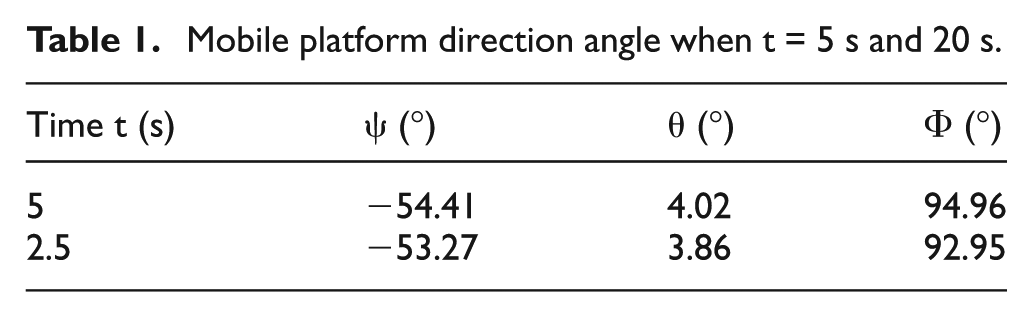
In Table 1, the value of mobile platform direction angle is smaller when drive function with time t = 20 s, which shows that the smaller the drive angle, the smaller the mobile platform direction angle.
Underactuated wrist movement with different driving directions
For comparison, change the drive direction of the underactuated wrist in ADAMS, Motion 2 is in the opposite direction as follows
Motion 1: step (time, 0.0, 0.0, 5, −20d)
Motion 2: step (time, 0.0, 0.0, 5, 15d)
The other working conditions are the same as previously, and re-simulate the model, and then the results can be observed. Comparing Figure 17(b) and (c) with Figure 15(a) and (b), the angular velocity and angular acceleration of the passive joint and the mobile platform are always stable, with no cusp phenomenon.
(a) Angular changes of the two drive joints and passive joint with inverse direction of Motion 2, (b) angular velocity and angular acceleration changes of passive joint and mobile platform with the inverse direction of Motion 2, and (c) torque changes of the two drive joints with the inverse direction of Motion 2.
The torque changes of the two drive joints are also stable at 4–5 s without the cusp phenomenon. It is shown that the process of simulation is stable all time, and the drive direction has great influence on the movement of the robot wrist.
Verification of FKA
Based on the FKA, the moving platform posture can be obtained with known input angle of drive source, which is solved by the above method shown in Figure 11. The basic initial parameters of the robot wrist are α1 = 60°, α2 = 60°, β1 = 30°, and β1 = 43.89°; the direction angle of the mobile platform is calculated by the method shown in Figure 11, and the results are shown in Table 2. θ1, θ2, and θ3 represent the exterior angles of the three input angles, respectively. Based on Figures 12 and 14(a), θ1, θ2, and θ3 at certain moments of t = 0 s, t = 0.1 s, t = 1 s, t = 2 s, t = 3 s, t = 4 s, and t = 5 s are picked to compare the results calculated by MATLAB.
η (°), ζ (°), ψ (°), θ (°), and Φ (°) with the change of θ1, θ2, and θ3.
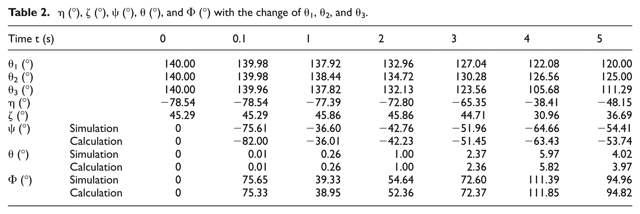
For instance, the values of θ1 are 140.00°, 139.98°, 137.92°, 132.96°, 127.04°, 122.08°, and 120.00°; θ2 are 140.00°, 139.98°, 38.44°, 134.72°, 130.28°, 126.56°, and 125.00°; and θ3 are 140.00°, 139.96°, 137.82°, 132.13°, 123.56°, 105.68°, and 111.29° at 0, 0.1, 1, 2, 3, 4, and 5 s based on the above FKA method, and the values for ψ at 0, 0.1, 1, 2, 3, 4, and 5 s are calculated as −82.00°, −36.01°, −42.23°, −51.45°, −63.43°, and −53.74°, while the values of the simulation are 0°, −75.61°, −36.60°, −42.76°, −51.96°, −64.66°, and −54.41°, respectively.
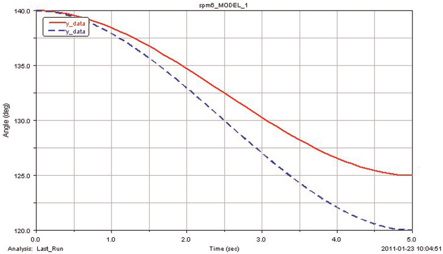
The values of ψ, θ, and Φ are introduced into ADAMS to compare with the simulation results shown as follows. The solid line indicates the direction angle of the mobile platform theoretically, while the dotted line is the curve simulation in ADAMS.
From Figure 18, it can be observed that theoretical and simulated direction angles of the mobile platform are close to each other, showing the validity of the above theoretical analysis. Due to the rounding error in the calculation process, or the vibration of the motor in the initial state, or some fractions, the input angles in the table by methods of simulation and calculation are not exactly the same.
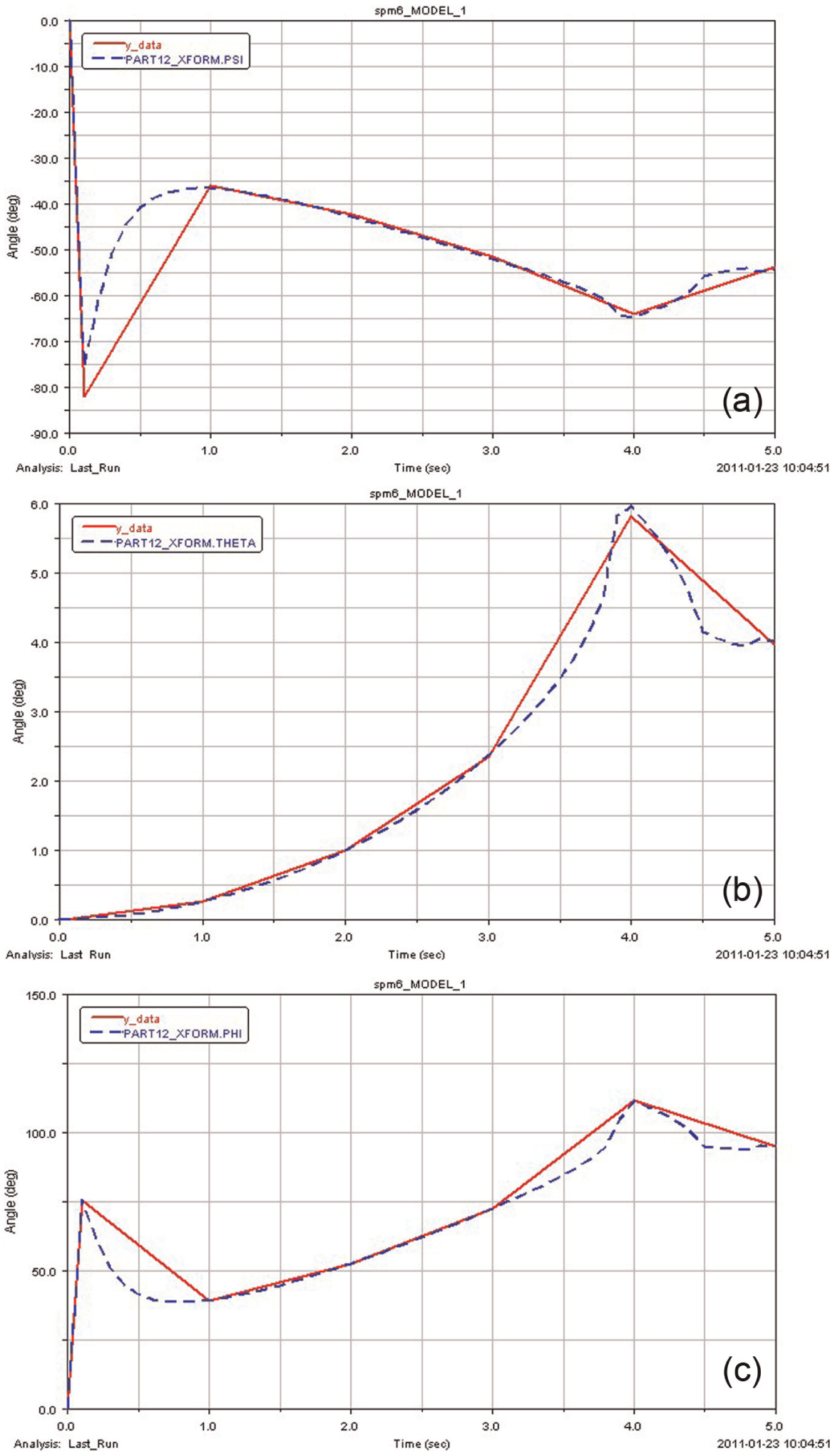
(a) The theoretical and simulated direction angle ψ (°) of the mobile platform, (b) the theoretical and simulated direction angle θ (°) of the mobile platform, and (c) the theoretical and simulated direction angle Φ (°) of the mobile platform.
Verification of IKA
Based on the theory of IKA, the drive angle with the known platform pose can be obtained.
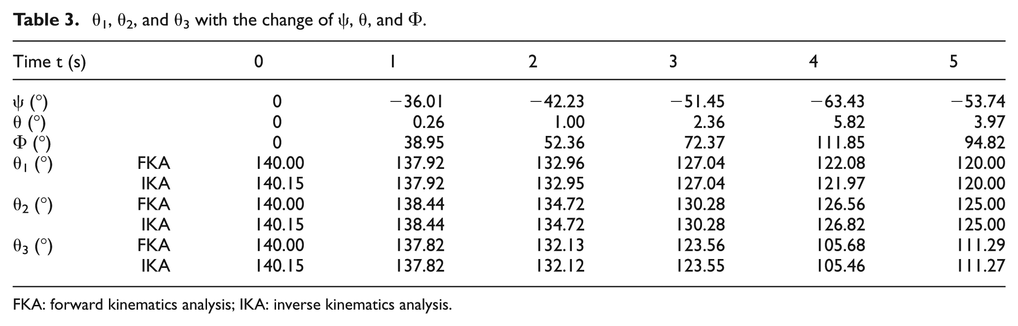
As the mapping between the direction angle of the mobile platform and the input joint angle is known from section ‘Verification of FKA’, each group of mobile platform direction angle, from Table 2, is introduced into the formulas of the IKA yielding the input angels to compare with the angles of the same group.
The results of inverse kinematic by MATLAB are shown in Table 3. For instance, the values of ψ at 0, 0.1, 1, 2, 3, 4, and 5 s are 0°, −36.01°, −42.23°, 51.45°, −63.43°, and −53.74°, respectively, and the values of θ are 0°, 0.26°, 1.00°, 2.36°, 5.82°, and 3.97°, and the values of Φ are 0°, 38.95°, 52.36°, 72.37°, 111.85°, and 94.82°, respectively. θ1, θ2, and θ3 at certain moments of t = 0 s, t = 1 s, t = 2 s, t = 3 s, t = 4 s, and t = 5 s are calculated by introducing ψ, θ, and Φ into formulas (15)–(24).
θ1, θ2, and θ3 with the change of ψ, θ, and Φ.
FKA: forward kinematics analysis; IKA: inverse kinematics analysis.
In Table 3, the theoretical and simulated input angles are very close to each other, showing the validity of the theoretical analysis. Due to the rounding error in the calculation process, input angles in the table by methods of FKA and IKA are not exactly the same.
Conclusion
This article proposed kinematics analysis and numerical simulation of a novel underactuated robot wrist. After a novel understated robot wrist was proposed, the IKA and FKA of the underactuated robot wrist were proposed in detail. Then, the kinematics numerical simulation based on virtual prototyping was also put forward. After the underactuated wrist movements with mechanical frictions, with different driving speeds, and with different driving directions were discussed in detail, the FKA and IKA were verified, which are used to demonstrate the proposed methodology.
Footnotes
Appendix 1
Declaration of conflicting interests
The authors declare that there is no conflict of interest.
Funding
The work was supported by National Natural Science Foundation of China (no. 51305249) and Shanghai Science and Technology Commission Project (no. 12dz1125702).