
Abstract
For the purpose of obtaining high-precision in stereo vision calibration, a large-size precise calibration target, which can cover more than half of the field of view is vital. However, large-scale calibration targets are very difficult to fabricate. Based on the idea of error tracing, a high-precision calibration method for vision system with large field of view by constructing a virtual 3-D calibration target with a laser tracker was proposed in this article. A virtual 3-D calibration target that covers the whole measurement space can be established flexibly and the measurement precision of the vision system can be traceable to the laser tracker. First, virtual 3-D targets by calculating rigid body transformation with unit quaternion method were constructed. Then, the high-order distortion camera model was taken into consideration. Besides, the calibration parameters were solved with Levenberg–Marquardt optimization algorithm. In the experiment, a binocular stereo vision system with the field of view of 4 × 3 × 2 m3 was built for verifying the validity and precision of the proposed calibration method. It is measured that the accuracy with the proposed method can be greatly improved comparing with traditional plane calibration method. The method can be widely used in industrial applications, such as in the field of calibrating large-scale vision-based coordinate metrology, and six-degrees of freedom pose tracking system for dimensional measurement of workpiece, as well as robotics geometrical accuracy detection and compensation.
Introduction
Nowadays, stereo vision system is widely used in the fields of precision industrial metrology and aerospace, 1 due to its characteristics of noncontact, portability, low cost, and informative. With the rapid development of industrial technology, more and more applications such as robotics 2 –4 and industrial automation demand a stereo vision system, which is accurate with a large measurement volume.
Measurement precision is a fundamental performance in a vision metrology system, which is mainly restricted by following factors such as quality of source images, camera calibration method, accuracy of image characteristics extraction, object size and measurement distance, relative pose among cameras, random noise, and so on. 5 Among them, both calibration of camera parameter and image characteristics extraction are fundamental factors affecting measurement precision. 6,7 At present, image characteristics extraction algorithm is already relatively mature with good performance. Therefore, when the configuration of the vision system is given, measurement precision of a vision system is mainly determined by camera calibration process. Besides, for the purpose of obtaining high-precision calibration in large-scale vision metrology system, a large-size precise calibration target, which can cover more than half of the field of view (FOV), is vital.
The traditional camera calibration is performed by taking images of a 3-D calibration target with known and accurate geometry. 8,9 The calibration can be done with very high accuracy. However, it is very difficult and expensive to fabricate large-scale 3-D calibration targets. Camera calibration method with planar pattern proposed by Zhang 6 is widely used in the field of computer vision and has good performance and efficiency. 10 But this method has the limitation on the preparation of large-scale calibration pattern. A large-size calibration target can be made by printing process, which cannot guarantee the dimensional accuracy and flatness of the planar pattern. In this case, the calibration result may be poor. Although ceramic lithography calibration plate can be very accurate, it is very difficult to fabricate large-size one at reasonable cost. Faugeras et al. 11 originally proposed the self-camera calibration method without requiring calibrating targets. Constraints of parameters of cameras were used to calibrating stereo vision sensors. However, it is tough to obtain high-accuracy.
As a result, the stereo vision systems presently have a high precision for the measurement of small-size objects. 12 However, for the large-size objects, it often failed to balance measurement range, accuracy, and efficiency in the application of large-scale metrology since the measurement environment is difficult to control, large-scale calibration target is difficult to fabricate, and the calibration process is complicated. 13,14
To overcome the low-accuracy shortcomings of current vision system with large FOV, a number of researches have been contributed to this field. Zou et al. 15,16 proposed a camera calibration method, in which a laser pointer was installed on a calibration target. Large-scale global calibration could be achieved within the considerable projection distance of the laser. However, it is hard to maintain the flatness of the laser if the operating distance is too large. Therefore, the calibration accuracy is liable to be affected by the laser linearity error. Huo et al. 17 proposed a calibration method, which constructed large-size targets with the help of several given coordinate points on three intersecting lines. The points must be coplanar and distribute following the edge of the large FOV. However, the calibration accuracy is not stable due to the limitation of the number of feature points. Chen et al. 18 calibrated a virtual binocular vision system with coordinates of feature points which can be determined through matching procedure and searching. The method is cost efficient but too complicated. Xu et al. 19 calibrated a binocular stereo vision sensor with a 3-D target. However, the large-size target is difficult to fabricate with high precision and it is also inconvenient for use and maintenance. Li et al. 20 and Rovira-Más et al. 21 conducted calibration for a large-scale vision metrology system with a large 2-D target. However, the large-size target is not flexible to be operated, which is not suitable in complex production workshop for on-site calibration.
The measurement error of a high-precision measuring device can be traced back to its calibration equipment with higher accuracy, which means the confidence level of the measurement result can be traced back through the error tracing chain. The so-called error tracing chain refers to an uninterrupted comparison chain with specified uncertainty, which enables the measurement results to be related to the specified national measurement standards or international measurement standards. The reason why the calibration accuracy of vision system under large FOV by the traditional methods is difficult to guarantee is that the fabrication error of the calibration target is not traceable. Therefore, if a large-scale dimensional metrology device such as laser tracker whose measurement precision is higher than vision-based large-scale metrology systems can be used to transmit its accuracy to the calibration target, measurement precision of the vision system at large FOV can be improved effectively.
Based on the idea of error tracing, a flexible large FOV, high-precision calibration method for vision system by constructing a virtual 3-D calibration target with a laser tracker, is proposed in this article. A high-precision virtual 3-D calibration target which covers the whole measurement space can be established and guaranteed by a laser tracker. After that, camera accuracy calibration enabled to be conducted with 3-D calibration targets. So, the measurement precision of the vision system is traceable to the laser tracker. In the experiment, a binocular stereo vision measurement system was built for verifying the feasibility and precision of the proposed calibration method. The traditional camera calibration method with 2-D plane was also used for comparison. The experiment results showed that the proposed method can greatly improve the accuracy of stereo vision measurement system under large FOV and has the value of practical application.
Large-scale vision metrology system calibration method based on virtual stereo target
Establishment of high-precision virtual 3-D target with a laser tracker
At present, there are mainly three kinds of high-precision 3-D measurement systems: three coordinate measuring machine, robot joint arm measuring machine, laser tracker, and so on. Three coordinate measuring machine (CMM) consists of a guiding mechanism, a length measuring element and a digital display device in three perpendicular directions, and a worktable capable of placing on workpieces. The acquisition point device of the measuring machine is a probe. The probe can move to the measured point by hand or by maneuver. The grating ruler and reading head are installed in the X, Y, and Z axes. The measuring process is that when the probe contacts the workpiece and triggers out the signal of the picking point, the control system collects the coordinate value of the current three-axis coordinates relative to the origin of the machine tool. Then, the data are processed by the computer system, and the measuring elements, such as circle, sphere, cylinder, cone, and surface, are fitted by mathematical calculation method. The shape, position tolerance, and other geometric data are therefore obtained. CMM is widely used in automobile, electronics, machinery, aviation, military, die, and other industries. Its measurement accuracy is high, and it can deal with a variety of complex data, but the test range is inflexible and the operation is complex. The joint arm measuring machine consists of three rigid arms, three moving joints, and a probe. The three arms are interconnected, one of which is a fixed arm. It is mounted on any base to support all parts of the measuring machine. The other two movable arms can move in any position in space to meet the measuring needs. One of the two is a middle arm, the other is an end arm on which a probe is installed. The robot joint arm measuring machine is portable and can be used in many working environments. When the probe contacts with the measured object, the measurement system can provide the 3-D of the probe in space. When the probe contacts with the measured object in different parts, the actual values of the measured parameters are given by the computer on the basis of the established measurement mathematical model. However, when each arm of the joint arm measures a fixed space point, there will be infinite combination, that is, the angles and positions of each arm in space are infinite, not unique. Therefore, the errors of each joint in different angles greatly affect the position detection errors of the same point. In addition, the joint arm can only be controlled manually, and the position of the joint arm has an impact on the accuracy. Therefore, although the measurement range is flexible, the accuracy of the joint arm measuring machine is lower than that of the traditional frame CMM, and the accuracy is more than 10 μm. Laser tracker is a high-precision large-scale measuring instrument in modern industrial measurement system. It combines laser interference ranging technology, photoelectric detection technology, precision mechanical technology, computer control technology and modern numerical calculation theory, and other advanced technologies. Laser tracking and measurement system are basically composed of laser tracking head (tracker), controller, computer, reflector (target mirror), and measurement accessories. The basic principle of the laser tracking and measuring system is to install a reflector at the target point. The laser emitted by the tracking head is emitted to the reflector, and then, it returns to the tracking head. When the target moves, the tracking head adjusts the beam direction to the target. At the same time, the reflective beam is received by the detection system, which is used to measure the spatial position of the target. It can track stationary or moving targets in space and obtain 3-D coordinates in real time. As the laser tracker uses laser to measure distance, and reflector can be placed in any position, its measuring position is very flexible. Therefore, the laser tracker has the advantages of high precision, high efficiency, real-time tracking, fast installation, and easy operation. In view of measurement range, accuracy, and the characteristics of noncontact of large-scale vision metrology system, laser tracker is the best choice of constructing high-precision 3-D target. 22,23
The continual error tracing chain of a high-precision large-scale vision metrology system is listed in this article. As shown in Figure 1, the measurement error of vision system can be traced back to calibration target, the error of calibration target can be traced back to the laser tracker, and the measurement error of laser tracker can be traced back to metrology level laser interferometer. In this way, the relationship between measurement precision of large-scale vision metrology system and the definition of standard meter of international measurement bureau can be built. Therefore, measurement precision of large-scale vision metrology system has reliability and traceability.
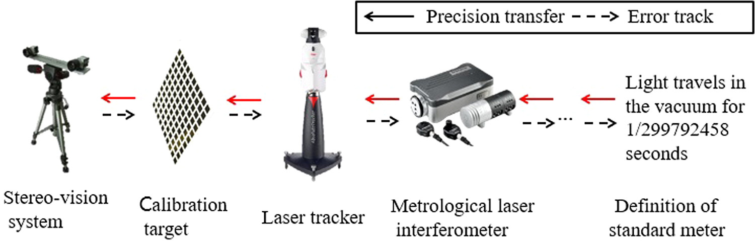
High-accuracy vision system error tracing chain.
First, a feature target used for building virtual 3-D target is designed as shown in Figure 2. a, b, c, d, e, f, g… are M of spherically mounted retroreflectors (SMRs) of laser tracker; I, II, III, IV, V…are N of visual feature points of vision measuring system. The shape of feature target is not necessarily a plane and can be designed according to practical conditions.

Feature target.
As shown in Figure 3, building process of the virtual 3-D calibration target based on designed feature target with a laser tracker is as follows. The coordinate system of the built virtual 3-D calibration target is the same as the laser tracker. Feature target is placed on initial position 0 and the laser tracker can first measure 3-D coordinates Feature target is placed on position 1, which must be within the measurement range of both vision system and laser tracker at the same time. First measure the coordinates In order to ensure accuracy of rigid body transformation, whenever feature target is moved to a new position i, the transform error In the same way, move the feature target position i(i = 1∼K) in measurement space, then measure

Arrangement of virtual targets.
The solving method of high-precision rigid body transform is crucial to construction of virtual 3-D calibration targets. Generally, there are three methods for calculation such as rigid body transform orthogonal decomposition method, singular value decomposition method, and unit quaternion method.
24
Assume that there are two groups of 3-D point sets

In order to obtain unit quaternion, structure N matrix as shown in equation (2)

Where the sums are taken over the elements of


According to two groups of point sets with known corresponding relation, each elements of N matrix can be obtained. The eigenvector corresponding to maximal eigenvalue of N matrix is just the required unit quaternion vector. 24,25 Then, calculate corresponding rotation matrix R with equation (1) and apply Rodrigues transformation for R matrix to obtain rotating vector. Two-norm values of this vector are the rotation angle of rigid body.
In addition, the idea to build large-scale virtual target by high-precision measurement instrument here is a general calibration method for large-scale vision metrology system. 26,27 In practical industrial application, suitable high-precision measurement equipment can be chosen to build virtual target of arbitrary shape in measurement space.
High-precision calibration of visual system
The result of camera calibration is obtained by minimizing the algebra distance, with little physical significance. Therefore, maximum likelihood estimation criterion is used to further optimize all internal and external parameters. 28,29 Its essence is to make the quadratic sum of the distance between theory image point and the actual image point minimum, that is, making the whole reprojection error minimum. The theory image point is calculated with projection transformation. Assume that we shoot n calibration target images and have m reference points on calibration board, then equation (6) is minimized optimized objective function

Where i represents the index of the i-th image, j represents the j-th point on the i-th image,
The calculation process above does not in consideration for the optical distortion of lens. Pinhole imaging model is nothing but an ideal linear model. In fact, camera lens contains radial distortion and tangential distortion meantime. 30 –32
In order to improve the accuracy of the camera calibration and system algorithm efficiency, third-order radial distortion model and second-order tangential distortion model are adopted in this article. Third-order radial distortion model and second-order tangential distortion model are shown in equations (7) and (8). Assume that two axes of image coordinate system are completely vertical, then final nonlinear distortion model is shown equation (9)
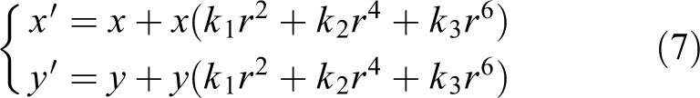


Thereinto,
Assume that we shoot M feature target images and there are N feature points on every feature target, then we only need to acquire 2 M × N equations, that is, we can solve initial values of calibration parameters with least square method and put initial values of these parameters in equation (6) and conduct iterative optimization with Levenberg–Marquardt algorithm, until convergence of iterative process. Then, we may obtain precise inner and outer parameters of camera and lens distortion parameters. 33,34
Experimental study
In this article, a binocular stereo vision system was constructed for verifying the validity and precision of the proposed calibration method. The experimental setup is shown in Figure 4 which consists of the stereo vision system, a graphic workstation, a Leica LTD 840 laser tracker, whose accuracy is 15 µm ± 6 µm/m, and a set of visual feature points (at least three targets). The LTD 840 laser tracker is made by a leading switzerland measuring system manufacturer, Leica. Among them, the stereo vision system is composed of two monochrome CCD industrial cameras with a resolution of 2448 × 2050, Kowa 10 megapixels lens with low distortion, and 940 nm infrared filters. The Kowa10 megapixels lens is made by a leading Japan camera manufacturer, Kowa. For the purpose of improving the overall stability of the measurement system, a vision system was mounted on a heavy-duty tripod. The absolute positioning accuracy of the laser tracker is 0.013 mm within 3 m measuring range and that of the T-probe is 0.025 mm within 3 m measuring range.

Experimental setup.
In order to ensure the validity of the test accuracy, the experiment was conducted under very strict environment. By fully evaluating various possible error sources, improving methods, and controlling the environment, the influences of most errors on experimental measurement were reduced, and the quality of measurement is therefore improved. Considering that the temperature, air pressure, and humidity will affect the atmospheric refractive index and the accuracy of distance measurement will be changed. Therefore, in order to eliminate the influence factors of meteorological conditions, meteorological sensors equipped with laser tracker were used to ensure good stability. In addition, temperature has a special impact on the measurement accuracy of laser tracker. Temperature changes will not only affect the state of the laser tracker but also will cause changes in the size of the measured object. More importantly, these changes are difficult to correct. Therefore, 20° is required to ensure the accuracy of the test. In addition, the movement of the instrument and the slight vibration of the measured object will affect the test accuracy. Fixed devices are used to ensure that the measurement system does not vibrate. Besides, in order to avoid the position between the instrument and the benchmark changed, this experiment will regularly remeasure the benchmark. In order to reduce the influence of processing error caused by reflection, the attitude of the reflector is required to remain the same as that of the instrument, making sure there is a good contact between the reflector ball and the target base. Besides, no dust and debris will affect the test accuracy.
Figure 5 shows the layout of the feature target, which mainly includes five laser tracker target holders and four active infrared LED, where the LED are constructed with cylindrical boss, as shown in Figure 6. This construction is not only convenient for visual observation, but also with the help of it, the laser tracker can obtain three points on the cylindrical surface with the T-probe and fit a space cylinder and obtain the 3-D coordinates of the center of the circular board with the collected three points on it. As the center is identical to the center of the spot observed by the visual system, the virtual target can be constructed. In the experiment, for every new position that the target is placed, its rigid body transformation error will be verified to ensure the accuracy of the virtual target.

Arrangement of feature target.

Structure of infrared LED feature.
The positioning of the calibration target should cover the entire measurement space in various positions and postures as much as possible. In the calibration experiment, feature targets were placed approximately every 0.5 m along the horizontal, vertical, and depth directions to construct large-scale virtual stereoscopic targets. Finally, 212 high-precision 3-D feature points were obtained in the measurement space. The virtual stereo target constructed is shown in Figure 7.

Arrangement of virtual targets (unit: mm).
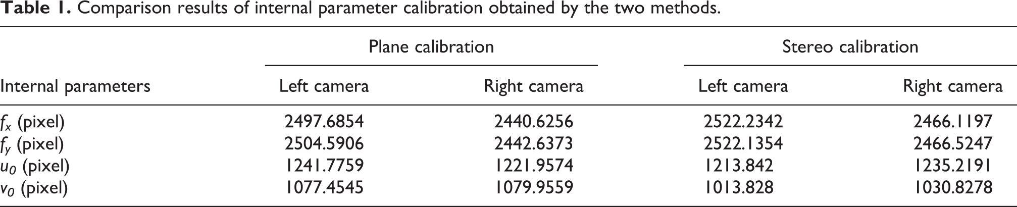
In order to compare the difference between the stereo calibration method and the traditional plane calibration method, a checkerboard calibration plate was also used for calibration in the identical environment. The calibration board corners were arranged in the format of 10 × 10 squares. The side of each mesh is fix at 60 ×60 mm2. The camera distortion calibration was calculated with equation (9), and the calibration results of the two methods are shown in Tables 1 to 3.
Comparison results of internal parameter calibration obtained by the two methods.
Comparison results of camera distortion calibration obtained by the two methods.

Comparison results of outer parameter calibration obtained by the two methods.

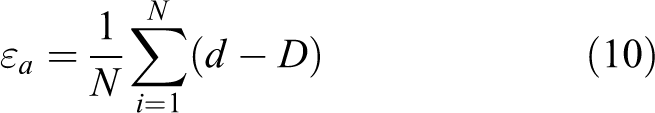
Afterward, the dot pitch measurement experiment was conducted. For the purpose of verifying precision of the system, the tracker target holder was fixed on the high-stability movable platform of the linear slider. The linear slider was calibrated using a laser tracker. The measurement results showed that the standard deviation of the measurement error is 0.018 mm and the longest distance of linear slider is 940 mm. As shown in Figure 8, the camera can track the infrared LED target on the target holder. In the experiment, the actual moving distance D of the moving target holder can be obtained by tracking the target ball with the laser tracker, which is taken as the theoretical value. The position of the feature target before and after moving was, respectively, reconstructed in the measurement coordinate system by the stereo vision system, by means of tracking the position of the infrared LED target point on the moving target in the image coordinate system. Therefore, the target movement distance d can be obtained. The mean value of the measurement error

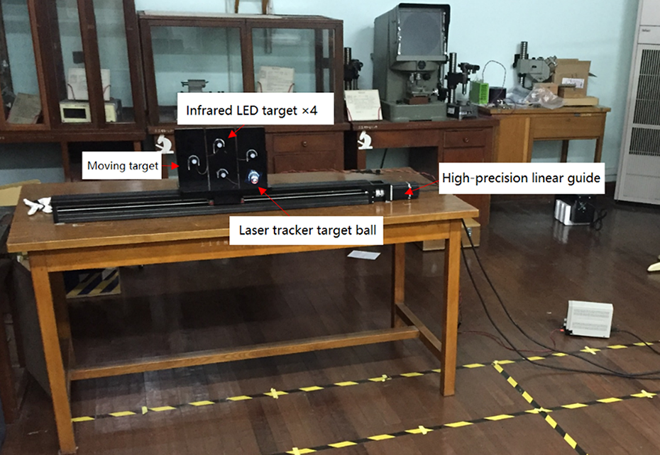
Accuracy verification experiment.
For the purpose of verifying measurement precision of the stereo calibration method and the traditional plane calibration method, 3-D reconstruction was performed at a measurement distance of approximately 3 m based on the calibration results of the two methods. The measurement objects were arranged, respectively, at the transverse dot pitch of 10, 20, 50, and 100 mm, each length was measured 10 times. The experimental results of absolute errors and uncertainty measures are shown in Figure 9 and presented in Table 4. The uncertainty can be obtained by equation (12). The mean error of the plane calibration method is 0.301 mm, and the standard deviation is 0.250 mm; the mean error of the stereo calibration method is 0.002 mm, and the standard deviation is 0.071 mm. It can be seen from the measurement results that the accuracy of the traditional planar calibration measurement is much lower, and the measurement error would increase when the measured dot pitch increases. Comparing with traditional plane calibration method, the measuring accuracy of the stereo calibration method has been greatly enhanced.


Comparison with the measurement system absolute error by different calibration methods.
Uncertainty measured by different calibration method.

For the purpose of verifying accuracy of the proposed method in entire measurement space, several sets of transverse dot pitch (the maximum length is 900 mm) of different lengths were measured using stereo calibration data at the distance of approximately 2, 2.5, 3, 3.5, and 4 m, respectively, and the distance between the dots pitch was arranged to cover horizontal space of about 4 m to the maximum. The experimental data are shown in Table. 5.
Vision system accuracy by stereo calibration method.

The results show that the large FOV high-precision vision calibration method based on virtual 3-D target own higher accuracy and smaller error fluctuation that is fit for the calibration of large-scale vision metrology system.
Conclusion
In this article, the accuracy of FOV vision system and the disadvantages of traditional calibration method in FOV measurement condition were analyzed. In addition, a continuous error tracing chain of high-precision visual system was listed, a method based on the laser tracker was designed, and a virtual stereo target was constructed and a large field high-precision camera was calibrated, based on the idea of error tracing. The universal method can be used to control accuracy and design shape of virtual stereo target according to industrial environment. In terms of calibrating algorithm, the high-order distortion camera model as well as calculation efficiency was taken into consideration. Besides, the calibration parameters were solved with Levenberg–Marquardt (LM) iterative algorithm. In the experiment, the binocular stereo vision system was designed with FOV of 4 × 3 × 2 m3. The feasibility and precision of the proposed method were verified by measuring transversely dot pitch on the high-precision guide. First, checkerboard calibration board method and stereo calibration method were used to calibrate in the identical environment. Then, dot pitches were measured, respectively, and the measurement precision of two calibration methods was compared. The proposed method was used to obtain the accuracy in the whole measuring range in the space. Thereinto, 152 groups of transversely dot ditch of different lengths were obtained at measurement distance of approximately 3 m. The mean value of error was calculated −0.003 mm, and the standard deviation of the error was calculated 0.080 mm. Experiment result shows that large FOV high-precision vision calibration method based on virtual stereo target proposed in this article can effectively improve measurement precision and reduce measurement error fluctuation. Therefore, it has practical application value.
Footnotes
Acknowledgment
The authors appreciate the financial support from Nation Key Research and Development Plan and the Nation Natural Science Foundation of China.
Declaration of conflicting interests
The author(s) declared no potential conflicts of interest with respect to the research, authorship, and/or publication of this article.
Funding
The author(s) disclosed receipt of the following financial support for the research, authorship, and/or publication of this article: This work was supported by Nation Key Research and Development Plan (2016YFC0302402) and the Nation Natural Science Foundation of China (51205243).