
Abstract
This article aims to present the influence of the measurement uncertainty of a commercial laser tracker on the volumetric verification of a machine tool through the study of verification procedures that are affected by measurement uncertainty, multilateration and laser tracker self-calibration. Self-calibration provides relative positioning between measuring coordinate systems (laser trackers) and the reference system from the measured points of the same mesh. The measured points are affected by the noise of each laser tracker; therefore, they provide positions that are different from the real positions of the laser trackers. By applying the technique of multilateration and by knowing the positions of the laser trackers, the measurement noise can be reduced. The range of the measurement noise reduction is influenced by the radial measurement noise of the laser tracker, the distance between the laser tracker and the measured point and the techniques that multilateration and laser tracker self-calibration employs. This article presents different laser tracker self-calibration procedures, a least squares adjustment, trilateration and quadrilateration as well as the scope and appropriateness of each method relative to the laser tracker measurement noise. Moreover, the influences of radial laser tracker noise on the trilateration and quadrilateration techniques are described as well as the influence of the distance between the laser tracker and the measured point on multilateration.
Keywords
Introduction
Today, modern manufacturing technology demands efficiency and accuracy in machining. The gradual implantation of open architecture control software installed in a new generation of machine tools (MTs) compensates for the MT geometrical errors that are obtained in the volumetric verification, thereby improving the accuracy of the machine.
Traditionally, MT accuracy has been ensured by verifying each of the axes that compose the MT in a process known as geometric verification.1–3 Currently, due to the strong push of sectors, such as the eolic, rail or naval sectors, which demand the machining of large parts with high accuracy in long-range MTs, volumetric verification with laser trackers (LTs) is being implemented progressively as a new verification technique.4–9 Volumetric verification determines the behaviour of the machine in its entire workspace in less time than geometric verification, 2 providing an overall correction of the combined effect of all the geometric errors of the MT, thereby minimising its volumetric error (ve). When the geometric errors are characterised, their influences are compensated for using MT software control. The correction provides global compensation of the geometric errors. Consequently, the approximation function of each geometric error is not required to coincide with its physical meaning. The accuracy of the geometric error approximation functions obtained in the volumetric verification depends on the measurement system characteristics (LT), the techniques used and the number of LT employees. Additionally, self-calibration of the LTs is a measurement requirement.
An LT is a portable measurement system that provides the position of a point in spherical coordinates. This position is determined by comparing a measurement beam and a reference beam from the combination of a laser interferometer and the readings of the azimuth as well as the polar coordinates of the angular encoders, which provide two rotational degrees of freedom of the LT. Of all the sources of error10,11 that affect the LT, the measurement noise resulting from the uncertainty of the interferometer and the uncertainty of the angular encoders provides the greatest contribution to the measurement uncertainty.
The influence of the measurement uncertainty on the measured points is reduced by applying a multilateration technique.12–16 The measurement error reduction obtained by multilateration is determined by the number of LT employees, the spatial distribution of these employees relative to the MT workspace and the relative position between the LTs that have been obtained by applying LT self-calibration to the entire measurement system that is formed by the individual LT measurement systems.
The relationship between the global reference system and the MT and LT coordinate system is presented in the kinematic model of the machine. The accuracy of this relationship is directly related to the self-calibration technique used and the measurement noise of the LTs. The lack of precision in this process results in the correction of an error, which does not exist in the MT. The self-calibration error will affect the approximation functions of the MT geometric errors obtained in the volumetric verification.
This article aims to demonstrate the influence of radial and angular measurement uncertainty on the results of the volumetric verification of an MT using an LT and multilateration. Therefore, a study on the influence of radial and angular uncertainty on volumetric verification using multilateration is presented. Similarly, the self-calibration techniques of quadrilateration, trilateration and least squares adjustment from which we obtained the relative LT positioning are presented too.
The external influences on volumetric verification by a LT
Volumetric verification consists of minimising the ve of the MT. The ve is defined as the difference between the pairs of nominal points introduced by a numerical control (NC) and the actual points achieved by the MT. This measurement provides an overview of the machine error from the mean ve
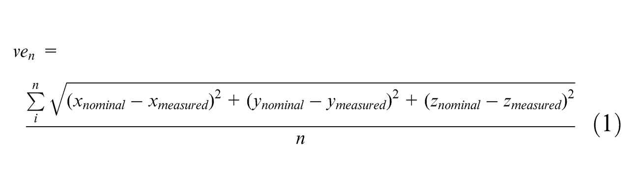
Theoretically, the ve of an MT is solely the consequence of the positioning error of the MT in its workspace. This error is the result of the MT geometric errors. Minimisation of the difference between the real points captured by the LT and the NC nominal points will reduce the ve of the MT to improve its accuracy. The NC points and LT measured points are related with MT kinematic model.
The kinematic model of the machine depends on the structural configuration, the number of axles and the sequence of motion of the MT.6,7 The mathematical model of the machine, in which the position of the tool relative to the LT is determined as a function of the movements of the MT, is obtained depending on the MT’s configuration. The positioning of the LT in the MT kinematic model depends on the structure of the machine. The LT takes the position corresponding to the part, and the reflector takes the position corresponding to the tool.6,7 The LT must be situated on the bench or in a mobile structure according to the machine to be verified (Figure 1).
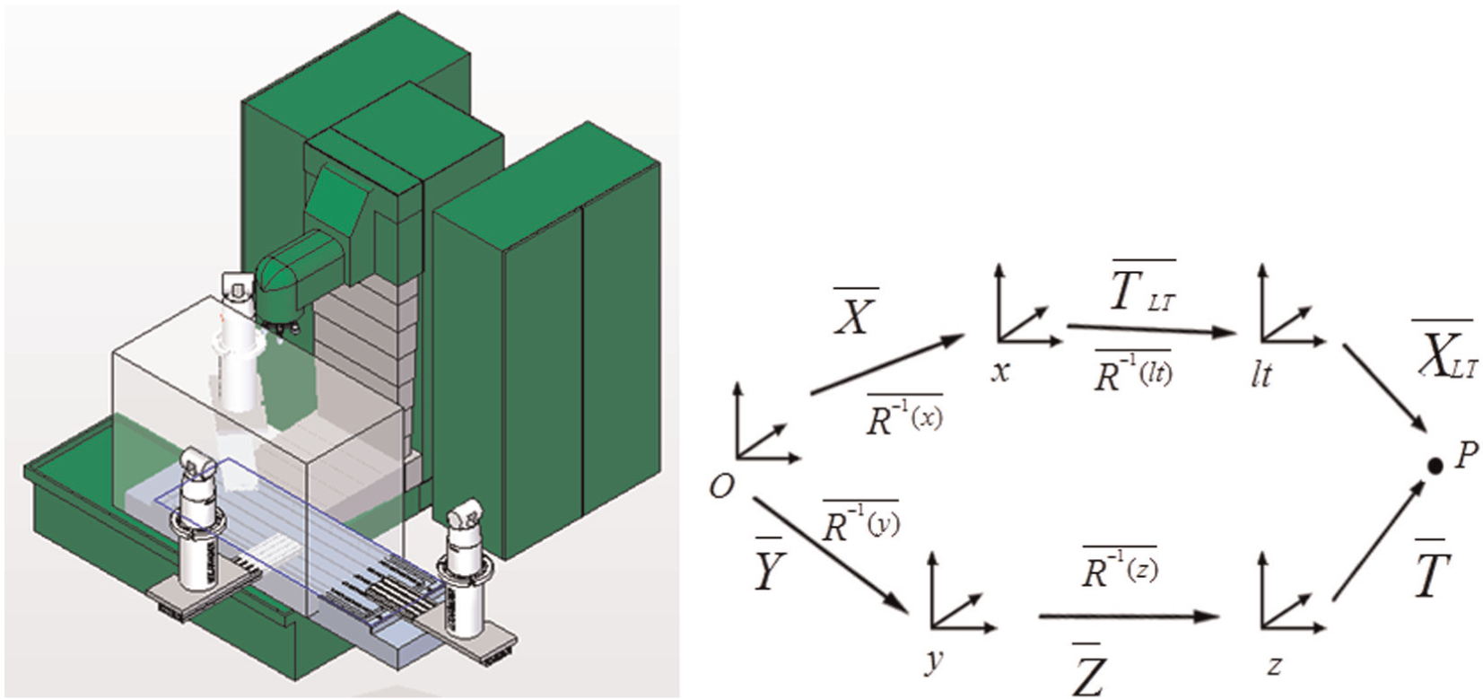
Kinematic model of the machine tool used in tests.
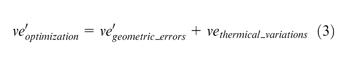
The kinematic model of the MT is not affected by the presence of external factors. However, the structural components that define the kinematic chain, which are obtained by the equation of motion, are dimensionally modified. As a consequence of structural deformations, load distributions or temperature gradients are present. When the difference between the theoretical and real points is calculated, the dimensional variations modify the value of the real points that are captured by the LT. Most of the variations are due to temperature deformations. Therefore, this model can be considered to be an independent error model. These variations ensure that the ve will consist of the sum of the effects of the geometric errors of the MT plus a term resulting from the structural dimensional variations of the kinematic chain
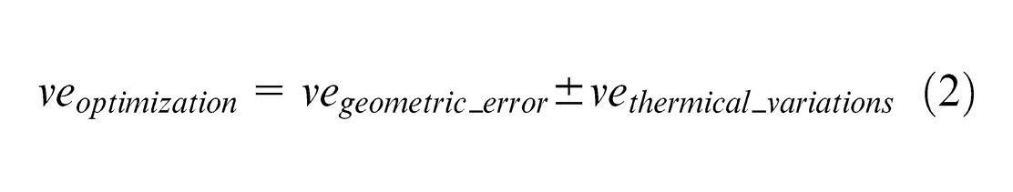
The approximation functions obtained from the ve (equation (2)) not only minimise the combined effect of the geometric errors but also attempt to compensate for the effects of the temperature variations in the data. For this reason, it is necessary to capture the points in a controlled environment by eliminating possible sources of thermal gradients, such as light sources and drafts.
Similarly, the measurement uncertainty resulting from the characteristics of the LT employed also affects the actual coordinates of the measured points, especially the measurement noise (Figure 2).
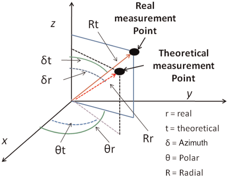
Influence of measurement noise.
The functions of the geometric error obtained during verification attempt to compensate for the influence of the measurement noise on the measured points. If a point is measured from at least three different positions and the multilateration technique is applied, the influence of the measurement noise on the characterisation and subsequent compensation of the geometrical error can be reduced, thereby improving the precision of the MT

There are two meshes of points, one in the machine coordinate system, which corresponds to the nominal points, and the other in the LT coordinate system, which is affected by the dimensional variations of the MT and the measurement uncertainty of the LT. With the aim of obtaining the relationship between the different coordinate systems, it is necessary to perform the process of self-calibration for the LTs employed with respect to the machine coordinate system (Figure 3). The accuracy of this process depends on the accuracy of the captured points.
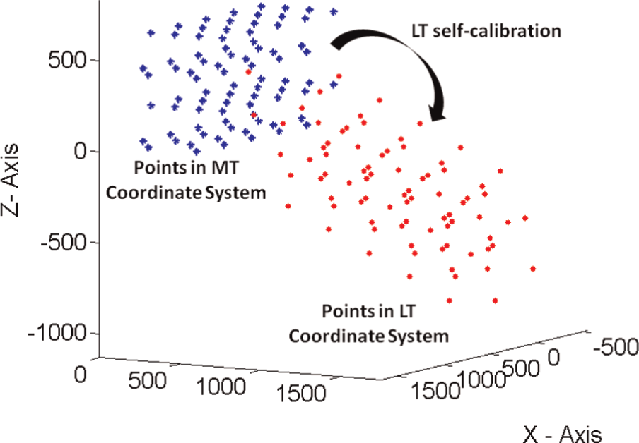
Obtaining transformation matrix.
Multilateration in MT volumetric verification using commercial LTs
The technique of multilateration calculates the coordinates of a measured point from the measurement information of that point from three or four different positions using only the radial component measured by each LT.7,10,12–21
When a point in the MT workspace in the machine reference system (CSMT) is measured using three LTs (i = 1, 2, 3), the point can be measured in three different coordinate systems (CSLTi (i = 1, 2, 3)). If the measured point is transformed from CSLTi (i = 1, 2, 3) to SCRef, there will be three close but different points as a result of measurement noise (Figure 4).
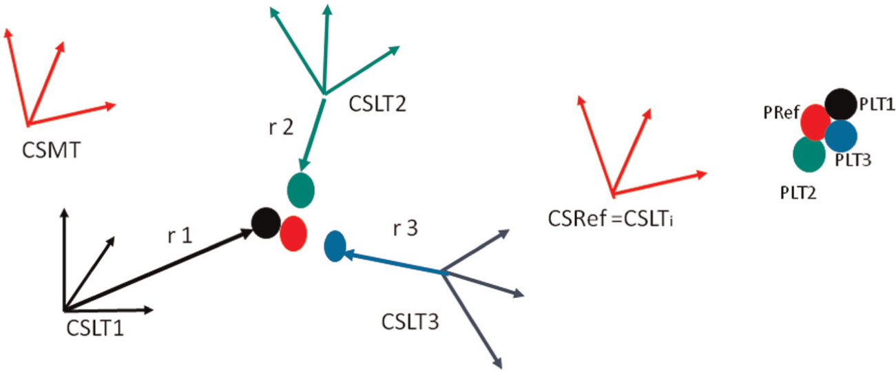
Measurement of the same point with three different LTs.
Different techniques for solving the system of equations proposed by multilateration (equation (5)) have been introduced and studied in several articles. They can be mainly divided into analytical and geometrical resolution techniques 15
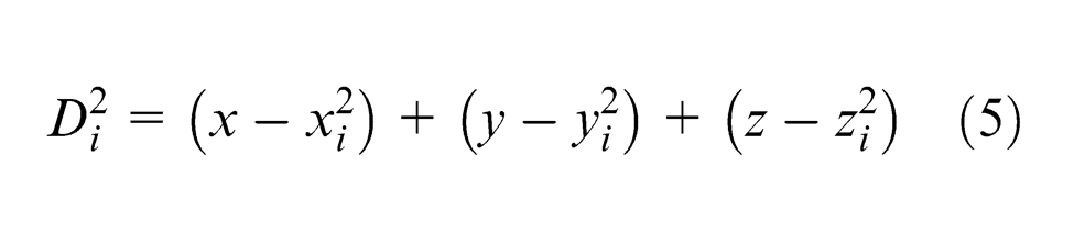
Analytical resolution is based on simplifying the system of equations that provides the positioning of the LTs in a reference system. To accomplish this task, it is necessary to generate an auxiliary reference system in which the origin of the new system NCS is the same as that of CSLTi. The x-axis is created when the origins of SCLTi and SCLTj≠i are connected. The y-axis is defined so that the origin of SCLTk≠j≠i is included in the xy plane. 7 The resolution of the new simplified system of equations, if three LTs are used, is defined by equations (6)–(8)
The resolution of the system of equations with the addition of a fourth LT is given by equation (9) as follows
The measurement noise reduction range is determined by the relative positioning of the LTs about a set of points to be measured, the spatial angle between the LTs15,16 and the measurement uncertainty of each measured system used (Figure 5).
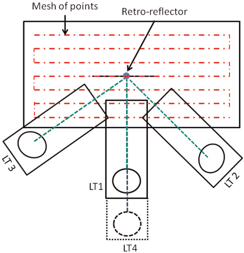
Spatial distribution of the LTs.
Motives, techniques and parameters of control in LT self-calibration for MT volumetric verification
In the last few years, there have been several studies on the scope of the multilateration technique regarding the changes in the spatial distribution of the LTs and their positions with respect to the points to be measured. However, no detailed study has been completed that investigates the influence of the measurement uncertainty of the LTs employed on the MT volumetric verification.
The basic principle of verification consists of minimising the difference between the pairs of theoretical points that are within the MT coordinate system and the real points captured by the LT in the LT coordinate system. The minimisation is based on the identification of the MT geometric errors using non-linear optimisation based on actual and theoretical points.
To compare the pairs of points, these points must be in the same coordinate system. Therefore, it is necessary to determine the position of the LT in the reference coordinate system. The scope of multilateration in noise measurement reduction and the fitness of approximation functions obtained through volumetric verification greatly depend on how accurately the relationship between the different coordinate systems, CSLTi and CSMT, was obtained.
Parameters of control
To compare the different methods of self-calibration, two parameter controls are defined as follows.
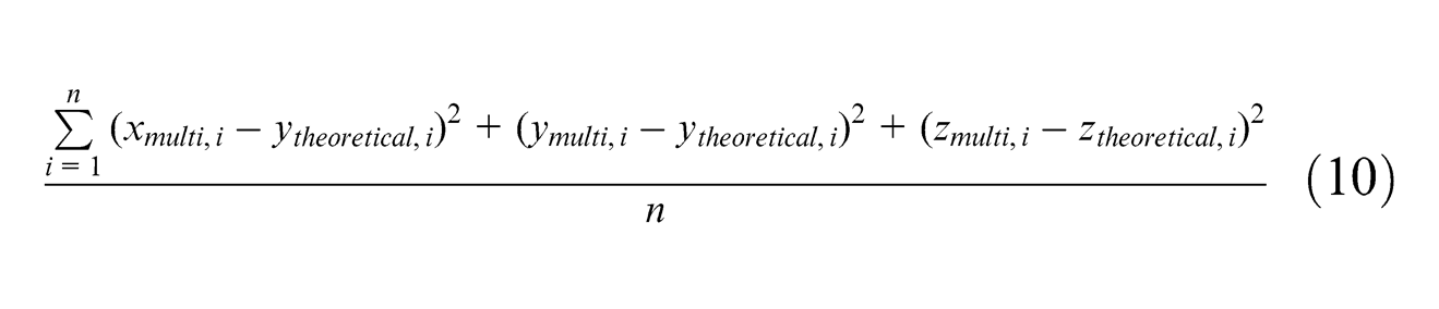
First parameter
This is the difference between the multilateralised coordinates and the theoretical points without measurement noise in the same reference system CSMT = CSN
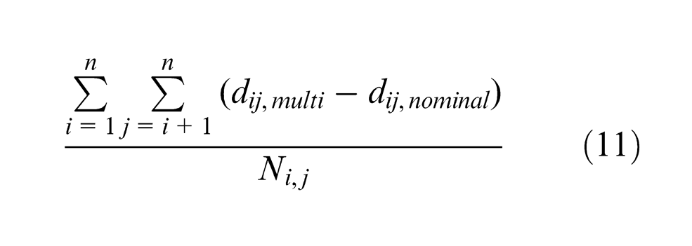
Second parameter
This is the comparison of the distance between the points in the different coordinate systems by calculating the distances to all the points between them. If the number of points is n, the distances calculated are between 1 and i, with i = 2, …, n; between 2 and i, with i = 3, …, n and so on. Comparisons are performed between the distances calculated between the nominal points without measurement noise and in CSMT and the distances calculated between the multilateralised points in CSRef. With Ni,j, the number of distances is calculated
Techniques of LT self-calibration
The LT self-calibration techniques presented in this section are related to a correction of the effect of angular measured noise of each LT in data capture. These techniques do not provide a correction of the LT errors unlike other self-calibration techniques.
Self-calibration by least squares
This self-calibration technique obtains the roto-translation matrix between coordinate systems regardless of the number of LTs used, thereby minimising the difference between coordinates SCRef and SCLTi 15
The relative positioning of the LTs using this method requires the selection of a mesh as a reference system. By selecting CSRef as the reference system and the mesh of the points measured by LT1 and using a least squares fit between LT1_mesh and LT2_mesh, the relationship between LT2 and LT1 can be obtained. Similarly, the relationship between LT3 and LT1 can be obtained. The reference points (Pts LT1) and the set of points (Pts LT2, Pts LT3) are affected by measurement noise. Therefore, the obtained positions of CSLT2′ and CSLT3′ are not the real positions of the LTs CSLT2 and CSLT3 (Figure 6).
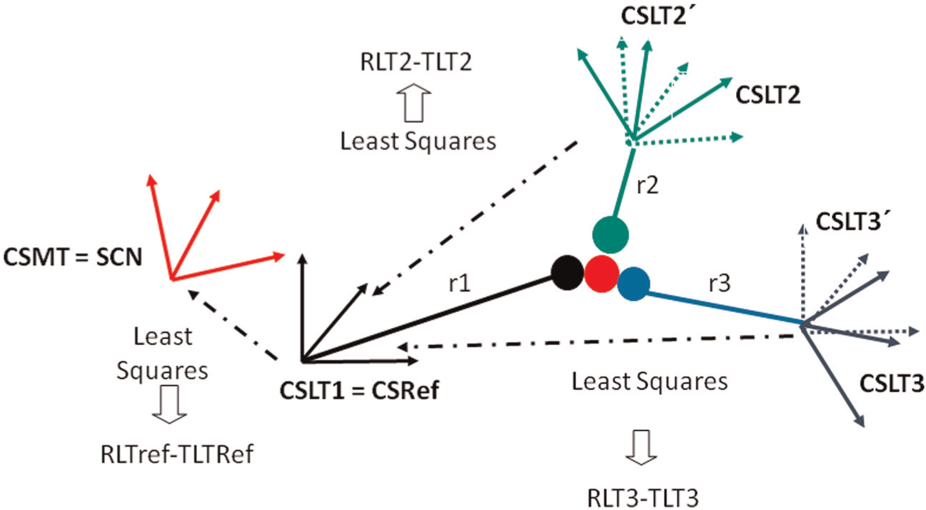
Least squares laser tracker self-calibration.
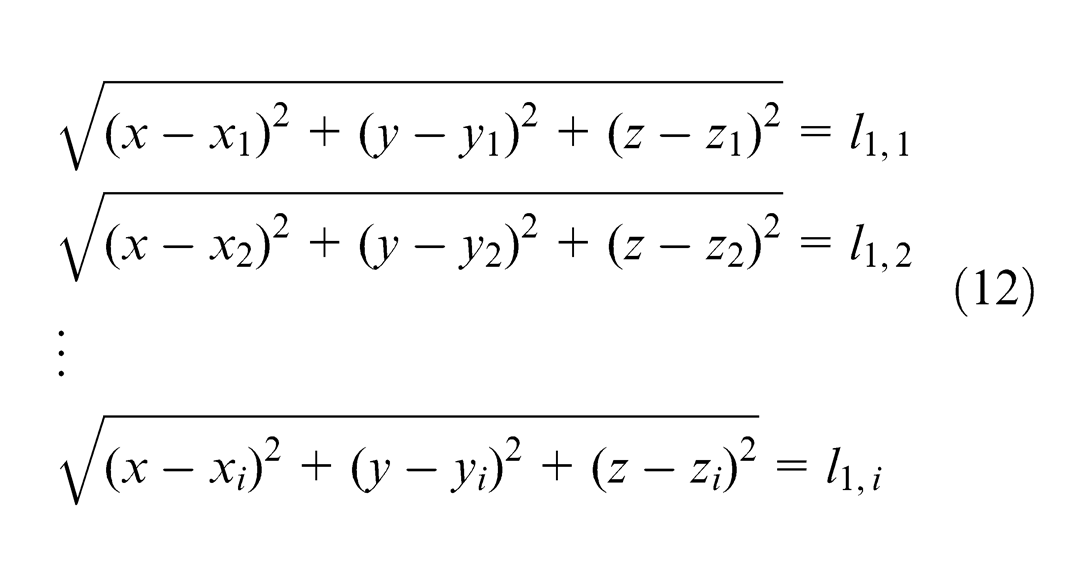
The positions of the LTs (xi yi zi) with respect to the reference system CSRef and the radial component of the measured points by the three LTs, multilateralised points, r1,i, r2,i and r3,i, are obtained using the intersection of the spheres.
The accuracy of the self-calibration using the least squares method with intersection of spheres depends on the difference between the nominal and multilateralised coordinates. For both sets of points to meet in different coordinate systems, that is, CSLT1 = CSRef and CSN, a direct comparison of the coordinates cannot be performed. Therefore, the differences in the distances from one point to all the other points in both sets of points are compared using the second parameter of control. To compare the nominal and multilateralised coordinates, it is necessary that both coordinates be in the same coordinate system. As a result of the measurement noise present in the LT1 mesh, which is used as a reference, there is a difference between SCN and SCRef. It is necessary to perform an adjustment between the nominal mesh and the multilateralised mesh to determine the relationship between SCRef and SCN. When the multilateralised coordinates are transformed to SCN, the nominal coordinates and the multilateralised coordinates can be compared and the first parameter of control can be calculated (Figure 6).
Self-calibration by quadrilateration and trilateration
Self-calibration using trilateration and quadrilateration not only allows us to obtain the positions of the LTs for the measured points but also optimises the points from the data captured by each of the LTs.15,16 Therefore, the relative positions and the multilateralised points are obtained simultaneously using only the radial component of each point measured with each LT (Figure 7).
Quadrilateration laser tracker self-calibration.
Similar to the method of least squares, it is necessary to know the relative positions of three or four LTs. To accomplish this task, we can use the coordinates obtained from the measurements of the same mesh of points for each LT. For an optimisation process, self-calibration by optimisation depends strongly on the optimisation’s initial values. Therefore, a pretreatment using least square is performed to obtain suitable initial values. The mesh of points measured by LT1 is selected as the reference mesh; therefore, SCLT1 = SCRef. Applying a least squares fit between the LT1_mesh and the LT2_mesh, the relationship between LT2 and LT1 is obtained. Similarly, the relationships of LT3-LT1 and LT4-LT1 are obtained. Once the relationship between LTi and LT1 is known, a new coordinate system CSMulti is created according to the following rules (Figure 8).
The origin of CSMulti is the same as that of CSLT.
The x-axis is determined by binding CSLT1 to CSLT2. Therefore, the relationship between SCLT2 and SCLTMulti is given by P1 (x1 0 0).
LT3 is located in the plane formed by LT1 and LT2, which is defined using P2(x2y2 0).
LT4 can be found at any point P3(x3y3z3).
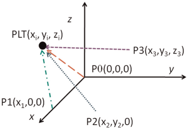
Multilateralised system.
The initial values of the optimisation parameters (x1x2y2x3y3z3) are obtained by changing the relative positions of the LTs, which are obtained using the least squares method and vary throughout the optimisation, to the new coordinate system, SCMulti. Apart from the positioning parameter of the LTs (x1x2y2x3y3z3), it is necessary to obtain suitable initial coordinate values of the mesh-measured points in SCMulti. This task is achieved by changing the coordinate systems of the measured points by LT1 in CSLT1 to CSMulti to have them in the same origin CSLT1, CSRef and CSMulti (Figure 9).
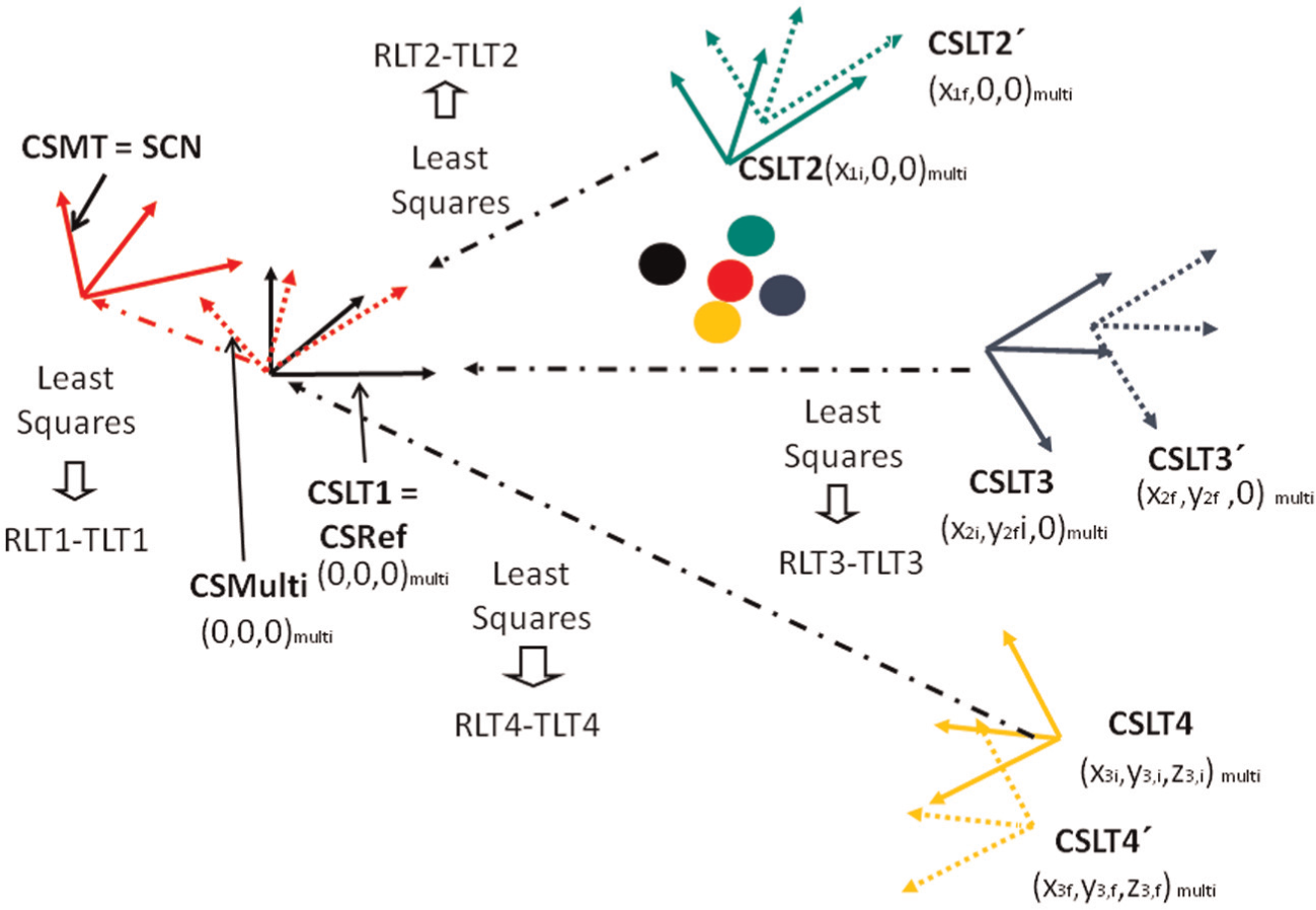
Laser tracker self-calibration using trilateration and quadrilateration.
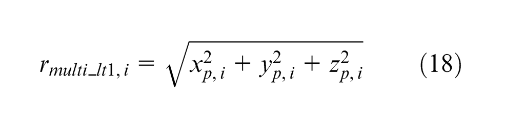
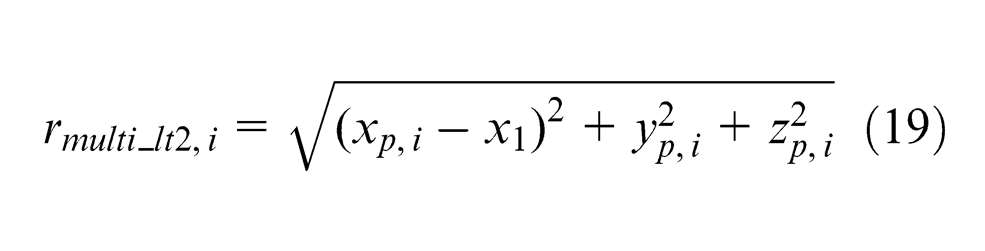
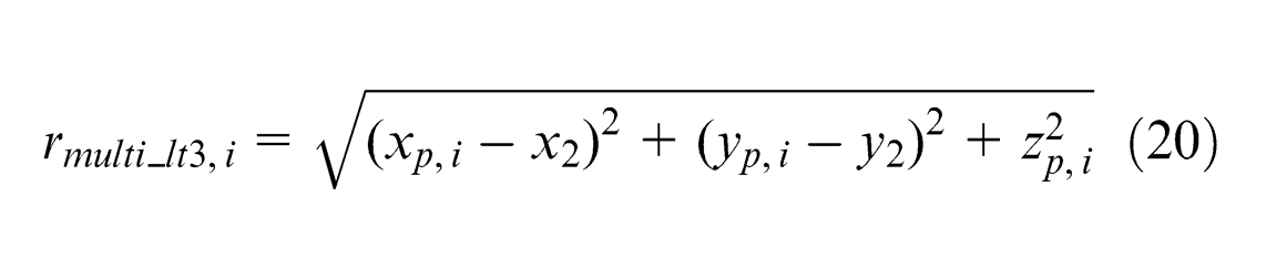
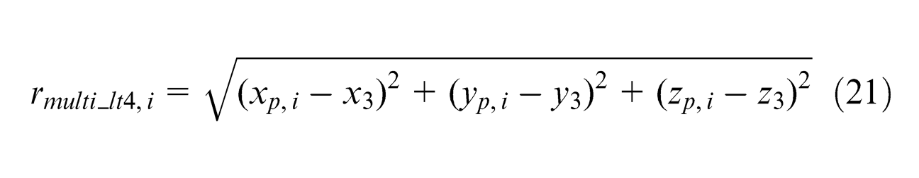
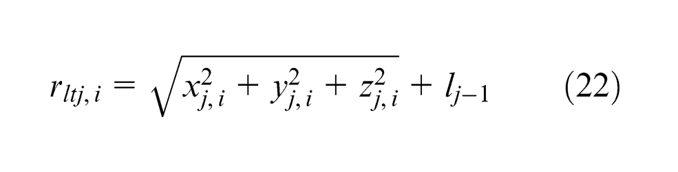
Depending on the type of LT that uses this point, it can be measured in absolute coordinates with Leica or Faro lasers or in relative coordinates, such as with the Etalon tracer. 13 In the case of working with an LT that is measured in relative coordinates, it is necessary to incorporate an li offset to the measured distance for each LT, which is also incorporated into the optimisation vector. Therefore, the optimisation vector is formed by the LT offsets li, the positioning parameters (x1x2y2x3y3z3) and the initial optimisation points xp, i , yp, i and zp, i
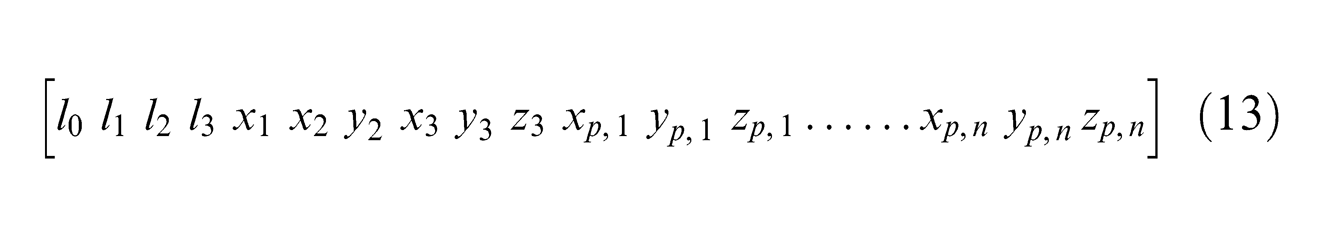
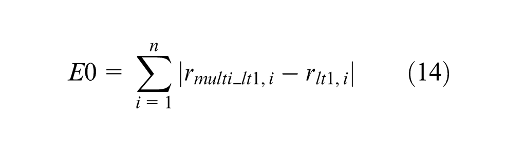
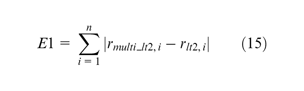
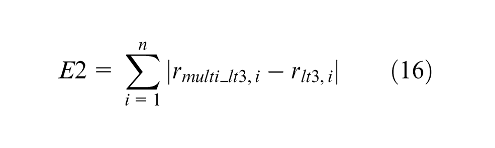
All the parameters of this vector are varied to minimise the error F = [E0 E1 E2 E3], where rltj, i represents the radial component of the point i measured with LT j and rmulti_ltj, i represents the radial component of the point parameter vector xp, i yp, i zp, i in CSMulti (equations (14)–(21))

After obtaining the multilateralised points in CSMulti, the difference in all the points together is calculated to obtain the second parameter of control. To compare the coordinates of the nominal points with the multilateralised points, it is necessary to obtain the relationship between the multilateralised mesh and the nominal mesh in the same coordinate system, SCN, which is obtained by applying a least squares fit. By transforming the multilateralised points to CSN and comparing them with the nominal coordinates, the first parameter of control is obtained (Figure 9).
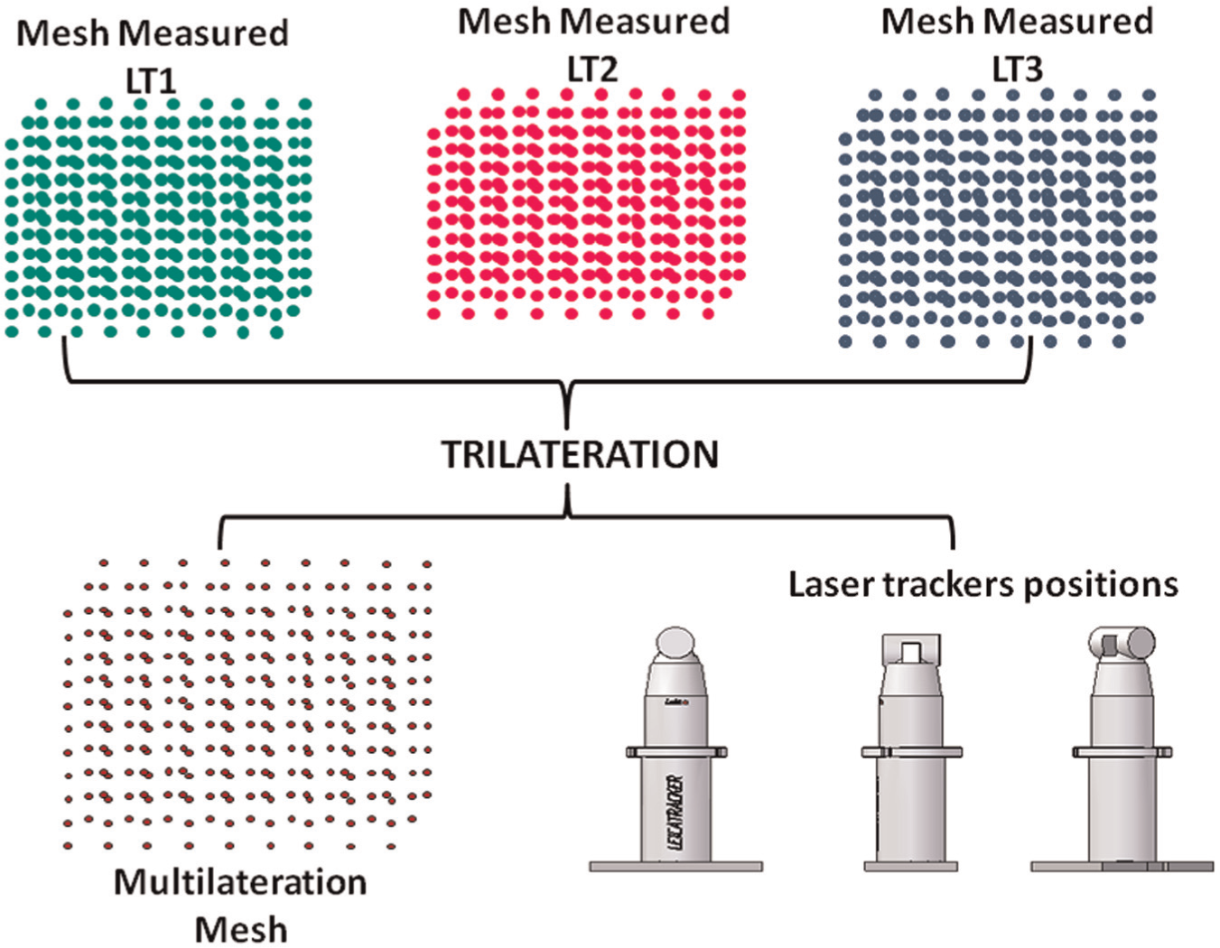
Tests and results
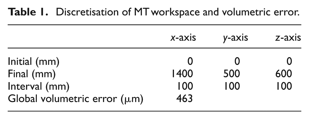
To determine the influence of the characteristics of the LT used on the volumetric verification, a series of synthetic tests was performed. Using a synthetic data generator,6,7 a grid of points was generated according to the data in Table 1. The data were affected by the geometric errors of the machine in Figure 1, which shows a ve of 463 µm. The measurement of the mesh was performed with two different offsets6,7 to avoid coupling of the geometric errors. Therefore, the number of points to measure was 1260, which was sufficient to reduce the influence of the measurement noise.
Discretisation of MT workspace and volumetric error.
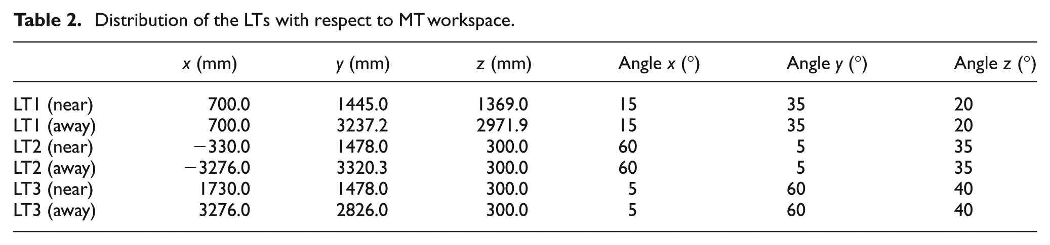
Commercial LT manufacturers provide information on the uncertainty of their measurement systems. Noise can be characterised by measuring an angular uniform distribution of 30 µrad for angular encoders and a uniform distribution of 4 µm/m plus a random term of 0.8 µm for the radial measurement uncertainty. The influence of measurement noise on volumetric verification was studied by simulating the measurement of a mesh of points and varying the radial measurement noise from 0% to 200% of the nominal value. The influence of angular measurement noise was not modified. The radial component depends on the measurement distance. Therefore, the same tests were performed by changing the distance to the measured points while maintaining the spatial angle between the LTs (Table 2).
Distribution of the LTs with respect to MT workspace.
The ve resulting from the geometric errors remained constant in all tests (blue line on the left graph of Figure 10). However, as observed in Figure 10, the initial ve using a single LT depends on the measurement noise that is introduced in the measurement point by the LT (green line on the left graph of Figure 10). In applying the multilateration technique, the initial ve was similar to the ve as a consequence of the MT geometric errors, thereby increasing its initial ve value when the characterisation of the LT radial measurement noise was modified linearly (purple line on the left graph of Figure 10).
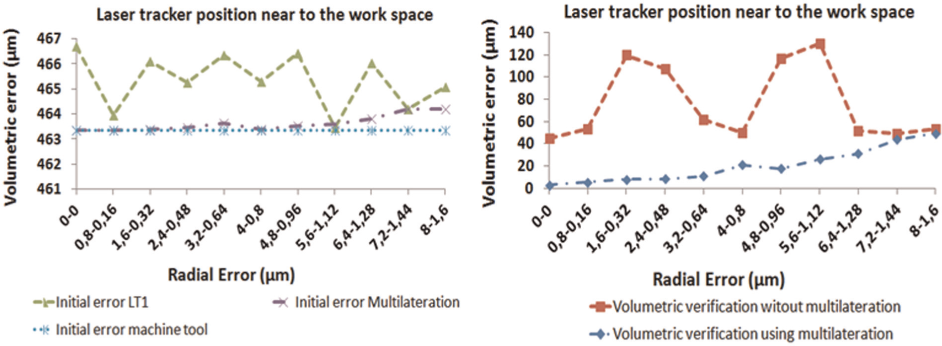
Influence of radial noise on volumetric verification.
The right graph of Figure 10 shows how the residual ve using multilateration points with three LTs and intersection of spheres, knowing the nominal LT positions, is smaller than the residual ve of data captured with one LT. Similarly, blue line on the right graph of Figure 10 shows how an increase in the initial ve as a consequence of radial noise causes a greater increase in the final ve.
If the distance from the LT to the workspace is increased, using the same techniques in data from Figure 10, the influence of the LT measurement noise and the initial ve is also increased (Figure 11).
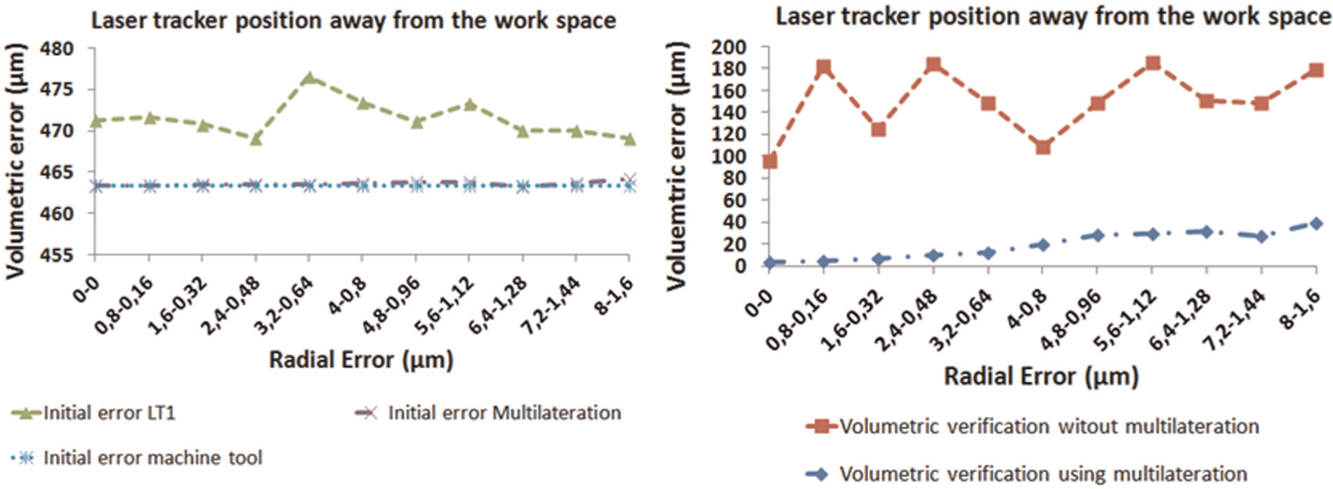
Influence of radial noise on volumetric verification.
If the LTs are removed from the workspace, the final ve using an LT is higher than when an LT is near the workspace, as shown in Figure 11. However, if the final multilateration ves are compared, there is no relevant variation in the final ve (Figure 12). This comparison was performed by maintaining the same spatial angle between the LTs.
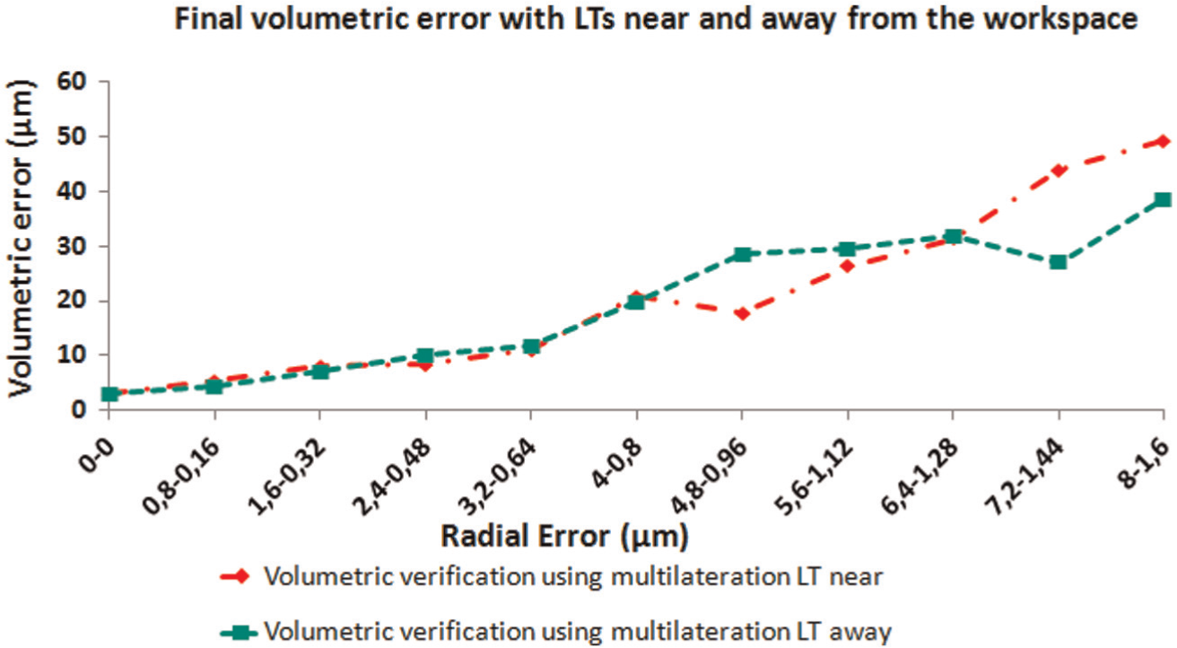
Residual volumetric error changing the LT position.
The positions of the LTs (Table 1) were known in all tests that were performed until this point. Therefore, obtaining these results was conditional on the quality of the LT self-calibration uses.
To determine the difference in each of the self-calibration techniques from the results in which the positions of the LTs were known, a series of tests were performed. The volume of the workspace in which the measurement points were located, as shown in Table 3, yielded a total of 60 points.
Workspace distribution LT self-calibration tests.
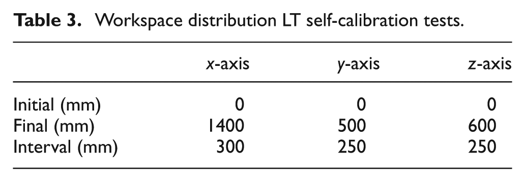
The number of points calculated was lower than the number of points used in the volumetric verification. With the aim of reducing the influence of random measurement noise, 10 measurements of each measurement noise characterisation were performed for each self-calibration technique. The techniques studied were as follows.
LT1 known
In this test, the roto-translation matrix between CSLT1 and CSN is known. When the items have the same coordinate system, the difference between the pairs of point coordinates shows the influence of the noise measurement for each characterisation.
LT1 least squares fit
The roto-translation matrices that relate the coordinates of CSLT1 with those of CSN are obtained using LT self-calibration using the least squares method. The coordinate differences not only show the influence of the noise measurement for each characterisation because the error introduces the influence of the last adjustment using the least squares method. The error introduced by the least squares fit is observed when comparing the results obtained in this test with the results of the test in which LT1 was known.
Multilateration with known position of the LT
In this technique, the roto-translation matrices of each of the LTs used with respect to the CSN are known. The differences between the multilateralised coordinates show the influence of the radial noise measurement on the multilateration.
Multilateration with LT self-calibration using least squares
The roto-translation matrix relating the coordinates of CSLTi with those of CSNominal is obtained through LTi self-calibration using the least squares method. The difference in control parameter 2 obtained with this method compared to that obtained with the nominal positions of the LTs indicates that the error is introduced as a result of the self-calibration. The difference in the coordinates between the points of CSLTi and CSNominal, the parameter of control 1, is affected by the process of self-calibration and the subsequent fit between SCRef and SCNominal. This parameter illustrates the influence of errors on the initial ve of the volumetric verification.
Multilateration with LT self-calibration using trilateration
Using this technique, the relative position of the three LTs employed in capturing the points and the multilateration coordinates of the points are obtained simultaneously (see section ‘Tests and results’). When comparing the parameters of controls 1 and 2, which are obtained in this procedure, with those obtained with the nominal positions of the LTs, it can be observed that the error results from the self-calibration procedure (parameter 2) along with the effect of the adjustment of SCRef-SCN (parameter 1).
Multilateration with LT self-calibration using quadrilateration
Using this technique, the relative positions of the four LTs employed in the capture of the points and the multilateration coordinates of the points are obtained simultaneously (see section ‘Tests and results’). When comparing the parameters of controls 1 and 2, which are obtained in this procedure, with those obtained with the nominal positions of the LTs, it can be observed that the error results from the self-calibration procedure (parameter 2) along with the effect of the adjustment of SCRef-SCN (parameter 1).
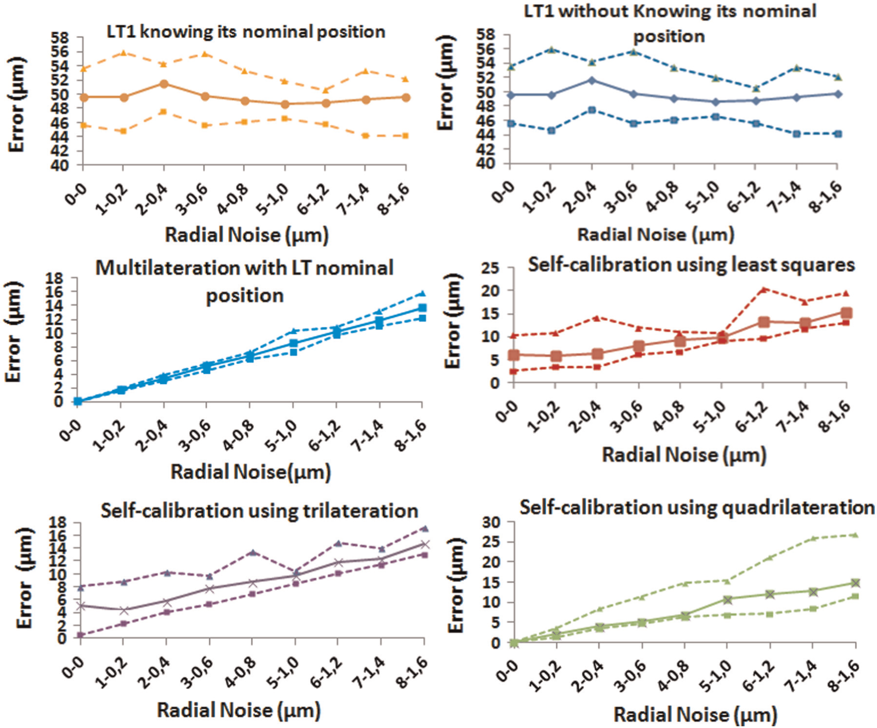
The comparison of the first parameter of control provides the best self-calibration method from which the points obtained have less variation with respect to the points located where the MT is positioned. The randomness of the measurement noise is reduced by repeating each test for each of the measurement noise characterisations. The average error of the 10 tests can be used as a proxy for each value of radial noise in each self-calibration technique. The suitability of this choice is determined by the deviation of the mean error of the 10 tests with respect to the lower test and the test with the highest error for each error characterisation (Figure 13).
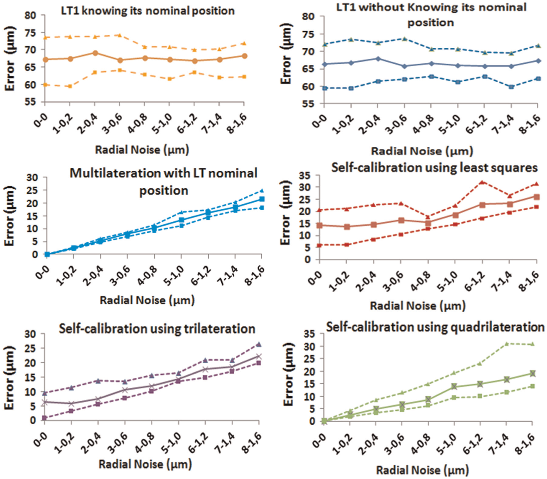
Maximum, minimum and mean values calculated in self-calibration tests modifying radial noise characterisation in LTs. First parameter of control.
In Figure 13, the extent of multilateration in the angular noise elimination can be observed. By increasing the noise in the LT radial direction, the resulting error of the measurement system is increased. This noise has an important effect when multilateration is applied but is negligible compared to the influence of angular noise. In Figure 14, it can be observed that the adjustment of the mesh using the least squares method reduces the measurement noise, which results in the incorporation of the influence of noise on the roto-translation matrix.
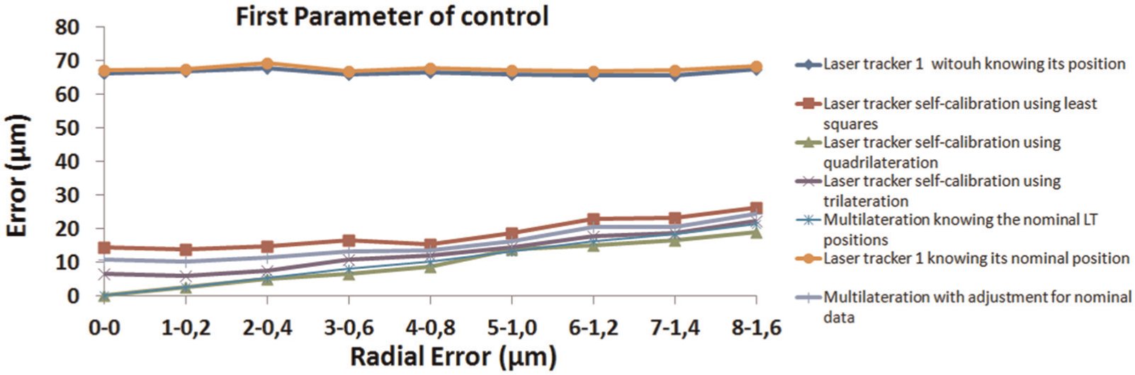
First parameter of control in self-calibration tests.
The self-calibrating process that provides the best coordinates of the points with which to perform volumetric verification is quadrilateration, as shown in Figure 15. The error achieved by quadrilateration self-calibration is less than that obtained with the nominal positions of the LTs. This improvement is a mathematical improvement, not a real improvement, as a result of obtaining the roto-translational matrix between CSMulti and CSMT using the least squares technique.
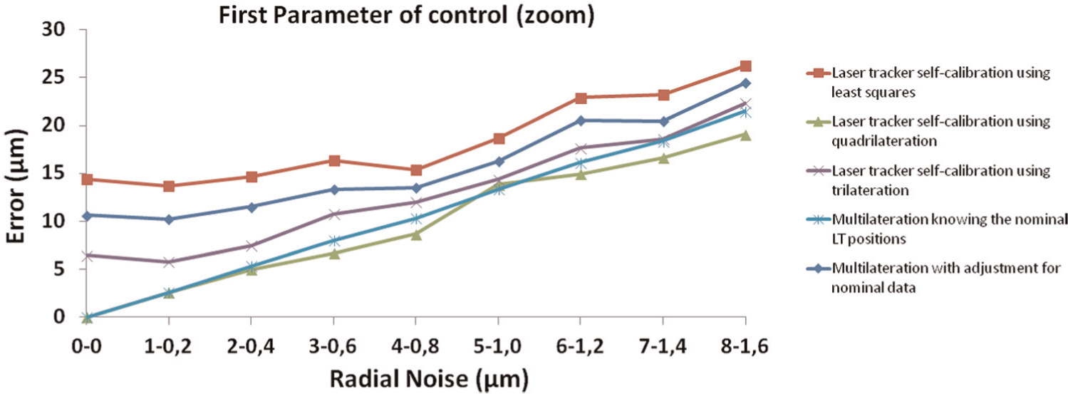
First parameter of control in self-calibration tests (zoom).
The results of the first control parameter indicate what the most suitable technique is for obtaining the measurement points used in volumetric verification. This parameter is affected by a final least squares adjustment that can be used to obtain the relationship between SCMulti and CSMT, which affects the results. The best self-calibration technique is that in which its points in CSMulti have the least variation from the points of CSMT in CSMulti without the influence of measurement noise on the fit between the systems. The points are not compared directly because they are in different coordinate systems. Therefore, we compared the distance between points of the same mesh in their respective coordinate systems. In the same way, the error that was introduced by the least squares fit between both systems was avoided using this parameter of control. To reduce the influence of randomness, we compared the average error of the second parameter of control for tests that were performed using different techniques (Figure 16).
Maximum, minimum and mean values calculated in self-calibration tests modifying radial noise characterisation in LTs. Second parameter of control.
Figure 17 shows the results of using multilateration as a technique to eliminate the influence of LT angular measurement noise. The increasing radial measurement noise is an important influence when the multilateration technique is used and is negligible in comparison with the influence of angular noise. Moreover, in Figure 17, it can also be observed that the adjustment of the mesh by least squares reduced the noise measurement, introducing its influence on the roto-translation matrix.
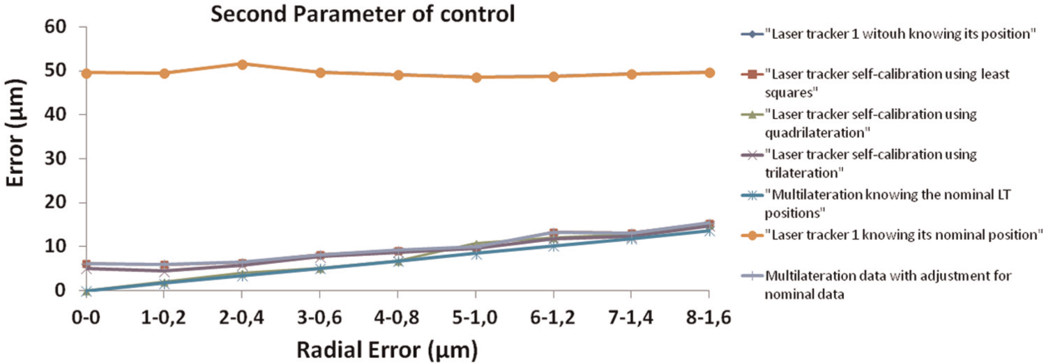
Second parameter of control in self-calibration tests.
Graphs in Figures 17 and 18 present a comparison of the distance between the points in the different coordinate systems by calculating the distances to all the points between them (section ‘Parameters of control’), using different multilateration techniques to obtain the verification points and getting the best LT self-calibration techniques.
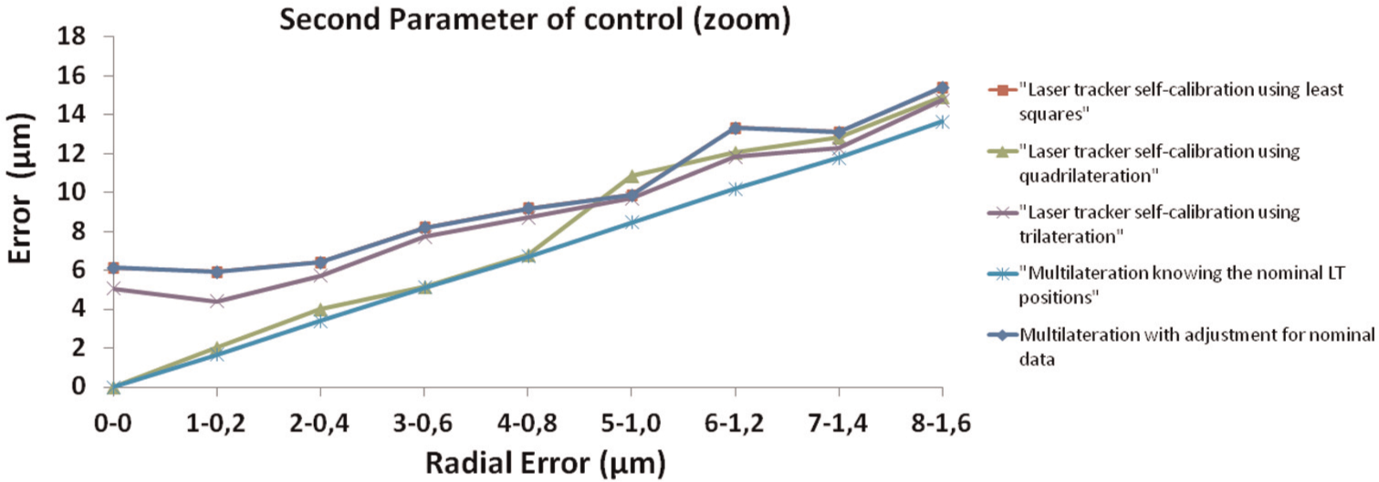
Second parameter of control in self-calibration tests (zoom).
The best self-calibration technique for obtaining the relative positions of the LTs with respect to the nominal positions is quadrilateration (green line in Figure 18). Unlike what occurred with the first control parameter, the error achieved using self-calibration by quadrilateration was greater than that obtained with the nominal positions of the LTs. This finding proves that the improvement in the first control parameter was the result of the subsequent application of a least squares adjustment.
Conclusion
Of all the sources of random errors that affect the LT measurements, the greatest contribution to measurement uncertainty is produced by measurement noise. To reduce the effect of measurement noise, applying a multilateration technique is required.
The uncertainty of the angular encoders was greatly eliminated by applying multilateration. However, the radial measurement uncertainty increased the ve by a greater proportion than the increase in the radial error for the same LT positions. However, the final ve was increased when an increase in the radial noise occurred regardless of the distance between the LT and the measured point. In conclusion, the randomness of volumetric verification optimisation is more influential on the final ve than on the distance between the LTs and the MT workspace.
Similarly, different techniques of LT self-calibration were presented to obtain the LT positions. Quadrilateration and trilateration were better than the least squares with regard to fitness. However, quadrilateration and trilateration depended on the optimisation’s initial values. The result of the synthetic test demonstrated that quadrilateration is the best technique for LT self-calibration, especially when the radial measurement noise is small. Quadrilateration for high and low radial noise deviated from the nominal error by approximately 10%−15% for the second parameter of control and by 8% for the first one. The trilateration deviates from the nominal value setting to 66% in the first parameter control, 90% in the second for low radio noise, and 6% and 11% for high radio noise respectively. This behaviour is similar to that obtained using a least square adjustment. Errors of approximately 170% and 130% were obtained for the first and second parameters of control, respectively, when the radial noise was low, and errors of 32% and 18% were obtained, respectively, when the radial noise was high.
This article presents the sources of error that affect LT measurements and the techniques, scopes and procedure to obtain measured points with less influence of measurement points. From which, volumetric verification should be realised in order to improve its geometrical error characterisation.
Footnotes
Declaration of conflicting interests
The authors declare that there is no conflict of interest.
Funding
This work was supported by the project DICON – Development of new advanced systems of Dimensional Control in manufacturing processes for high-impact sectors (INNPACTO BOE-A-2011-5824).