
Abstract
A calibration method of a hexaglide parallel manipulator is presented to improve its accuracy. A prototype of the hexaglide parallel manipulator is first proposed and its kinematics is analyzed. Through differentiating kinematic equations, 54 geometric error parameters are generated to present the pose error of the moving platform, on which an iterative algorithm for the calibration is based. The experiment starts with the data acquisition. All of measuring poses are newly selected based on the orthogonal design, and the deviations in each pose are measured by a laser tracker. Subsequently, 54 actual geometric parameters are identified by least squares method and compensated to the nominal kinematic model, which is assessed by 25 configurations to obtain the accuracy of the calibrated hexaglide parallel manipulator. It is discovered that the pose errors of the calibrated hexaglide parallel manipulator are significantly reduced and illustrate the validity of the calibration method to improve its accuracy. Finally, we discussed the feasibility of implementing this method in high-accuracy calibration of variant-scale parallel mechanisms.
Introduction
Besides the well-known Gough–Stewart platform, the hexaglide parallel manipulator (HPM) is another popular type of 6-degree-of-freedom (DOF) parallel mechanism, which is constructed by six prismatic-universal-spherical (PUS) parallel kinematic limbs. 1 Its six actuators are all positioned on the fixed base, which significantly relieves the inertia effect of the end-effector and improves its dynamic characteristics. Many achievements with respect to HPMs have been presented,2–5 and their positioning accuracy is often the emphasis among them.
The ultimate accuracy of the HPMs will be inevitably affected due to the existing errors in the processing and assembling, which is also known as geometric parameter errors. 6 This influence can be minimized by kinematic calibration and compensation, which mainly contains four steps: system modeling, error measurement, parameter identification and error compensation.7,8 Among them, the accuracy of error measurement will directly influence the final accuracy of a calibration. A laser tracker is the typical external measuring device used in the calibration to improve the mechanism accuracy and especially suitable for a mechanism with spatially moving freedoms due to its three-dimensional (3D) tracking capability.9,10 Researches on calibration of parallel mechanisms using laser tracker have been widely reported,6,10–12 but few are with respect to the HPMs.
Besides using the laser tracker, scholars focused on calibrating the HPM by other measuring devices and related papers have been published. Ryu and Cha 13 established a comprehensive volumetric error model related to all geometric errors and optimized the design to achieve the required accuracy of end-effector. Rauf et al. 14 designed a device to measure the pose error of the end-effector, and its translational and rotational errors were decreased to less than 2 mm and 1°, respectively. Gong et al. 15 presented an error compensation method considering the elastic deformation and the clearance between the joints. Abtahi et al.16,17 proposed a calibration method based on the relative measurement and simplified the measuring equipment using only three gauges, but the error model only consisted of 42 parameters omitting the orientation errors of each rail, and its maximum positioning error reached to around 1 mm. Ota et al. 18 proceeded a calibration for the HPM by a double ball bar (DBB) and obtained a positioning accuracy of 0.029 mm, but using the DBB is less flexible than using laser trackers to calibrate variant-scale parallel mechanisms. Reviewing these literatures, we reveal that the calibration of the HPM by laser trackers, which improves the positioning accuracy of the HPM to less than 0.03 mm, is rarely reported.
Another issue in the measurement, besides measuring devices, is the measuring pose selection, because the accuracy of an end-effector is differently influenced by its geometric errors in various poses. 19 Many scholars dedicate to optimizing the process of selecting poses to improve the final accuracy of a calibration,20–22 but its effect is still controversial23,24 and optimizing the pose selection makes the calibration complex. To best represent the diverse relationship between the geometric error and the pose error of the end-effector in different configurations, actuating it to reach each pose in its 6-DOF workspace is obviously effective, but it is time-consuming and impractical. Therefore, a practical method to select poses to represent the characteristics of all poses in 6-DOF workspace is significantly required. The orthogonal design, which has been widely used in the manufacturing,25–27 is an effective way to deal with multi-factor experimental designs. The critical benefit of orthogonal design is that we can evaluate characteristics of large samples that are generated by the method of exhaustion with far fewer experimental units. The selected sample by the orthogonal design best represents the whole samples to be evaluated. Applying the orthogonal design to select poses in calibration process is rarely reported.
In this article, a calibration method of a proposed HPM by a laser tracker was presented. A prototype of the HPM was first proposed with its architecture description and coordinate establishment. Based on its kinematic analysis, its 54-parameter error model, which represents all geometric errors, 14 was established by differential method. An iterative calibration algorithm was subsequently designed, and the measuring poses selection based on the orthogonal design was originally proposed in the calibration process. Finally, a calibration experiment for the HPM was proceeded, and a Leica laser tracker was implemented to acquire the 6-DOF pose errors in each selected configuration. According to the proposed algorithm, the geometric errors were identified by the least squares method and utilized to compensate the nominal geometric parameters. Moreover, the pose errors of moving platform before and after compensation were compared in another 25 configurations to evaluate the effectiveness of the calibration and compensation.
Architectural description and inverse kinematics
The proposed HPM has a 6-PUS parallel mechanism, as depicted in Figure 1, which consists of a fixed base, a moving platform and six electric servo-motor-driven limbs; each limb includes a linear actuation, a universal joint, a length-fixed linkage, a uniaxial force sensor and a spherical joint. A servo motor connected with a ball screw is implemented as a prismatic joint in the linear actuation; two guide rails are fabricated to guaranty the linear motion of the slider that is fixed with the nut of the screw. The spherical joint is composed of three revolute joints whose rotation axes are non-coplanar; this structure aims to eliminate the clearance existed in socked-and-ball joints without introducing considerable friction. The fixed base has three slopes distributed symmetrically, and two linear actuations are parallelly arranged on each slope at given intervals.
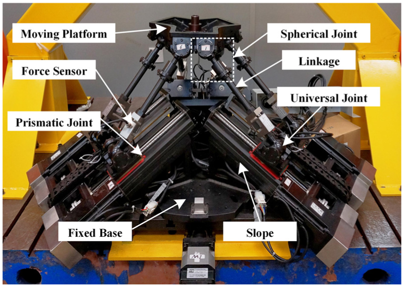
Prototype of the HPM.
In each limb, as shown in Figure 2,
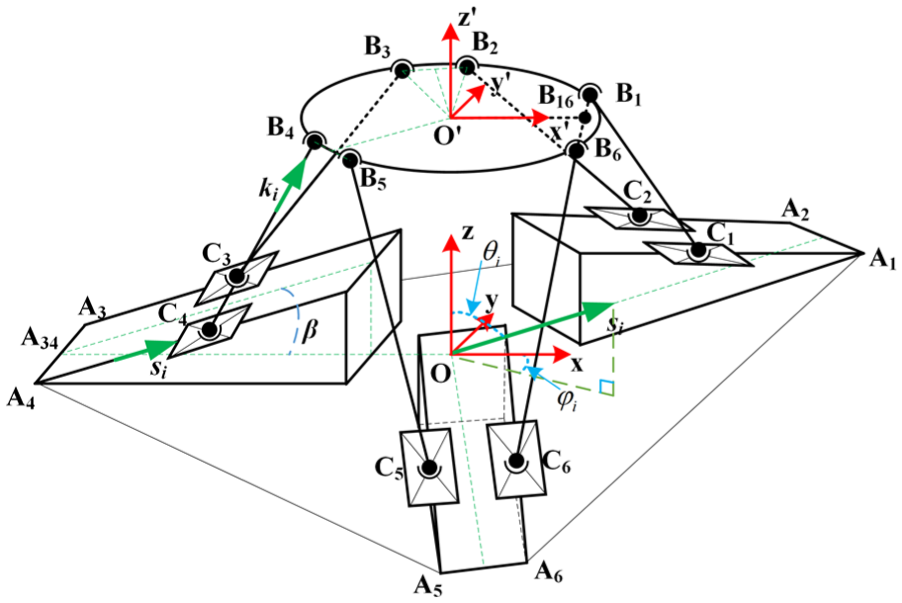
Frame diagram and coordinate definition.
Let us define a configuration of the HPM as
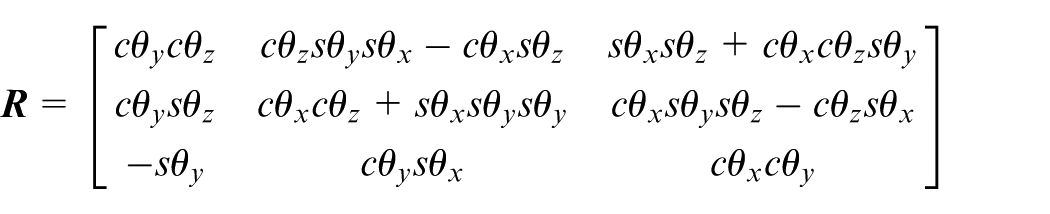
where s and c represent the sine and cosine functions, for example,

where


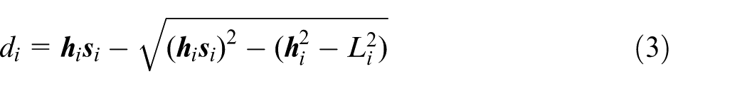
Therefore, the actuation
Error modeling
Expressing equation (1) in terms of small perturbations, we have
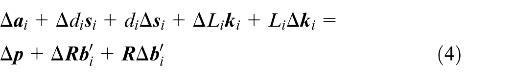
where
Since the displacement of the linear actuation in each limb is measured by an integrated grating sensor whose accuracy is 1 µm and is closed-loop controlled by feeding back the measured positions, the repeatability of the linear actuation measured is less than 1 µm. We omit the actuation error,

Differentiating equation (5), we derive
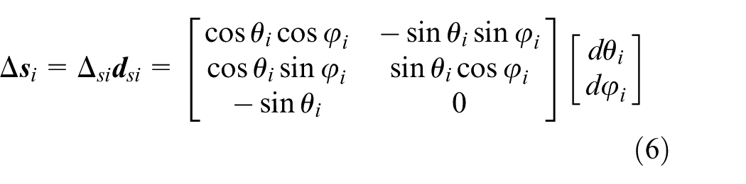
Define

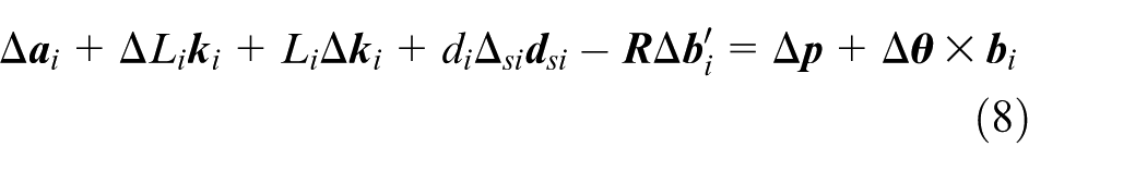
Substituting equations (6) and (7) into equation (4), the error model of the HPM can be established as
Multiplying
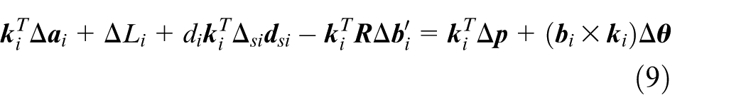
where the position and orientation errors
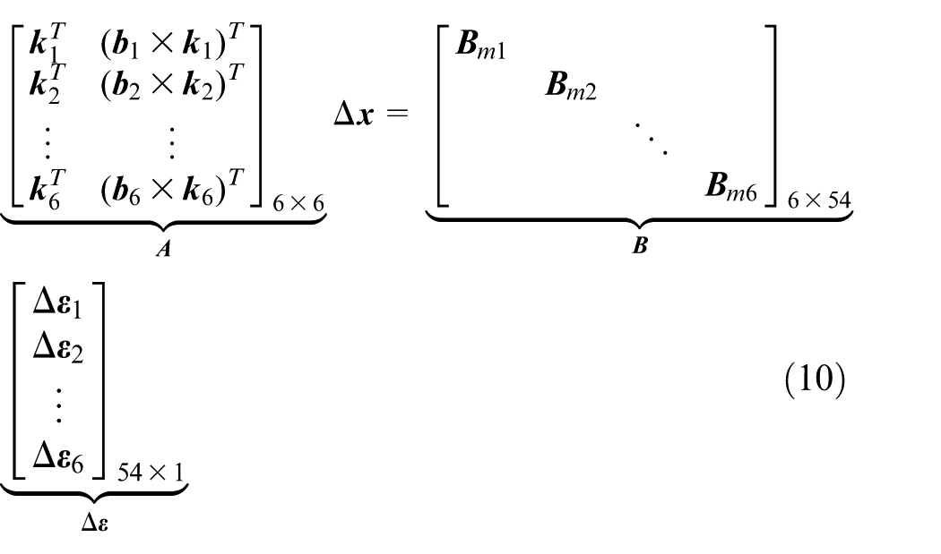
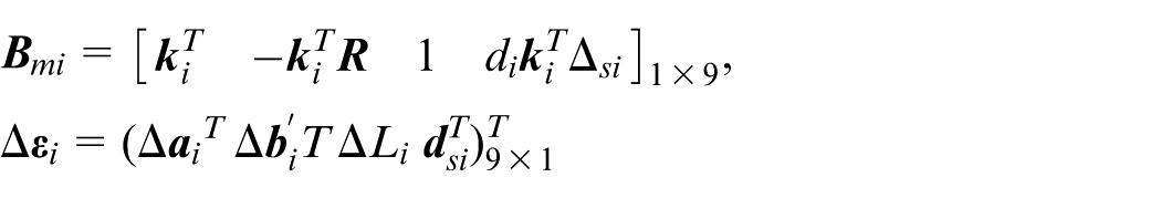
Rearranging equation (9), we obtain

where
Calibration method of the HPM
Iterative algorithm
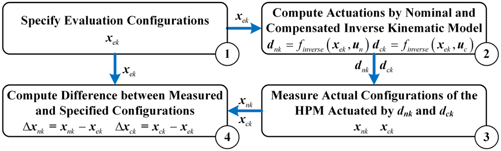
By analyzing the difference between the computed and the actual poses of the HPM with the same actuations
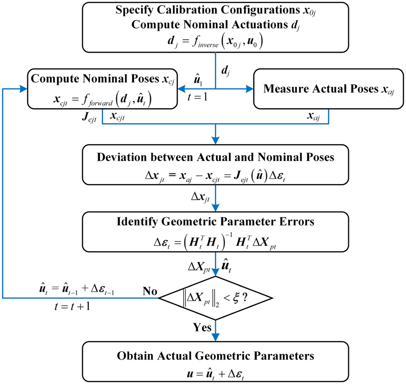
Iterative calibration procedure.
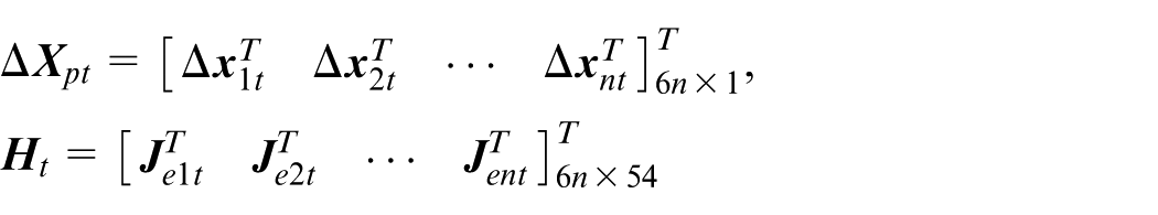
First, the selected calibration poses are specified as

where n is the number of measuring configurations, and the
Second, the computed and measured poses of the HPM actuated by the same


where
Third, due to the geometric parameter error resulting from the inevitable manufacturing and assembling error, the deviation between the computed and the actual poses exists and can be generated as

where
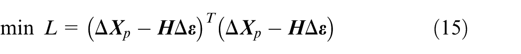
Finally, the geometric parameter error
Then, if the
Meanwhile, the norm of pose error vector
Data acquisition
Orthogonal design for selecting measuring poses
The geometric errors do not vary with the configurations of the HPM, but the latter ones result in their different influence to the position and orientation accuracy.
19
Therefore, to comprehensively discover the pose errors due to the geometric parameters, it is reasonable to specify the calibration poses covering the whole 6-DOF workspace, which will be extremely time-consuming. But the orthogonal design, a mathematic methodology to arrange multi-level and multi-factor experiments,
25
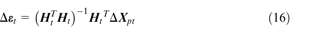
provides an efficient method to select the calibration poses. For example, we divided each DOF into eight levels, as shown in Table 1, so the amount of possible poses derived by the method of exhaustion in the 6-DOF workspace is
Factors and levels of orthogonal design
The orthogonal design table
Coordinate system assignment
There are two calibration coordinates, including a moving fame
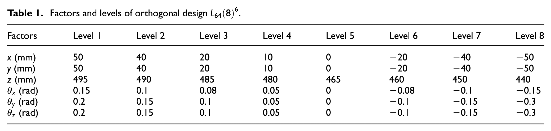
The moving calibration coordinate was established as expressed in Figure 4. There are three circularly distributed holes
Establishment of moving calibration coordinate.
As shown in Figure 5(a), the fixed calibration coordinate was set up. Similarly, there are four prepared holes on the fixed base and symmetrically about the base center.
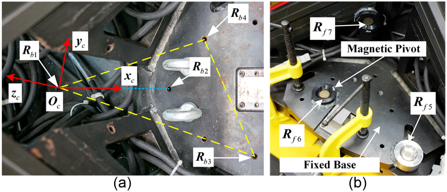
Fixed calibration coordinate.
Through the two coordinates, the relative pose of the moving calibration frame with respect to the fixed one can be accordingly generated in each calibration pose, which is considered as the actual pose of moving platform in the algorithm. Thus, in each calibration pose, the seven reference points,
Calibration experiment
To verify the proposed method, calibration experiments were performed on the HPM (see Figure 6). The measuring distance of the Leica laser tracker was set at 1.5 m to ensure its stability and measuring accuracy. Meanwhile, three reference points
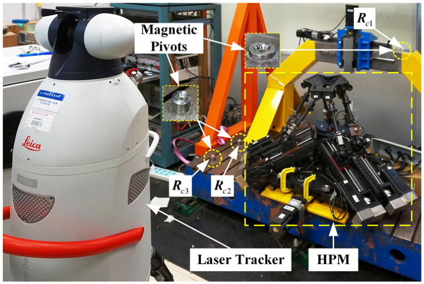
Experimental setup.
Actual geometric parameters.
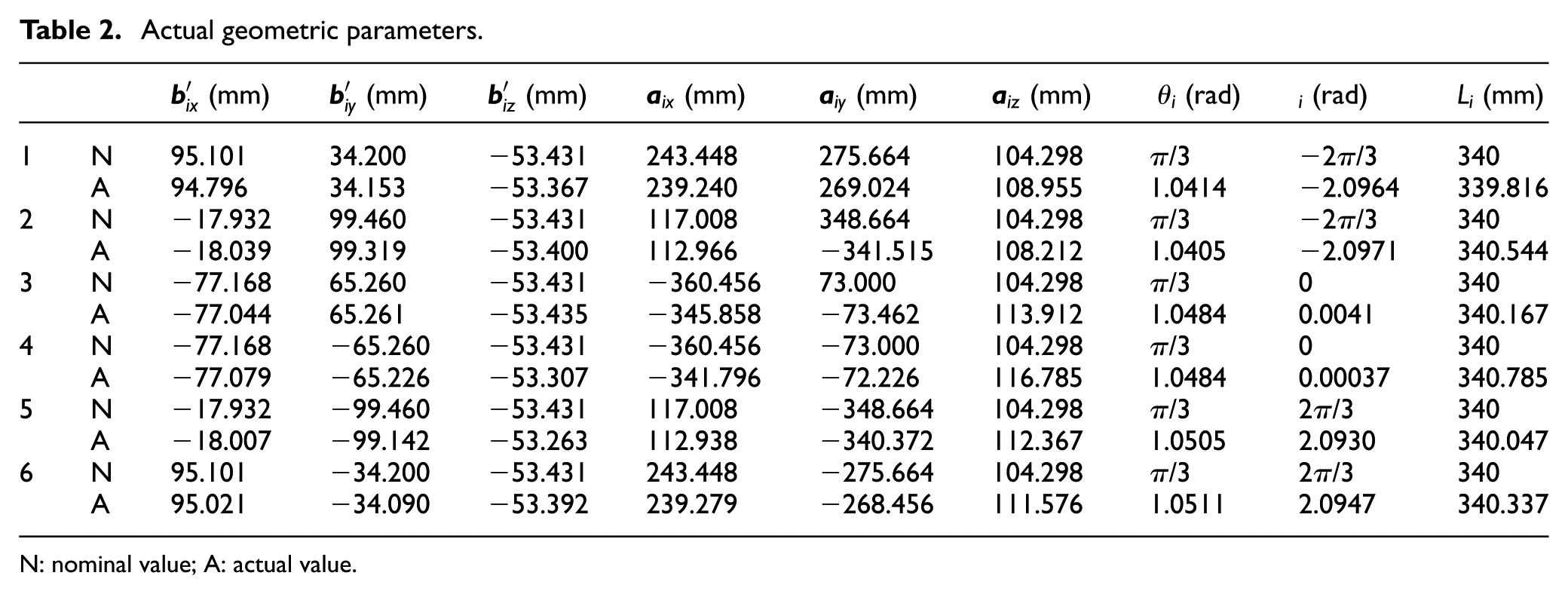
N: nominal value; A: actual value.
It is revealed that all the geometric parameters are identified. Among them, the actual values of
These 54 identified geometric parameters were then utilized to accordingly substitute the nominal parameters in the inverse kinematic model to compensate it, which will decrease the pose errors resulting from the deviation between the nominal and actual kinematics. To evaluate the accuracy of the HPM, it will be actually actuated by the compensated kinematic model and its pose errors will be measured and compared with those actuated by nominal kinematic model in the next section.
Calibration evaluation
To evaluate the calibration and analyze the accuracy of the HPM, as presented in Figure 7, the moving platform of the HPM will be actuated to 25 specified configurations containing three translational and three rotational components (
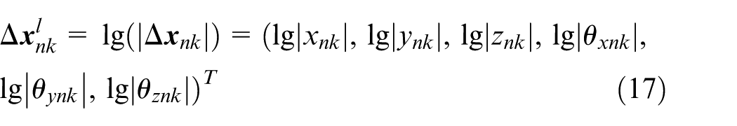
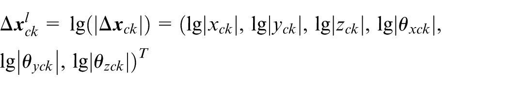
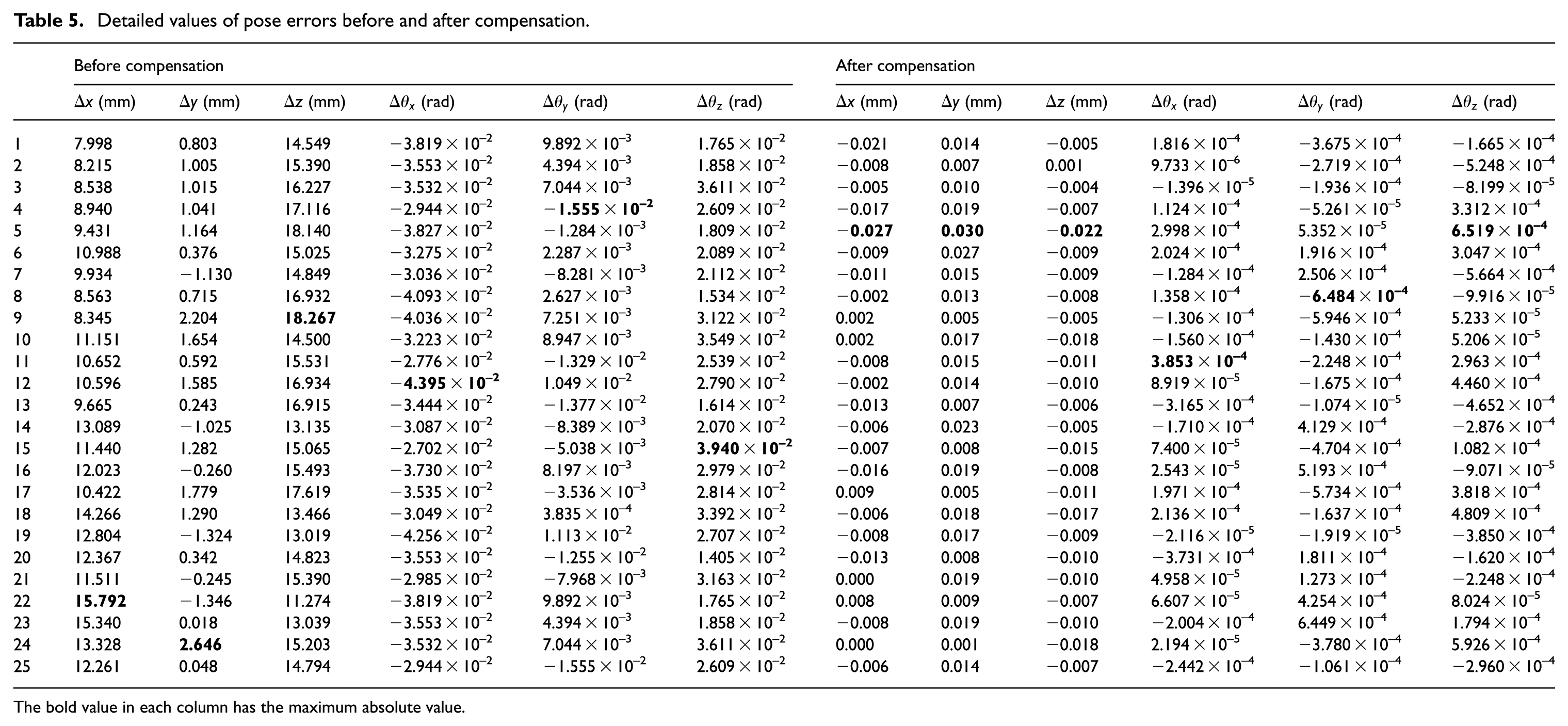
where the superscript l represents the logarithm. The detailed values of the pose errors are summarized in Appendix Table 5, meanwhile those with maximum magnitude in each component of evaluation configurations are shown in Table 3.
Flowchart of evaluating calibration.
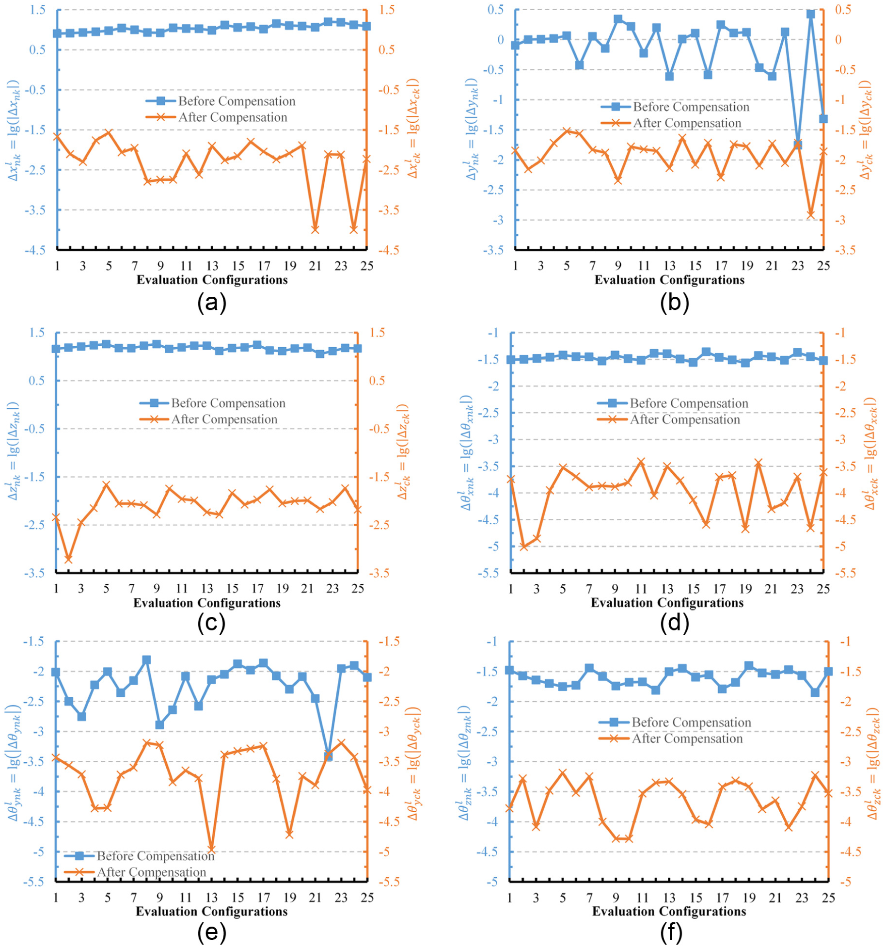
Pose errors compared before and after compensation: (a) logarithm of position error along x-axis, (b) logarithm of position error along y-axis, (c) logarithm of position error along z-axis, (d) logarithm of orientation error about x-axis, (e) logarithm of orientation error about y-axis and (f) logarithm of orientation error about z-axis.
Maximum pose errors before and after compensation.
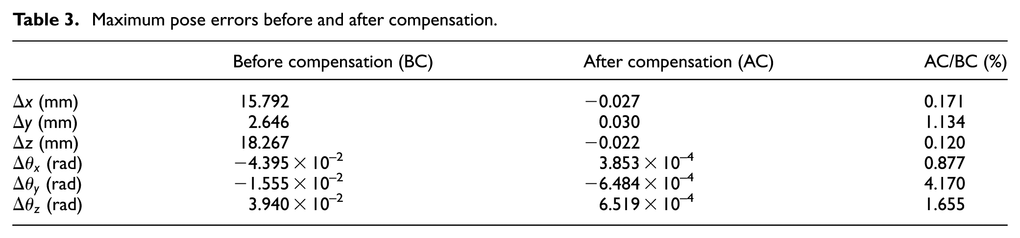
From Figure 8 and Table 3, it is shown that all the six components of poses errors in 25 evaluation configurations are significantly decreased by the calibration and compensation, and these errors before compensation are mostly 10 times as large as those after compensation due to the geometric errors. After the compensation, the maximum translational and rotational errors of the moving platform are 0.03 mm along y-axis and
Discussions
As the typical external measuring device, the laser tracker is often utilized to detect the mechanism accuracy due to its large measuring scale and flexible application. Although the measuring error of the Leica laser tracker is 0.015 mm, which is more than 10 times as large as that of the DBB (0.001 mm), it can still reduce the error of the HPM to 0.03 mm, approaching the results via DBB (0.029 mm), reported by of HexaM. 18 Therefore, the laser tracker has the capability to be implemented in the high-accuracy calibration for variant-scale parallel mechanisms.
Conclusion
A calibration method of the HPM, using the laser tracker, is presented to effectively improve its accuracy. At first, a prototype of the HPM is proposed and its kinematics is analyzed. Its error model is then derived by differentiating the kinematics, and 54 geometric error parameters are generated to present the pose error of its moving platform. The calibration experiment is subsequently established after designing an iterative algorithm.
Calibration poses are selected based on the
To evaluate the accuracy of the HPM, 25 evaluation configurations are specified based on orthogonal design. The maximum translational and orientation errors of the moving platform are 0.03 mm and
Finally, the accuracy of the HPM is compared with a reported same-type machine tool calibrated by the DBB, and the similar accuracy after calibration approves that implementing laser trackers in high-accuracy calibrations is feasible and effective.
Footnotes
Appendix 1
Detailed values of pose errors before and after compensation.
| Before compensation |
After compensation |
|||||||||||
|---|---|---|---|---|---|---|---|---|---|---|---|---|
|
|
|
|
|
|
|
|
|
|
|
|
|
|
| 1 | 7.998 | 0.803 | 14.549 | −3.819×10⁻² | 9.892×10⁻³ | 1.765×10⁻² | −0.021 | 0.014 | −0.005 | 1.816×10⁻⁴ | −3.675×10⁻⁴ | −1.665×10⁻⁴ |
| 2 | 8.215 | 1.005 | 15.390 | −3.553×10⁻² | 4.394×10⁻³ | 1.858×10⁻² | −0.008 | 0.007 | 0.001 | 9.733×10⁻⁶ | −2.719×10⁻⁴ | −5.248×10⁻⁴ |
| 3 | 8.538 | 1.015 | 16.227 | −3.532×10⁻² | 7.044×10⁻³ | 3.611×10⁻² | −0.005 | 0.010 | −0.004 | −1.396×10⁻⁵ | −1.936×10⁻⁴ | −8.199×10⁻⁵ |
| 4 | 8.940 | 1.041 | 17.116 | −2.944×10⁻² | − |
2.609×10⁻² | −0.017 | 0.019 | −0.007 | 1.124×10⁻⁴ | −5.261×10⁻⁵ | 3.312×10⁻⁴ |
| 5 | 9.431 | 1.164 | 18.140 | −3.827×10⁻² | −1.284×10⁻³ | 1.809×10⁻² | − |
|
− |
2.998×10⁻⁴ | 5.352×10⁻⁵ |
|
| 6 | 10.988 | 0.376 | 15.025 | −3.275×10⁻² | 2.287×10⁻³ | 2.089×10⁻² | −0.009 | 0.027 | −0.009 | 2.024×10⁻⁴ | 1.916×10⁻⁴ | 3.047×10⁻⁴ |
| 7 | 9.934 | −1.130 | 14.849 | −3.036×10⁻² | −8.281×10⁻³ | 2.112×10⁻² | −0.011 | 0.015 | −0.009 | −1.284×10⁻⁴ | 2.506×10⁻⁴ | −5.664×10⁻⁴ |
| 8 | 8.563 | 0.715 | 16.932 | −4.093×10⁻² | 2.627×10⁻³ | 1.534×10⁻² | −0.002 | 0.013 | −0.008 | 1.358×10⁻⁴ | − |
−9.916×10⁻⁵ |
| 9 | 8.345 | 2.204 |
|
−4.036×10⁻² | 7.251×10⁻³ | 3.122×10⁻² | 0.002 | 0.005 | −0.005 | −1.306×10⁻⁴ | −5.946×10⁻⁴ | 5.233×10⁻⁵ |
| 10 | 11.151 | 1.654 | 14.500 | −3.223×10⁻² | 8.947×10⁻³ | 3.549×10⁻² | 0.002 | 0.017 | −0.018 | −1.560×10⁻⁴ | −1.430×10⁻⁴ | 5.206×10⁻⁵ |
| 11 | 10.652 | 0.592 | 15.531 | −2.776×10⁻² | −1.329×10⁻² | 2.539×10⁻² | −0.008 | 0.015 | −0.011 |
|
−2.248×10⁻⁴ | 2.963×10⁻⁴ |
| 12 | 10.596 | 1.585 | 16.934 | − |
1.049×10⁻² | 2.790×10⁻² | −0.002 | 0.014 | −0.010 | 8.919×10⁻⁵ | −1.675×10⁻⁴ | 4.460×10⁻⁴ |
| 13 | 9.665 | 0.243 | 16.915 | −3.444×10⁻² | −1.377×10⁻² | 1.614×10⁻² | −0.013 | 0.007 | −0.006 | −3.165×10⁻⁴ | −1.074×10⁻⁵ | −4.652×10⁻⁴ |
| 14 | 13.089 | −1.025 | 13.135 | −3.087×10⁻² | −8.389×10⁻³ | 2.070×10⁻² | −0.006 | 0.023 | −0.005 | −1.710×10⁻⁴ | 4.129×10⁻⁴ | −2.876×10⁻⁴ |
| 15 | 11.440 | 1.282 | 15.065 | −2.702×10⁻² | −5.038×10⁻³ |
|
−0.007 | 0.008 | −0.015 | 7.400×10⁻⁵ | −4.704×10⁻⁴ | 1.082×10⁻⁴ |
| 16 | 12.023 | −0.260 | 15.493 | −3.730×10⁻² | 8.197×10⁻³ | 2.979×10⁻² | −0.016 | 0.019 | −0.008 | 2.543×10⁻⁵ | 5.193×10⁻⁴ | −9.071×10⁻⁵ |
| 17 | 10.422 | 1.779 | 17.619 | −3.535×10⁻² | −3.536×10⁻³ | 2.814×10⁻² | 0.009 | 0.005 | −0.011 | 1.971×10⁻⁴ | −5.734×10⁻⁴ | 3.818×10⁻⁴ |
| 18 | 14.266 | 1.290 | 13.466 | −3.049×10⁻² | 3.835×10⁻⁴ | 3.392×10⁻² | −0.006 | 0.018 | −0.017 | 2.136×10⁻⁴ | −1.637×10⁻⁴ | 4.809×10⁻⁴ |
| 19 | 12.804 | −1.324 | 13.019 | −4.256×10⁻² | 1.113×10⁻² | 2.707×10⁻² | −0.008 | 0.017 | −0.009 | −2.116×10⁻⁵ | −1.919×10⁻⁵ | −3.850×10⁻⁴ |
| 20 | 12.367 | 0.342 | 14.823 | −3.553×10⁻² | −1.255×10⁻² | 1.405×10⁻² | −0.013 | 0.008 | −0.010 | −3.731×10⁻⁴ | 1.811×10⁻⁴ | −1.620×10⁻⁴ |
| 21 | 11.511 | −0.245 | 15.390 | −2.985×10⁻² | −7.968×10⁻³ | 3.163×10⁻² | 0.000 | 0.019 | −0.010 | 4.958×10⁻⁵ | 1.273×10⁻⁴ | −2.248×10⁻⁴ |
| 22 |
|
−1.346 | 11.274 | −3.819×10⁻² | 9.892×10⁻³ | 1.765×10⁻² | 0.008 | 0.009 | −0.007 | 6.607×10⁻⁵ | 4.254×10⁻⁴ | 8.024×10⁻⁵ |
| 23 | 15.340 | 0.018 | 13.039 | −3.553×10⁻² | 4.394×10⁻³ | 1.858×10⁻² | −0.008 | 0.019 | −0.010 | −2.004×10⁻⁴ | 6.449×10⁻⁴ | 1.794×10⁻⁴ |
| 24 | 13.328 |
|
15.203 | −3.532×10⁻² | 7.044×10⁻³ | 3.611×10⁻² | 0.000 | 0.001 | −0.018 | 2.194×10⁻⁵ | −3.780×10⁻⁴ | 5.926×10⁻⁴ |
| 25 | 12.261 | 0.048 | 14.794 | −2.944×10⁻² | −1.555×10⁻² | 2.609×10⁻² | −0.006 | 0.014 | −0.007 | −2.442×10⁻⁴ | −1.061×10⁻⁴ | −2.960×10⁻⁴ |
The bold value in each column has the maximum absolute value.
Declaration of conflicting interests
The author(s) declared no potential conflicts of interest with respect to the research, authorship and/or publication of this article.
Funding
The author(s) disclosed receipt of the following financial support for the research, authorship, and/or publication of this article: This work was supported by the National Natural Science Foundation of China (Grant No. 51305013).