
Abstract
Calibration of robot kinematic parameters can effectively improve the absolute positioning accuracy of the end-effector for industrial robots. This article proposes a calibration method for robot kinematic parameters based on the drawstring displacement sensor. Firstly, the kinematic error model for articulated robot is established. Based on such a model, the position measurement system consisting of four drawstring displacement sensors is used to measure the actual position of the robot end-effector. Then, the deviation of the kinematic parameters of the robot is identified by the least-squares method according to robot end-effector deviations. The Cartesian space compensation method is adopted to improve the absolute positioning accuracy of the robot end-effecter. By experiments on the EFORT ER3A robot, the absolute positioning accuracy of the robot is significantly improved after calibration, which shows the effectiveness of the proposed method.
Keywords
Introduction
In recent years, with the continuous development of the robot industry in China, the application range of robots has become more and more extensive. Domestic industrial robots are increasingly applied to some complicated manufacturing industries, and the performance requirements for domestic robots are getting higher and higher. Accuracy is one of the important indicators to measure the performance of robots. 1 In many aspects of robot applications such as off-line programming, visual servo, and laser cutting, robots need high absolute positioning accuracy.
At present, the positioning accuracy of industrial robots is improved mainly by the kinematic calibration of industrial robots. 2 The kinematic calibration of industrial robots generally includes the following four aspects: modeling, measurement, parameter identification, and compensation. 3 A lot of researches have been done on the kinematic calibration of robots at home and abroad, and a large number of robot kinematic model establishment methods 4 –8 and parameter identification algorithms have been proposed, but most of the researchers still use the laser tracker 9 –11 measuring the actual position of the robot’s end-effectors. Because the laser tracker has high requirements on environmental factors such as temperature, humidity, and dust during application, it is quite difficult to use widely in domestic small and medium-sized robot manufacturing enterprises due to its high price and environmental requirements.
To reduce the calibration cost and effectively improve the absolute positioning accuracy of the robot, a robust and low-cost calibration method of the kinematic parameters for articulated robot through the drawstring displacement sensor is proposed in this article. In this article, the robot theoretical kinematic parameters are provided by robot manufacturers, the theoretical Modified Denavit–Hartenberg (MDH) model 12 can be used to overcome the defects of the D-H model when adjacent joints are parallel. Based on the MDH model, the theoretical position of the robot end-effector can be calculated. The robot end-effector position measurement system consisting of four drawstring displacement sensors is used to measure the actual position of the robot end-effector. Thereafter, the desired position of the robot end-effector and the differential error model of the robot are used to identify the deviations by least-squares method. Finally, the kinematic parameter deviations of the robot are compensated by the Cartesian space compensation method to improve the absolute positioning accuracy of the robot.
The remaining of this article is organized as follows. The principle of robot kinematic parameter calibration is introduced in the second section. A robust and low-cost approach of robot end-effector measurement is proposed in the third section. Robot kinematic parameter identification and error compensation is presented in the fourth section. Experiments are carried out in the fifth section, followed by conclusions in the sixth section.
The principle of robot kinematic parameter calibration
Robot differential motion model
The robot joint coordinate system transformation between adjacent joints includes translation transformation and rotation transformation. The differential kinematic of the robot is to perform a small amount of translation transformation and rotation transformation, which can be called differential translation transformation and differential rotation transformation. The differential translation transformation has a slight translational change in the direction of the three coordinate axes of the original robot joint coordinate system, which can be represented as follows

The differential rotation transformation has a slight rotation change on the three coordinate axes of the original robot joint coordinate system. This transformation is equivalent to the original coordinate around a fixed vector
Here, the differential equation of the trigonometric function is considered and it satisfies
Therefore, the differential rotation equation around the x-axis is as shown in the following equation
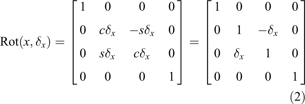
where
Similarly, a differential rotation equation around the y-axis and the z-axis can be obtained. For the differential equation of motion, when the higher-order differential term is ignored, the differential motion transform is not related to the multiplication order of the matrix, so that the differential rotation equation around a fixed vector in space can be obtained, as shown in the following equation

Then, the differential transformation operator of the robot coordinate system can be obtained as shown in the following equation

Error model of robot kinematics
The robot kinematics is modeled according to the MDH modeling method. On the basis of the D-H model, the rotation term
11
around the y-axis is added, that means the torsion angle

where the four quantities
According to the principle of differentiation calculation, the two end-effector of the transfer matrix between adjacent link coordinate systems are differentiated to obtain
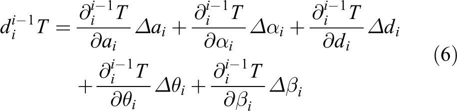
where


According to equation (7) to equation (11), equation (6) can be transformed into
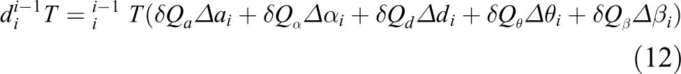
Here, we define that a differential transformation operator matrix

Substituting equation (7) to equation (11) into equation (13) yields

in which


According to equation (15) to equation (20), the robot end-effector pose error caused by the kinematic parameter errors of the robot can be represented as


Substituting the error matrix

where

The robot end-effector pose error matrix is reformed, in which the deviation between the actual position and the desired position of the robot end is equal to the robot end position error calculated according to the robot kinematic parameter deviation, therefore relationship between the robot end position deviation and the robot kinematic parameter deviation can be obtained. The constraint relationship between them can be presented as

in which dn
is the deviation value of the robot end-effector position, Ma
,
Method of robot end-effector pose measurement
In this article, the actual position of the robot end-effector is measured by a low-cost measuring system consisting of four drawstring displacement sensors. This measuring system mainly consists of three parts: the base, the drawstring displacement sensor, and the universal joint at the end of the robot. The position measuring system mainly converts the position data of one point in the space into the length data of the drawstring displacement sensor. The three-dimensional model of the position measurement system is shown in Figure 1.

The 3-D schematic model of position measuring system by drawstring displacement sensors.
A simplified schematic model of the proposed position measuring system by drawstring displacement sensors in Figure 1 is shown in Figure 2. A, B, C, and D are the fixed positions of the four drawstring displacement sensors like the sensor home position. Before measuring the actual position of the end flange of the robot, it is first necessary to measure the relative distance between the four drawstring displacement sensors. la , lb , lc , and ld are the sensor values of the individual drawstring displacement sensors and r means the distance between the fixed measurement point T of the robot end universal joint and the measuring ends of the four drawstring displacement sensors. The coordinate system of the position measurement system is established at point A, where A is the origin of the coordinate system, the direction of AC is the X-axis direction of the measuring sensor coordinate system, the Z-axis direction is the normal direction of the plane ABCD, and the Y-axis direction is determined by the right-hand rule.

The schematic model of position measuring system by drawstring displacement sensors.
Assume that the position coordinate of the measured point of the robot end flange in the position measuring system coordinate system is (x, y, z), and the values of x, y, and z are calculated by the geometric relationship to determine the position coordinates of the measured point.
In Figure 2, the point C is CE perpendicular to the AC intersection AD and the point E, and the past point C is CF perpendicular to the AC intersection AT at the point F, connecting the EF.
Let the angle between AT and AC be β, then

According to equation (26), the coordinates of the robot end position measurement point can be calculated as follows

Let the angle between AT and AD be α, then

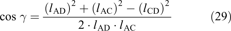
Let the angle between AT and AC be γ, then
Let the angle between AT and ABCD plane be θ, then

Then the distance from the measured point T to the plane ABCD, that is, the z coordinate of the measured point T is

Since CE is perpendicular to AC, the length of CE is

The length of the AE is
Since CF is perpendicular to AC, the length of CF is

The length of the AF is
According to equations (28), (33), and (35), the length of the EF can be obtained as follows

Let the angle between CE and CF be ω, then

According to equations (26) and (30), the coordinates of the measured point y of the robot end flange can be obtained as

By the above equations (27), (31), and (38), the position coordinate (x, y, z) of the measured point of the robot end-effector can be obtained.
Robot kinematic parameter identification and error compensation
Robot kinematic parameters identification
The basic idea of robot kinematic parameter identification is to establish the differential error model of the robot and obtain the constraint relationship between the robot end position deviation and the robot kinematic parameter deviation. According to the measured position between the actual position and the desired position of the robot end-effector, the deviation calculates the kinematic parameter deviation of the robot by equation (25).
The calculation process of robot parameter identification is shown in Figure 3.

Process of robot kinematic parameters identification.
Parameter identification is mainly based on equation (25) to calculate the deviation value of the kinematic parameters of the robot. Equation (25) can be expressed in the form of
If the matrix

Error compensation of robot kinematic parameters
In this article, the Cartesian space compensation method is used to improve the accuracy of the end-effector of the robot. Calculate the pose deviation of the robot at the target position based on the parameter deviation of the kinematic parameters of the robot and the six theoretical joint angles of the robot motion to the target position. After using the desired pose and subtracting the pose deviation, the compensation can be obtained. The pose is solved by the inverse kinematic of the robot based on the compensated pose, and the six joint angles obtained by the solution are given to the robot to move the robot to the desired position. The Cartesian space compensation method is shown in Figure 4.

Error compensation process for robot in Cartesian space.
Experiments
To verify the effectiveness of the proposed method, the vertical six-joint industrial robot ER3A produced by EFORT corporation is used as the experimental subject. The robot position measurement sensor is designed on the robot controller and teach pendant developed by our research group. A PC-based robot controller with EtherCAT interface for servo drive control has been designed in our experiment. An Intel J1900 CPU with VxWorks 6.2 real-time operating system installed has been used as the main robot controller and the EtherCAT communication has been realized by Hilscher Cifx-104-RE communication card. Four drawstring displacement sensors produced by Fritz Kuebler GmbH in Germany have been used in our experiment, whose type number is
Specifications of the Kuebler drawstring displacement sensors


Experiment setup.
In the calibration process of the kinematic parameters of the robot, to effectively improve the absolute positioning accuracy of the robot, the selection of the sampling points of the robot should generally cover the working space of the robot as much as possible. In this article, 50 sampling points are selected in the main working space of the ER3A industrial robot. The actual position of these sampling points is measured by the robot position measuring system. The expected position and actual position of the sampling point are shown in Figure 6. The desired position refers to the expected value calculated according to the kinematic design parameters of the robot and the joint angle. The actual position is the position detected and calculated by our proposed position sensor designed in this article by drawstring displacement sensors.

Desired position and actual position of the sampling point.
In the experiment, 30 points from the 50 sampling points were selected as the experimental data for calculation of the robot kinematic parameter identification, and the remaining 20 sampling points were used as comparison data for the improvement of the positioning error of the robot before and after the calibration. Substitute all these data including the actual position of the calculated 30 sampling points in the robot base coordinate system, the theoretical position of 30 sampling points, the joint angle of each joint corresponding to the sampling points, the theoretical kinematic parameters of the robot, and the robot universal joint dimensions, into the constraint equation (25) and the robot kinematic parameter deviations could be identified. The deviations of the robot kinematic parameters have been identified by the least-squares method as shown in Table 2.
The calibrated result of kinematic parameter deviation for robot ER3A.

According to the kinematic parameter deviation of the robot in Table 2 and the theoretical kinematic parameters of the ER3A robot and the theoretical dimension parameters of the robot universal joint, the Cartesian space compensation method has been used to compensate the error of the end-effector position of the robot. The positioning error of the sampling point, combined with the positioning error of the sampling point of the robot before calibration, and the positioning error of the sampling point of the robot before and after calibration can be obtained as shown in Figure 7.

End-effector position error of the robot ER3A before and after calibration.
According to the positioning error data of the sampling point of the robot before and after calibration (as shown in Tables 3 and 4), the maximum positioning error of the sampling point of the robot in the X-axis direction is reduced from 3.4526 mm to 1.9688 mm, which is reduced by 42.98%; the average positioning error is reduced from 1.4687 mm to 0.8135 mm, which is reduced by 44.61%. The maximum positioning error in the Y-axis direction decreased from 5.3287 mm to 2.1470 mm, which is reduced by 59.71%; the average positioning error decreased from 2.1253 mm to 0.9568 mm, which is reduced by 54.98%. The maximum positioning error in the Z-axis direction is reduced from 4.8554 mm to 1.0063 mm, which is reduced by 79.27%. The average positioning error is reduced from 2.5330 mm to 0.3575 mm, which is reduced by 85.89%. The maximum positioning error of the sampling point of the robot is reduced from 6.7105 mm before calibration to 2.3437 mm after calibration, which is reduced by 65.07%. The average positioning error is reduced from 3.8413 mm to 1.3916 mm after calibration, which is reduced by 63.77%. Through the comparison of the experimental results, the absolute positioning accuracy of the robot can be significantly improved after the kinematic calibration of the industrial robot by our proposed method.
Comparison of the maximum position error for ER3A robot before and after calibration.

Average error of the end-effector position for ER3A robot before and after calibration.

Conclusion
In this article, a calibration method of robot kinematic parameters based on the drawstring displacement sensors is proposed, which can further improve the absolute positioning accuracy of industrial robots. Firstly, based on the differential kinematic model of the robot, the kinematic error model of the robot is established. A low-cost robot position measurement system consisting of four drawstring displacement sensors is used to measure the actual position coordinates of the robot end-effector. Thereafter, according to the theoretical position and actual position of the robot, the deviation between the kinematic parameters of the robot is identified by the least-squares method. The Cartesian space compensation method is used to compensate the robot accuracy according to the identified deviations of the kinematic parameters of the robot, so as to improve the absolute positioning accuracy of the robot. The advantage of the proposed method is that it does not require the expensive laser trackers to measure the position of the robot end-effector, which greatly reduce the cost of robot kinematic calibration. Experiments on the articulated robot ER3A verify the effectiveness of our proposed method.
Footnotes
Declaration of conflicting interests
The author(s) declared no potential conflicts of interest with respect to the research, authorship, and/or publication of this article.
Funding
The author(s) disclosed receipt of the following financial support for the research, authorship, and/or publication of this article: This work was supported in part by the Natural Science Foundation of China under grant nos 61873308, 61503076, and 61175113 and the Natural Science Foundation of Jiangsu Province under grant no. BK20150624.