
Abstract
To solve the problems of poor versatility and inactivity of the traditional interventional catheters, a forward kinematic model of multi-segment catheters in series is established by using D-H parameter method, which is based on the geometrical structure of the designed catheters. In order to ensure the decoupling control of the driver’s length, we look into the relationship between the driver’s length and the posture of the catheter unit. The control model of the catheter’s posture is further presented, in which the characteristics of driver is equivalent to the arc shape. Finally, the fuzzy Proportional-Integral-Differential Control (PID) control is designed to control the catheter unit which greatly improves the precision of the control model. The results show that the relationship between the predicted driver length and the catheter attitude angle is basically consistent with the experimental results, which verifies the effectiveness of the variable universe fuzzy PID control.
Keywords
Introduction
With a surging incidence of cardiovascular diseases, vascular intervention operation, as a safe, efficient, and low-cost mode of operation, has become a key research topic in recent years. 1,2 As the most common tool in interventional surgery, interventional catheters are used for multiple purposes, including discharge of fluids from human body, injection of medicines into the diseased region and conveyance of surgical instruments for incision of the diseased region, bypass surgery, and other operations. Driller utilized the magnetic forces of the winding to drive the surgical interventional catheter into the aorta and its branches. 3 Bergeles and others proposed one new-type active microcatheter driven by Shape Memory Alloy (SMA) spring. Through the control of SMA spring, it is possible to realize movements of the catheter in different directions. 4,5 Bruns realized the complicated attitude control at the end of the catheter through the cooperative control of four traction wires. 6 Volder 7,8 proposed a catheter-oriented robot, with three SMA coil springs distributed between the inner and outer tubes, and a joint for support and connection at regular intervals. Arora and others 9,10 used bellows to design a hydraulic catheter and proposed the control mechanism of “single input multiple output.” This mechanism uses driving fluids as the signal generator to independently control each section of the bellows. This catheter applies a pressure band pass valve to control the pressure of bellows. It consists of a high-pass valve and a low-pass valve. Fu Yili and others 11 proposed one SMA-driven active catheter and conducted a detailed and in-depth theoretical analysis and experiment. Huang Wentai 12 designed one set of master-slave control catheter system which includes a 3-degree of freedom (DOF) main robot Falcon to control the pushing, rotation, and bending of the catheter. Liu Da and other scholars 13 –18 designed one remotely controlled master-slave catheter system which establishes a network data transmission layer linking the master and the salve and acquires the positioning error of the pushing mechanism at different pushing speeds.
The fuzzy PID control method is a good method to improve the performance of the catheter control 19 Its biggest advantage is that it does not only need to know the exact mathematical model of the controlled object but also can adopt fuzzy control technology and make the control system have very good robustness 20 There are many researchers who use fuzzy PID control method for improving system control performance. Savran 21 presented an adaptive strategy based on fuzzy PID controller. By combining the Model Predictive Control (MPC) theory, a control method using fuzzy is derived and applied in the medical equipment to solve the anesthesia injection quantity control and ensure the injected volume at a safe set-point. 22 Based on fuzzy PID method, a new fuzzy MPC method is proposed to solve the temperature control of a power plant. 23 Lu 24 proposed a new method to combine the principle of fuzzy control for controlling the uncertainty and complexity of the time delayed systems. For multi-objective PSO, Chiou 25 proposed a strengthening evolutionary algorithm using a adaptive fuzzy PID controller, however, there is a steady state error. There are many other research results using fuzzy control and predictive control to optimize PID controllers. 26 –31
However, conventional minimally invasive surgery has many weaknesses. Structurally, the conventional interventional surgical catheter’s lack of generality and initiative severely affects the effects of interventional surgery. In control mode, the difficult control and uncertain accuracy of a conventional interventional surgical catheter raise high technical requirements on the operator. In response to the lack of versatility and inactivity of a conventional interventional surgical catheter, this thesis designs one mixed-drive modular interventional surgical catheter, as Figure 1 shows. It comprises one rope-driven active unit and multiple sections of SMA-driven active units connected in series. Various catheter units are connected via a removable flexible structure. Before operation, the operator can choose an appropriate active unit for fast assembly according to the environment of the interventional surgery. The attitude of various catheter units can be controlled via control of the drive rope and SMA spring. Moreover, this structure addresses the problem of coupling of a conventional interventional surgical catheter along the length of the drive and thus increases the control accuracy of the catheter.

Interventional surgical catheter structure. (a) Rope-driven catheter unit. (b) SMA-driven unit. (c) Catheter assembly drawing.
Analysis of motion control of catheter
Kinetic modeling of catheter
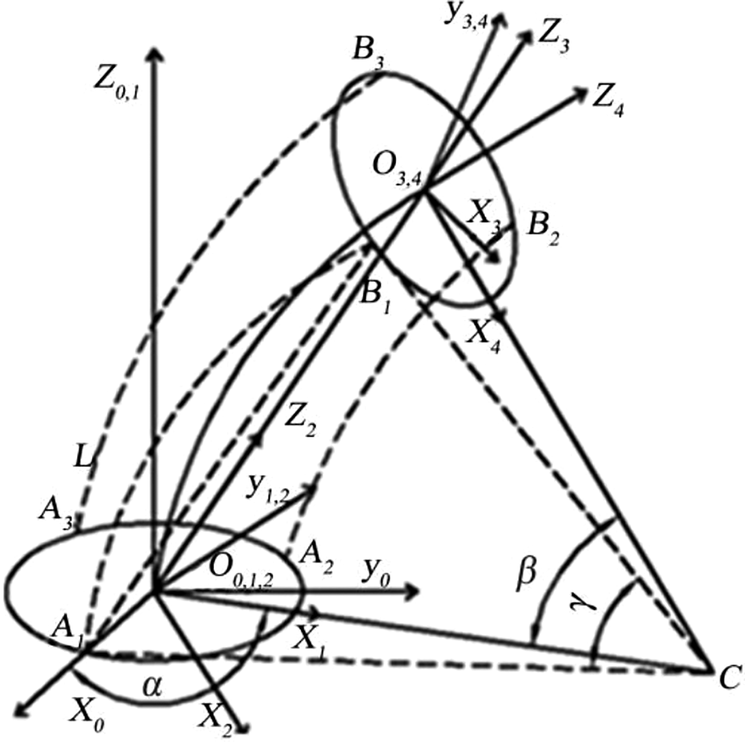
As the robot’s rope-driven active catheter unit and the SMA catheter units have the same DOF, a uniform catheter unit’s forward kinetic model is firstly established in the thesis and then the forward kinetic planning is rapidly conducted according to the quantity of active catheter units in the catheter. The 3-DOF of the catheter, such as pushing, rotation, and bending, is indicated as three variables L, α, and β. {O 0} represents the base coordinate system; {O 5} represents the terminal coordinate system, as Figure 2 shows. The homogeneous transformation matrix between {O 0} and {O 5} can be established in the Denavi-Hartenberg method (D-H) parametric method. 15 The transformation process is shown as follows. The relative position between the terminal coordinate system and the base coordinate system can be determined accordingly.

Two-dimensional diagram of single catheter section.
Assume that the bent section of catheter is close to an arc; the terminal catheter length is L 1; the pushing distance is L; the turning and bending angles are α and β, respectively.
The steps to complete the movement of a catheter unit are: {O
0} moves by L along axis z
0; {O
1} rotates by α clockwise along axis z
1; {O
2} rotates by β/2 clockwise along axis x
2; {O
3} moves by {O
4} rotates by β/2 clockwise along axis x
4;
Where

Multiply various transformation matrixes to obtain the homogeneous transformation matrix between {O0 } and {O5 }

Use coordinate (XT , YT , ZT ) to indicate the position of the end of the catheter unit. The last column of the foregoing transformation matrix can come up with the relations between the position of the end of the catheter unit and catheter length L 1, pushing distance L as well as turning and bending angles α and β

Apply Mathematica software to programming according to the foregoing relations to draw the 3-D movement space of the end of catheter unit. Take a catheter unit of L 1 = 50 mm as an example. Assuming that the push distance L is 0–20 mm, the bending angle β is 0–π/3 and α is 0–2π. L step length is 4 mm; the step length of α and β is π/30. The 3-D drawing of the working space of the end of catheter unit as shown in Figure 3 can be acquired. The figure clearly shows that the catheter’s working space basically takes the shape of a column. Due to the restrictions on catheter bending angle, some regions are inaccessible. Increasing the bending angle of the catheter can increase the accessible working space of the catheter.

Working space of catheter unit.
According to the foregoing process of solving, it is possible to summarize the general kinematic solving method when n active catheter sections are connected in series. Assume that the n catheter section length is Ln and the turning and bending angles are αn and βn , respectively. The transformation matrix from base coordinate system {O 0} to {O 5n } can be acquired

Where the transformation matrix from the n − 1 joint to the end of the n catheter unit

Differentiate the relational expression of the terminal position and the posture of the catheter unit and get
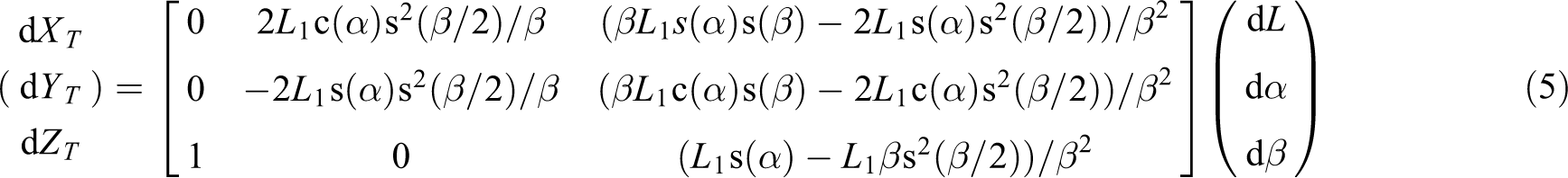
Then the catheter unit Jacobian matrix can be expressed as
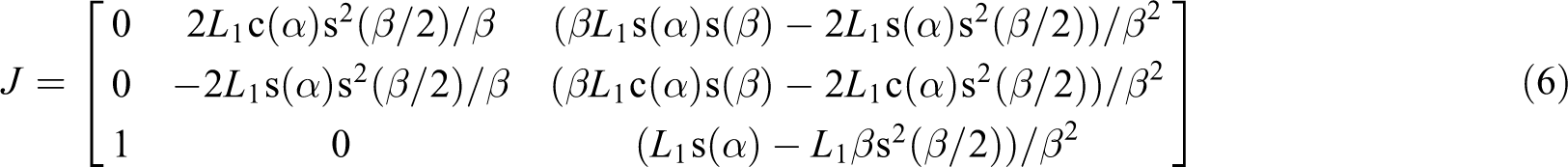
When the Jacobian matrix J is nonsingular matrix, the inverse can be obtained, so that the relationship between the terminal velocity space of the catheter and the joint variable space can be established according to the obtained inverse Jacobian matrix.
In order to determine whether the Jacobian matrix is singular matrix, it can be known from the matrix simplification that

To make |J|=0, it must have

That is, when β = 0 or 2.23, the above equation holds. Due to the limitation of catheter bending Angle, the solution of β = 2.23 is not in the range of catheter bending Angle.
So when β = 0, Jacobian matrix is singular. When β ≠ 0, the Jacobian matrix is nonsingular, and the inverse matrix can be obtained, thus obtaining the joint space velocity expression

Path planning of catheter
In practice, the active catheter must have good flexibility to avoid collision with vascular wall, the protruding part of vascular bifurcation as well as lesion sites. In the article, the path planning of catheter intervention is further studied based on the kinematic modeling of catheter. It is known that the best path of catheter intervention is the trace that moves along the center line of blood vessels. However, it is difficult to move accurately along the ideal path due to the complex environment of vascular cavity in human body. Therefore, the curvature at the vessel, the diameter of the vessel, and the maximum length of the catheter for the whole interventional operation should be taken into account in the path planning of catheter. And the pitch number of interventional catheter, the length of the catheter, and the planning of path can then be determined.
In order to obtain the moving path of the catheter conveniently and quickly, the three-point planning method was used to design the path planning. The bending shape of the catheter was taken as the arc, and the axis length of the catheter will not be changed after bending. For the ith active catheter unit with the diameter of di , the two coordinates of O i −1, O i at the extreme points of the central axis have been established. The coordinate of the middlepoint in the central axis is taken as M i , which is relatived to the basecoordinate system O i−1. The bending angle of the catheter (αi , βi ) and the established coordinate are shown in Figure 4.

Path planning for the ith catheter unit.
To the first intervention catheter unit, the extreme point of the central axis is established with the coordinate of (x 0, y 0, z 0, 1), and the coordinate of O i −1(xi −1, yi −1, zi −1) at the extreme point of the ith catheter can then be written by

where
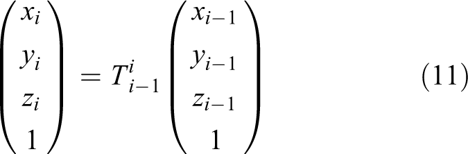
The coordinates of M i (xmi , ymi , zmi ) at the middle point of the ith catheter can be expressed as follows

It can be seen that the coordinate values at the extreme point, end point, and middle point of catheter axis are only related to αi and βi , so the optimum value of the path planning can be obtained in the central axis of vessel as far as possible by using the three-point planning method. The optimal value of bending angle (αi , βi ) at each catheter can be obtained consequently, and then the path planning of the whole catheter will be achieved based on the planning algorithm of the each catheter unit.
Catheter attitude control modeling
The relations between the catheter end and its attitude can be acquired through the foregoing modeling. However, it is necessary to control the length of the drive inside the catheter in order to realize attitude control of the catheter. The active catheter of this interventional system comprises a rope-driven catheter unit and an SMA-driven catheter unit. Both active catheter units rely on changing the drive length to control the attitude of the end of catheter unit. Moreover, the serial connection structure of the design avoids the coupling between the changes in the drive length of various catheter units and changes in the catheter attitude. Therefore, the accuracy of the mapping model of the drive length and the catheter attitude will have great impacts on the accuracy of catheter insertion. The following is a mathematic mapping model between the drive length and the catheter attitude.
Unlike an ordinary rope, SMA spring withstands more than tensile force. Therefore, it will have bending deflection subject to a bending torque and its shape changes are complicated during catheter bending. To simplify the model, it is recommended to assume that the SMA spring’s bent shape is an arc, as Figure 5 shows. Assume the catheter’s turning and bending angles are α and β, respectively. Use r to indicate the distance between drive and catheter center; n to indicate the quantity of drives evenly distributed along the 360° circumference; l to indicate length of central axis of the catheter. According to the theoretical basis, assume that the catheter’s axis length remains the same during bending and the bent shape is an arc.
Arc modeling diagram.
According to the linear modeling method, the calculation result is as follows

According to the cosine theorem

As

According to the geometry
substitute it into the known expression to get the arc length

substitute r = 1.5 mm and l = 50 mm to acquire the curve of changes of arc length A 1 B 1 when α is within [0, 2π] and β is within [0, π/2], as Figure 6 shows.

Changes of first drive length in line with catheter attitude.
According to the foregoing arc modeling method, the length of the i drive is:

Catheter fuzzy PID control design
The fuzzy control is an advanced control method based on the fuzzy mathematics and the fuzzy logic. 32 The fuzzy control takes the experience knowledge and thinking wisdom of the people as reference, which is appropriate to control decisions and to realize automatic control of the system. The basic principle of the fuzzy control is to express the actual experience and knowledge of human beings into discriminative rules that can be recognized by the computer and realize the automatic adjustment of the system according to the generated criteria. The main components of the fuzzy controller are fuzzy interface, knowledge base, fuzzy inference, and clear interface. 33,34 The main components of the fuzzy control are composed of the fuzzy interface, the knowledge base, the fuzzy inference and the clear interface. The block diagram of its structure is shown in Figure 7.

The structure block diagram of the fuzzy controller.

The structure diagram of the fuzzy PID control system.
The fuzzy controller dynamically corrects the PID control parameters α, β and r according to the fuzzy control algorithm. The fuzzy PID algorithm considers the various indicators of the galvanometer system at the same time, which makes the system has excellent dynamic response and strong anti-interference. The system controls the output parameters α, β, r of the PID with deviation and deviation rate, so that the system meets the design requirements. According to the requirements above, the block diagram of the fuzzy PID control can be designed as follows.
The system uses the fuzzy controller as the main controller. Its feedback is composed of the light sensor and the AD chip, and its output link controls the output state of the galvanometer motor. When the system works, the required data are first sampled by the sensor and then are converted into a digital quantity by the AD converter; finally, the data are sent to the controller of the system. By calculating the position deviation e and the deviation rate ec of the galvanometer, the system quantizes and fuzzifies the input to obtain the fuzzy correction amount of the control parameters. Then an appropriate fuzzy decision is obtained through the derivation from the correction according to the corresponding rules, and then obtained quantity is used to execute a suitable fuzzy operation, thereby the correction of the actual parameters of the motor is obtained.
The input of the fuzzy main controller is the feedback deviation e and the deviation rate ec. The output of the PID controller is the correction values Δα, Δβ, Δr. Take the Fuzzy subset of the e, ec and Δα, Δβ, Δr, the correction value can be calculated. According to the values of Δα, Δβ, Δr and the fuzzy control rules written in Scilab, a visual Fuzzy Edit is obtained whose fuzzy rule surface is shown in Figure 9.
The fuzzy rule surface of the parameters (a) Δα, (b) Δβ, and (c) Δr.
Experimental analysis
In order to test the controllability and control accuracy of the end of catheter, an experiment is independently conducted on the bent end of the rope-driven catheter unit. The flexible bending and turning of the end of the catheter unit is realized via the control of the rope-driven catheter unit’s drive motor. As Figure 10 shows, a unidirectional thermostatic SMA spring with a length of 30 mm at room temperature is adopted for the experiment. SMA spring material is Ti-Ni alloy. Its outer diameter, pitch and line diameter are 0.8 mm, 0.5 mm and 0.16 mm, respectively. The 3 SMA springs are distributed evenly at an interval of 120° on the circumference in a radius of 1.5 mm and connected to both ends of the catheter. Due to restrictions of SMA spring’s telescopic length, the bending angle of the catheter is between 0 and π/6, that is, β is [0, π/6]. In order to acquire a more accurate model, an experiment is conducted to compare the difference in the changes of arc model and actual drive length. See Table 1 for the experiment parameters and results.

Catheter unit end bending experiment. (a) System Prototype. (b) Attitude control bending experiment.
Bending experiment at the end of rope-driven catheter unit.

Figure 11 is the relation between the first SMA spring length and β in experiment and arc modeling when α = 0, α = π/4, α = π/2, and α = 3π/4. Analysis shows that: when α = 0 and α = π/4, the changes in SMA spring length are very close to the results of arc modeling, with minimal error; when α = π/2, the experiment result of SMA spring length is close to the theoretical value of arc modeling, with conforming trend of changes; when α = 3π/4, there are certain differences between changes in SMA spring length and the results of arc modeling method due to errors in the physical parameters of the catheter. As is found after multiple experiments and comparisons, the changes in length of SMA spring upon stretching more comply with the result of arc modeling method but there are significant differences between the changes in length and the theoretical value upon active contracting. It is thus further concluded as follows: when α is within [0, π/4], the drive length changes are close to the result of arc modeling method.

Theory and experiment results of the changes of the first SMA spring length in line with β. (a) α = 0, (b) α = π/4, (c) α = π/2, and (d) α = 3π/4.
Conclusions
D-H parametric method is applied to establishing the forward kinetic model of a single and multiple catheter units, acquire the relations between various drive length and catheter unit attitude on the basis of the designed catheter structure of the surgical interventional catheter. Establish the equivalent arc modeling mode of the drive according to features of the drive, the equivalent arc model of the actuator is established and the control model of the catheter’s posture is presented, after that the fuzzy PID control is applied to control the catheter to improve the precision of the control model. Analyze the changes of SMA spring length in line with the catheter unit attitude angle according to the theory and experiment results, thus it is concluded that the drive length changes better conform to the results of arc modeling method when the catheter turning angle α is within [0, π/4].
Footnotes
Declaration of conflicting interests
The author(s) declared no potential conflicts of interest with respect to the research, authorship, and/or publication of this article.
Funding
The author(s) disclosed receipt of the following financial support for the research, authorship, and/or publication of this article: The research work was supported by National Natural Science Foundation of China (no: 51705243).