
Abstract
As an important basic component of quadruped robots, mechanical legs provide the robots with excellent maneuverability and versatility, which determine the core application performance such as job adaptability, walking speed, and load capacity. A large number of robotics institutes for the last few decades have studied mechanical legs used by quadruped robots and published many research results. In this article, we collect these research results and classify them into three categories (prismatic legs, articulated legs, and redundant articulated legs) according to the degrees of freedom and then introduce and analyze them. On this basis, we summarize and study the design methods of the actuators and mechanical leg structures. Finally, we make some suggestions for the development of quadruped robot’s legs in the future. The motivation of this review is to summarize and analyze previous research efforts and provide useful guidance for future robotic designers to develop more efficient mechanical legs of quadruped robots.
Introduction
Since the establishment of bionics in 1960, the delicate structure, movement mechanism, and behavior manner of organisms have become the objective of robotic imitation. 1 The application of bionics in robotics has promoted the adaptability of robots to an unstructured and unknown environment. As a product of effective combination of bionics and robotics, the legged robot is a robotic system designed by mimicking the structure and movement of the legs and feet of mammals, insects, and amphibians. 2 Due to its multi-limb, multi-degree of freedom feature, and discrete motion trajectory, it is more maneuverable and adaptable in a nonstructural environment and has better flexibility, stability, and fault tolerance than a wheeled and crawler robot. 3 In recent years, legged robots have increasingly become a hot spot in the field of robotics. As a kind of legged robot, the quadruped robot has better load and high stability than the biped robot and has larger leg movement space, less mechanism redundancy, and less complexity than the multi-legged robot. 4 Just as the famous Japanese foot robot research scholar Shigeo Hirose believes that the quadruped robot is the best form of legged robots from the aspects of stability and control difficulty and manufacturing cost. Therefore, the development of quadruped robots has always been highly valued, and it is of great theoretical and practical value to carry out relevant theoretical and technical research in depth.
Some relevant parameters of several typical quadruped robots in recent years are given in Table 1. It shows that the current quadruped robots feature low payload-to-weight ratio and low speed, so the performance of the quadruped robots needs to be further improved. As an important and basic component of the quadruped robot, the mechanical leg determines the core application performance of the quadruped robots, such as operational adaptability, walking speed, and load capacity. 5 Therefore, the improvement in the performance of a quadruped robot depends largely on the performance of the mechanical leg. However, there is still a big gap between the performance of mechanical legs and current expectations. Especially performance indicators such as mechanical strength, energy efficiency, overall power density, or payload-to-weight ratio of the mechanical leg in the impact and propulsion state are not satisfactory. 6 Therefore, it is necessary and priority to carry out the analysis and research work of mechanical legs.
The weight, payload-to-weight ratio, and maximum speed of significant quadruped robots in recent years.

The content of the article is organized in the following order. In the next section, the mechanical legs commonly used by quadruped robots are divided into three types according to degrees of freedom, and a lot of typical cases are analyzed for each type, then these three types of mechanical legs are analyzed comparatively. A summary study was conducted on the design methods from the aspects of actuator and structure in the third section. Several suggestions are made for the future development of the mechanical legs in the fourth section, followed by a conclusion.
Analysis of three typical mechanical legs used by quadruped robots
Prismatic legs
The design method of the prismatic leg was successfully applied in the 1980s and maintained the speed record of the quadruped robot at that time. This type of leg simulates the bounce of animal’s legs by a simple leg structure. It consists mainly of a rotating joint and a linearly moving prismatic joint. The topology is shown in Figure 1.

Prismatic legs topology.
Raibert et al. have done a lot of work on prismatic leg research and have produced many research results. They studied the quadruped robot with prismatic legs, and its mechanical leg design is shown in Figure 2. 7
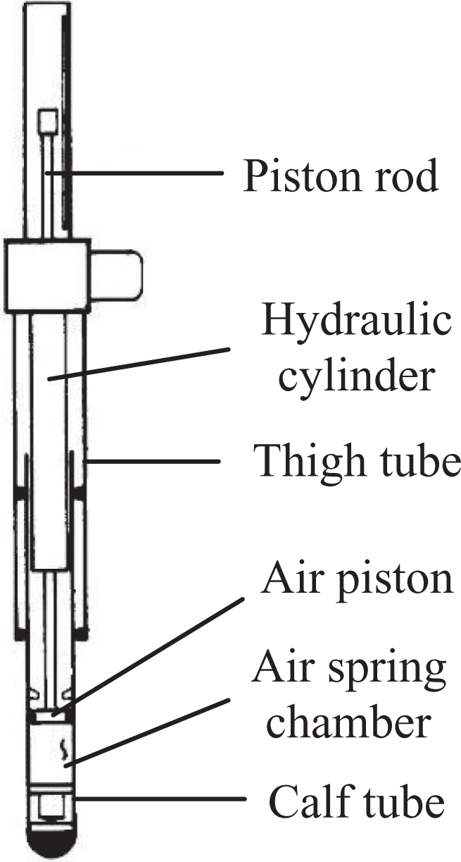
Hydraulic prismatic leg.
The prismatic leg is driven by a hydraulic actuator in series with an air spring. The hydraulic actuator has large output driving force, high adjustment precision, fast response speed, high precision control, and good anti-offset capability. The air spring provides shock absorption and reduces bottom impact and energy storage. When the passive impedance of the hydraulic actuator is adjusted by a series of air springs, the high-speed and high-thrust characteristics of the hydraulic pressure allow the leg to withstand a fast, powerful, and stable ground support phase, which is a good way to achieve flexibility and drive of the leg along the long axis and improve energy efficiency.
Inspired by the prismatic legs developed by Railbert et al., Ahmadi and Buehler designed a motor-ball screw-type prismatic leg, as shown in Figure 3. 8

Motorized screw-type prismatic leg.
The prismatic leg is driven by the linear motor-ball screw-spring mechanism for compliant drive. A quasi-static vertical oscillation between the weight and the leg spring can be supported by the periodic drive of the motor. Compared with the hydraulic prismatic legs designed by Railbert, this design uses an electric ball screw and a helical compression spring instead of a hydraulic actuator and air spring to better simulate the characteristics of the animal’s leg Achilles tendon.
The Scout II quadruped robot developed by Poulakakis et al. uses spring passively driven prismatic leg. Its leg design is shown in Figure 4. 9

Passive active prismatic leg.
The prismatic leg uses the spring’s own characteristics to achieve the telescopic movement of the mechanical leg. With no active drive actuators, the legs are lightweight and compact, with low inertia, and are rugged enough to withstand repeated impact loads and achieve fixed length and compliant operation.
Articulated legs
Compared with prismatic legs, the articulated leg uses a rotating joint instead of a linear prismatic joint to achieve leg length control. It has a similar function to the knee or elbow joint of the animal leg and has good biomimetic characteristics. Its topology is shown in Figure 5.
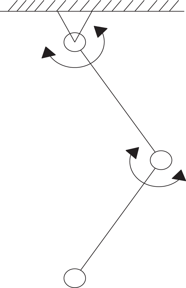
Articulated legs topology.
The articulated legs can be divided into mammal-type and sprawling-type articulated legs according to their leg configuration. 10 Here, the mammal-type refers to the fact that the leg is vertically positioned downward from the hip joint as a standard posture. The sprawling-type means that the first leg segment is placed in the horizontal direction, and the second leg segment is in the vertical direction as the standard posture. Table 2 shows the topologies and characteristics of the quadruped robots with different types of articulated legs. Comparing these two types of quadruped robots, mammal-type robots have faster walking speed, lower driving torque, and smaller footprint, while sprawling-type robots have higher stability, wider range of motion, and higher security.
Topologies and characteristics of quadruped robots with different types of articulated legs.

Mammal-type articulated legs
Boston Dynamics has done a lot of work on quadruped robot research and has achieved fruitful results. They developed the WildCat quadruped robot, the LS3 quadruped robot, the Spot quadruped robot, and the SpotMini quadruped robot using articulated legs. The specifications of these robots are not published yet; we can only get some information from the online videos published by Boston Dynamics.
The WildCat and the LS3 quadruped robots are powered by a two-stroke gasoline engine-hydraulic pump-electric servo cylinder. The two-stroke engine is used because its power density is higher than that of the four-stroke. Due to the slow response of the fuel engine and the large fluctuations in torque and speed, they are equipped with hydraulic energy storage tanks that provide instantaneous response power and reduce oil pressure fluctuations. Spot quadruped robot is driven by battery-motor-hydraulic pump-electric servo hydraulic cylinder. The replacement of the energy supply mode can effectively reduce the noise problem when the robot is running, and the motor has a fast response speed and a stable torque characteristic, and the configuration of the hydraulic energy storage tank can be cancelled. SpotMini quadruped robots are driven by battery-motor. The removal of the hydraulic pump and the electric servo hydraulic cylinder undoubtedly bring more flexibility to the structural design. The knee motor can be placed at the hip joint to drive the knee joint by traction mechanism. This leg design method can effectively reduce the inertia of the leg. The most obvious benefit is that the noise is greatly reduced. SpotMini is therefore known as the quietest robot developed by Boston Dynamics.
Semini et al. have developed the HyQ quadruped robot, 11,12 the improved HyQ2Max quadruped robot, 13,14 and the lightweight MiniHyQ quadruped robot 15 with articulated legs.
HyQ quadruped robot uses electro-hydraulic articulated legs. Its leg design is shown in Figure 6.

Electro-hydraulic-driven HyQ mechanical leg.
Combined with the high speed and high torque of the hydraulic system and the compact structure of the electric actuator, the drive system not only provides the high speed, high power-to-weight ratio, and robustness against torque peaks required for hip flexion/expansion joint and knee joint but also enables compactness of the hip abduction/adduction joint structure. The hip abduction/adduction joint consists of a tubular structure and a plurality of ball bearings that help to distribute the loads and achieve a firm connection between the leg and the body. The thigh is composed of parallel ribs that are connected to each other by links. The structure is not only light and sturdy but also provides sufficient space for hydraulic cylinder installation, while protecting the internal hydraulic lines and sensor cables. The shank is sleeve structure and adds a passive prismatic joint to offset or reduce the ground impact.
The HyQ2Max as an improved version has a wider range of motion and can be automatically aligned, with higher joint torque, faster movement speed, higher payload, higher robustness, and higher impact resistance, as shown in Figure 7.
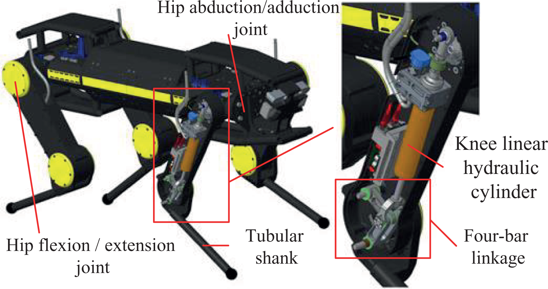
Hydraulically driven HyQ2Max quadruped robot.
The hip abduction/adduction joint of the mechanical leg adopts a double-blade rotary hydraulic actuator. It has dual torque characteristics but a small range of motion. The hip flexion/extension joint uses a single-blade rotary hydraulic actuator that produces less torque but a larger range of motion. Overall, the rotary hydraulic actuators output a constant torque independent of joint position, but with low torque-to-weight ratio. The knee joint is driven by a linear hydraulic actuator and four-bar linkage. The four-bar linkage is a good match for the asymmetrical torque characteristics of the knee joint, namely high torque during extension and low torque during retraction.
The MiniHyQ quadruped robot achieves a wider range of leg joint movement while achieving weight reduction in the legs. Its leg design is shown in Figure 8.

Hydraulically driven MiniHyQ mechanical leg.
The hip joints are driven by linear hydraulic actuators and rotary hydraulic actuators for a wider range of joint motion. The electric pump is powered by the vehicle battery, and the hydraulic pipeline is arranged in the machine body, and the branch pipeline is not arranged on the mechanical leg, so as to ensure the leg is light as much as possible. To obtain a larger range of motion for the knee joint, an isogram mechanism based on the crossed four-bar linkage mechanism is designed, which has a variable instantaneous center of rotation and which can provide torque requirements at different stages of the knee joint, and the range of joint motion can reach 180°.
Hutter et al. developed the StarETH 16 and the ANYmal quadruped robot 17,18 with articulated legs.
A series elastic actuator (SEA)-driven articulated leg ScarlETH is used by the StarETH quadruped robot, as shown in Figure 9. 19,20

SEA-driven ScarlETH mechanical leg. SEA: series elastic actuator.
The mechanical leg is driven by SEA composed of a micro-drive chain/cable pulley and a linear compression spring, which can realize the compliant output of the joint and the upward movement of the joint motor, reducing the hardware performance requirements for the controller, the actuator, and the transmission. Benefiting from the nonlinear spring-damping characteristics, it exhibits minimal damping and linear, no-lag torque/deflection ratio during stance phase, while having maximum hysteresis damping due to spring damper pre-compression during flight phase. This satisfies the need for high damping and no oscillation during flight phase and low damping and efficient energy storage during stance phase. The thigh is made up of hollowed-out thin-walled parallel ribs. The structure is not only light and sturdy but also provides sufficient space for the drive chain mechanism to be installed and protected. The shank is a cylindrical tube, and the elastic elements of the knee joint are arranged inside.
The ANYmal quadruped robot’s leg uses a highly integrated SEAs to drive the joints. The actuator consists of a high-torque motor, a harmonic drive gearbox, and a rotational spring. The joint units are integrated with drive electronics, sensors, and joint axle bearings, so the mechanical legs do not require any additional bearings, proprioceptive sensors, transmissions, or electronic components. The knee joint actuator is placed adjacent to the joint for direct drive, avoiding the need to design additional transmission mechanism. The joints are arranged in an offset manner so that all joints can be fully rotated, enabling a wide range of motion, which is essential for high mobility. The leg structural parts are made of carbon fiber to compensate for the influence of the adjacent arrangement of the joint motor on the weight of the leg, as shown in Figure 10.

SEA-driven ANYmal quadruped robot. SEA: series elastic actuator.
Wensing et al. recently developed the Cheetah3 quadruped robot with articulated legs, which has a larger range of motion than the predecessor Cheetah2, as shown in Figure 11. 21

PA-driven Cheetah3 robot. PA: proprioceptive actuator.
The three joints of the mechanical leg are driven by the self-made high torque density proprioceptive actuators (PAs). 22 The actuator coaxially integrates two motors and the planetary gear train. It has appropriate torque output, high torque density, low weight, high backdrivability, high transparency, and high efficiency and enables force control in applications with highly dynamic environmental interactions. The abduction/adduction joint of the hip joint is driven by the actuator and a linkage mechanism, which enables the robot to realize the swinging and twisting motion. The knee joint is driven by the actuator and a drive chain mechanism. The knee joint design method can make the knee joint rotation angle greater than 180°, thereby the knee joint can be turned over.
Kenneally et al. designed a direct-drive quadruped robot Minitaur, as shown in Figure 12. 23

Direct-drive Minitaur quadruped robot.
The robot’s innovation is that the mechanical leg is driven by the direct drive of the motor, giving up the use of gears, belts, chains, or other transmission mechanisms to amplify the effective torque generated by the motor. This leg design can achieve high mechanical strength, high power, high efficiency, and high bandwidth control, but facing high heat. So the leg can only be operated away from the peak of power and efficiency. This mechanical leg has two active degrees of freedom, connected by a five-bar linkage, and has a strong terrain adaptability.
China’s Laikago, Jueying, and Chituare are motor-driven quadruped robots with articulated legs, as shown in Figure 13.
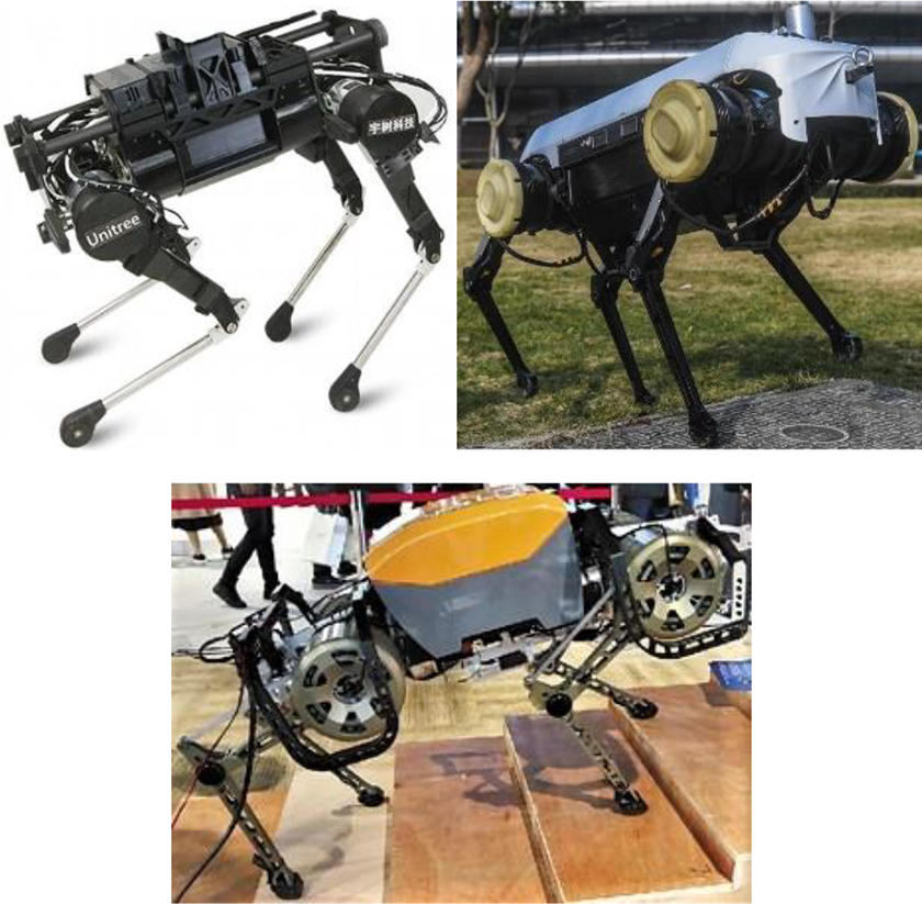
Laikago, Jueying, and Chituare quadruped robots.
They use a similar leg configuration, joint motor arrangement, and knee joint transmission. By arranging the knee joint motor at the hip joint and using a link mechanism as a traction mechanism, the robots can effectively reduce the leg inertia during movement for better motion performance.
Li Yubin et al. developed SCalf quadruped robot with articulated legs. Its leg design is shown in Figure 14. 24,25

Hydraulically driven SCalf mechanical leg.
Three active drive joints are driven by servo hydraulic actuators of the same parameters. Passive prismatic joint is designed on the shank, and utilizing the compressibility of the spring can effectively cushion the impact loads and vibration for achieving passive compliance of the leg. The linkage structure at the hip and thigh is integrally processed with superhard aluminum alloy to ensure the structural strength while minimizing the weight of the mechanism.
Shi et al. designed an articulated leg with flexible joints, as shown in Figure 15. 26

Mechanical leg with flexible joint.
The flexible joint of the mechanical leg is mainly composed of a servo motor, a timing belt mechanism, a harmonic drive gearbox, and a flexible output mechanism, which are arranged in parallel. The flexible output mechanism mainly includes a spring mount, four sets of compression springs, and an output disc. When the gearbox output drives the spring mount to rotate, the side of the symmetrically arranged spring is compressed while the other side is elongated. Using the restoring force of the spring drives the output mount to rotate to achieve flexible output. The timing belt design between the motor and gearbox can effectively avoid the problem that the direct connection of the motor and the gearbox leads to a long drive mechanism. The upward movement of the motor reduces the inertia and consequently improves the performance of the mechanical leg. The hip joint and the knee joint adopt the same flexible joint and are directly connected by the aluminum alloy structural parts, which embodies the high integration of the mechanical leg. The prismatic joint design at the shank can realize the passive compliance of the mechanical leg.
Wang Binrui et al. designed a quadruped robot driven by pneumatic muscles, as shown in Figure 16. 27

Pneumatic muscles–driven quadruped robot.
The mechanical leg is constructed by two antagonistic pneumatic muscle joints in series, which has two degrees of freedom. Pneumatic muscles have the characteristics of bionic muscle characteristics, inherent flexibility, high power-to-weight ratio, low noise, and so on, but due to the compressibility and hysteresis characteristics of the gas, the control accuracy of pneumatic muscle drive is not high. The mechanical leg does not have a design of the hip abduction/adduction joint, and the leg structure design is relatively simple without adopting complicated structural design method, which is related to the purpose of studying the control precision of the actuator.
Gao Jianshe et al. designed a serial-parallel articulated leg, as shown in Figure 17. 28

Serial-parallel articulated leg.
The mechanical leg is composed by a hip, a thigh, and a shank via sequential connection. The hip joint is a three degrees of rotational freedom (3-RRR) parallel mechanism. The three hip motors mounted on the fixed platform utilize a transmission mechanism to drive the movement of the moving platform to achieve three rotational degrees of freedom. The fixed platform is fixed to the body. On the one hand, the design of the hip joint improves the carrying capacity of the mechanical leg, on the other hand, the inertia of the leg is reduced, and the movement performance of the mechanical leg is improved. The knee joint is driven by a linear hydraulic actuator that provides sufficient driving torque and improves the carrying capacity of the knee joint. The prismatic joint design at the shank can achieve passive compliance of the leg.
Sprawling-type articulated legs
The researchers at Tokyo Institute of Technology have done a lot of work on sprawling-type articulated legs and developed the TITAN series of quadruped robots using this type of leg. TITAN-XIII quadruped robot is the result of their recent research.
The TITAN-XIII quadruped robot features a lightweight and compact mechanical leg for high speed, energy savings, with high stability, wide range of motion, and ease of maintenance, as shown in Figure 18. 10,29
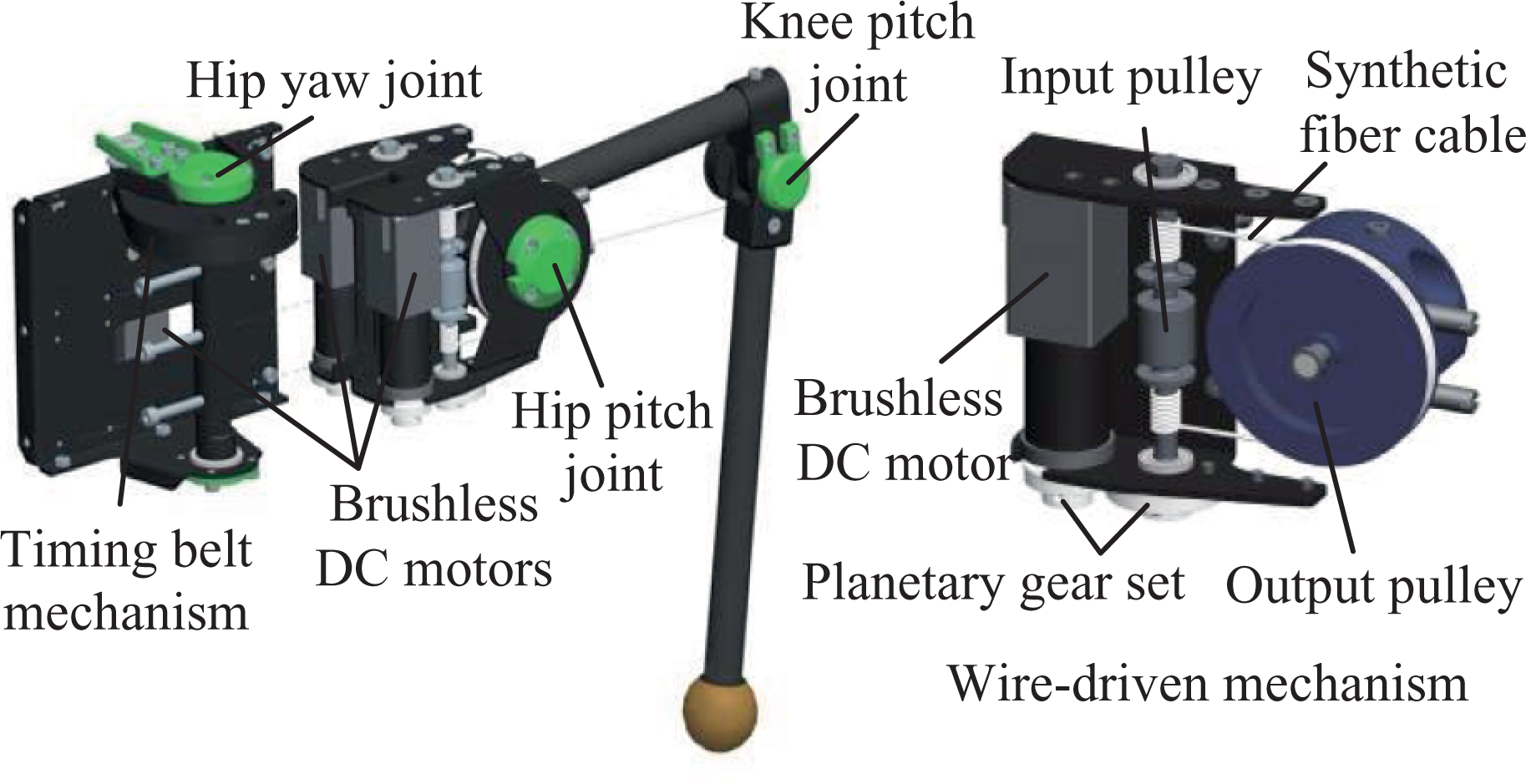
Sprawling-type articulated leg of TITAN-XIII.
The biggest feature of the mechanical leg is the introduction of a wire-driven mechanism that includes a brushless direct current (DC) motor, a planetary gear set, two synthetic fiber cables, and input and output pulleys. At the same time, a coaxial tensioner shaft is installed as the input pulley to the wire-driven mechanism to compensate for its expansion. Using the wire-driven mechanism to transmit power to each axis, the motors can be located at the base of the leg, consequently reducing its inertia. Additionally, the drive mechanism can be modularized for easy disassembly and improves the maintainability of the leg. A timing belt mechanism is introduced as transmission and reduction mechanism to drive the hip yaw joint, which is composed of small timing pulley, big pulley, and timing belt. The links connecting each joints are made of the carbon fiber reinforced polymer/plastic (CFRP) pipe which is very light and has high strength, consequently reducing the weight of the leg. The connection of the two links at the knee joint is offset, which can avoid the collision of two links and realize parallel folding. The introduction of this connection method can expand the range of motion and increase the strength of fixing the CFRP pipe.
Redundant articulated legs
The redundant articulated legs is the extension of the articulated legs with at least one more rotating joint. This type of legs are similar to the toed or hoof animal’s legs observed in nature and has better biomimetic and kinematic properties in geometric topography. More common type of the redundant articulated legs found in the literature has three rotating joints. Its topology is shown in Figure 19.

Redundant articulated legs topology.
Garcia et al. developed a redundant articulated mechanical leg hybrid actuator development (HADE) simulating the horse leg structure, as shown in Figure 20. 30,31

SEA-driven HADE mechanical leg. SEA: series elastic actuator.
The mechanical leg consists of thigh, shank, and foot, connected by hip, knee, and ankle joints. The design of each link structure can achieve a large payload-to-weight ratio and provide impact tolerance. The toe has a rubber pad that provides shock absorption when in contact with the ground and also increases the friction between the ground and the foot, improving horizontal propulsion. The actuator consisted of a brushless DC motor, a ball screw, and a die-compression spring, which can achieve backdrivability and have the ability to withstand shock and vibration and provide good force control at the joint. These characteristics are largely beneficial to the adaptability to the ground in high-speed motion. To achieve a more natural movement and improve leg-to-ground interaction, a magneto-rheological (MR) rotary brake is integrated at the knee joint. The MR brake consists of an outer housing, the MR fluid and a rotor jointed to the knee joint axis, and utilizing the rheological property of the fluid to produce different rotor braking torques can provide controlled viscous rotational damping.
Based on the HADE, Garcia et al. developed the improved HADE2 redundant articulated leg, as shown in Figure 21. 32

SEA- and SDF-driven HADE2 mechanical leg. SEA: series elastic actuator; SDF: surface digital flexor.
The mechanical leg achieves better leg mass distribution, better elastic energy recovery, and higher speed than HADE. SEAs are still used to drive the hip and knee joints of the mechanical leg. The ankle joint actuator is replaced by a spring similar to the surface digital flexor. The mechanical structure of the thigh and shank has been extensively modified by an optimization algorithm to achieve a large payload-to-weight ratio.
Kim et al. designed a redundant articulated leg based on the leg structure of cheetah, as shown in Figure 22. 33,34

PA-driven Cheetah1 and Cheetah2 mechanical leg. PA: proprioceptive actuator.
The mechanical leg is driven by a self-made PA that provides a unique combination of high torque density, high-bandwidth force control, and ability to mitigate impacts through backdrivability. The knee motor is integrated into the hip and the knee joint is driven by a parallel linkage mechanism. This method can significantly reduce leg inertia without affecting leg strength. The ankle joint is passively driven by a parallel linkage mechanism, which mimics the traction mechanism of the Achilles tendon. The entire drive system design is compact and sturdy. The mechanical leg is made of fiber composite material, and the hollow tube is filled with foam, which simulates the bone structure to create a lightweight and high-strength bionic leg structure.
Ijspeert et al. developed the Cheetah-cub series of quadruped robots with redundant articulated legs, as shown in Figure 23. Its mechanical leg design is inspired by cat legs. 35,36
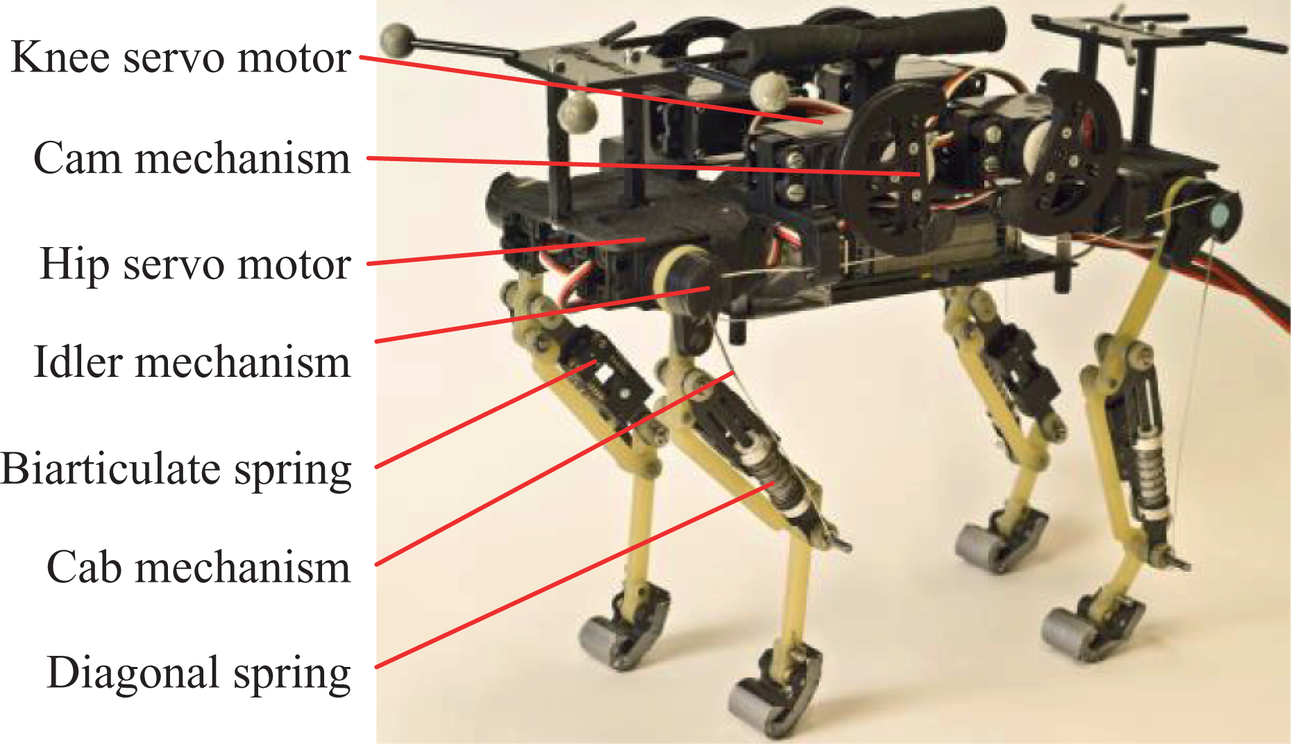
RC-driven (servo motor) Cheetah-cup quadruped robot.
The leg configuration based on a spring-loaded pantograph mechanism that provides very good leg compliance and very low leg stiffness. The mechanical leg drive motors are all arranged inside the body to minimize the inertia of the leg. The knee actuator is mounted at the body’s center. The knee joint is driven by a cable mechanism and an antagonistic diagonal spring. The cable mechanism comes from the knee motor cam and is connected to the lower end of the diagonal spring through the idler pulley at the hip joint. The low radius idler is designed to separate the knee and hip motor movements. This allows the hip and knee actuators to be installed proximally. Hip actuator is directly installed between leg and body to drive the hip joint movement. A biarticulate spring element is used to passively drive the ankle joint, which can cushion the instantaneous impacts of the ankle joint when touching the ground, and realize the passive compliance of the leg, so that the robot’s self-stability and maximum speed are improved.
Boston Dynamics developed the BigDog quadruped robot with redundant articulated legs, as shown in Figure 24. It is known as the world’s most advanced robot for adapting to rugged terrain. 37,38

Hydraulically driven BigDog quadruped robot.
The mechanical leg contains four active joints that are driven by hydraulic actuators. A water-cooled two-stroke internal combustion engine provides energy to drive the hydraulic pump to deliver high-pressure hydraulic oil to the leg hydraulic actuators through filters, manifolds, accumulators, and other piping systems to drive joints movement. The hydraulic servo system has the advantages of large power-to-weight ratio, high energy density, and high control precision. The structure of the thigh and shank consists of two parallel ribs. This design method not only overcomes the lateral loads of the coronal and cross sections but also provides sufficient space for actuator and hydraulic piping arrangements. A passive prismatic joint is added to the foot to counteract or attenuate the foot impact during walking, thereby achieving passive compliance of the leg.
Li Mantian et al. designed a hydraulically driven mechanical leg, as shown in Figure 25. 39

Hydraulically driven Harbin Institute of Technology mechanical leg.
The mechanical leg uses a double-acting hydraulic actuator with a large power-to-weight ratio to reduce the weight of the leg and the moment of inertia and reduce the influence of the leg swing on the posture of the body. The crank rocker mechanism is designed to drive joints rotation. By configuring the relative position between the joint and the connecting joint of the hydraulic cylinder, the force arm of the hydraulic cylinder relative to the joint can be optimized to ensure that the flow rate of the hydraulic servo valve and the output force of the hydraulic cylinder are within a reasonable range under extreme conditions. The hip abduction/adduction connection frame adopts the hollow truss-like structure and the thigh and the shank adopt reinforced ribs structure, which ensures the strength and rigidity of the structural parts while reducing the self-weight. The prismatic leg design at foot can achieve the passive compliance of the leg.
Ma Zongli et al. designed a quadruped robot based on the bone–muscle biomechanical properties of the dog’s fore leg, as shown in Figure 26. 40
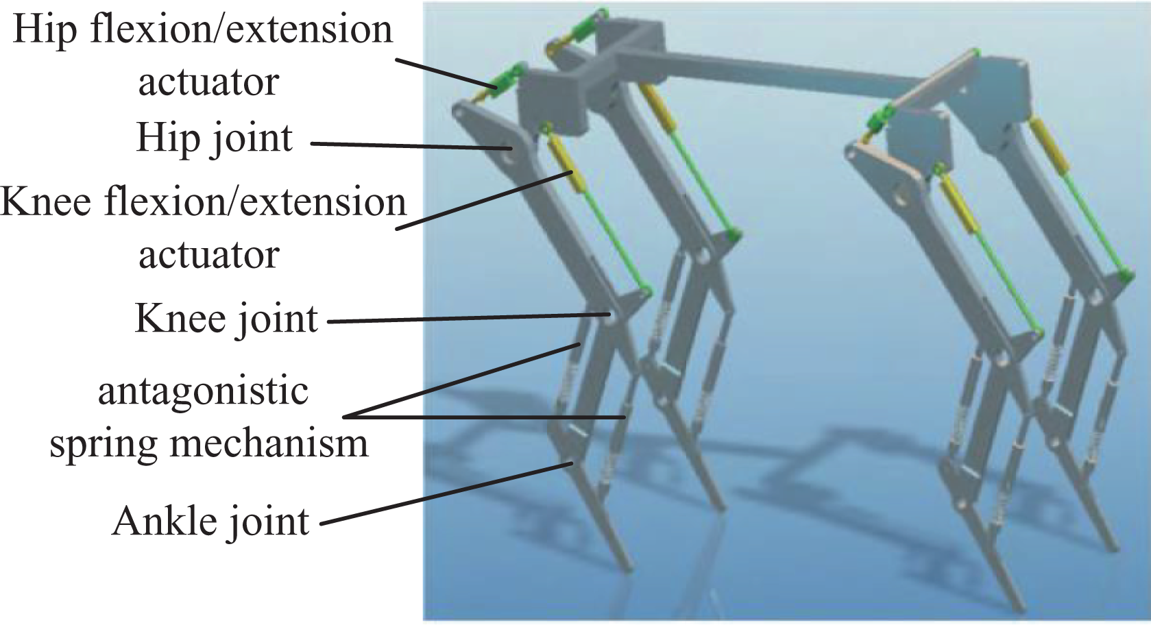
Hybrid-driven quadruped robot.
The innovation in this mechanical leg design is that the mechanical leg ankle joint is passively driven by a pair of antagonistic spring mechanism. The spring mechanism replaces the hydraulic actuator to simplify the hydraulic drive system of the leg, making the leg structure simpler and lighter, consequently reducing the inertia of the leg. In addition, it can greatly increase the compliance of the leg and achieve efficient absorption of impact energy.
Comparative analysis of three types of legs
Through the above example analyses, we can get the following conclusions. The prismatic legs simplify the controller, and the choice of telescopic actuators is diverse, such as pneumatic actuators, hydraulic actuators, and motor screws. The leg structure is the simplest and lightest, with the lowest inertia. However, this type of leg limits its own kinematic performance due to fewer rotating joints, which results in insufficient terrain adaptability. At present, this type of leg is used more in the other two types of legs as a passive compliant joint. The redundant articulated legs are similar to the toe or hoof legs observed in nature. It has better bionics in geometric topology, better motion performance, greater self-stabilization speed domain, wider leg-foot motion space, and higher energy efficiency. It shows greater advantages in complex terrain adaptation and obstacle crossing. However, the introduction of more rotating joints comes at the cost of introducing additional actuators, which not only increases the complexity of the controller but also places higher demands on sensing and leg structure design. How to solve the inertia of the distal leg is a problem that must be considered. The articulated legs are located between the prismatic legs and the redundant articulated legs in terms of motion performance, structural complexity, and ease of control and have the best balance between complexity and performance, thereby this type of leg is currently used more on quadruped robots.
Research of quadruped robot’s mechanical leg
The mechanical leg is a multi-body structure composed of the actuator and the bearing structural parts. Its motion performance and carrying capacity are largely affected by these two aspects. Therefore, in the study of mechanical legs, research on actuators and bearing structural parts are indispensable.
Actuators research
Mechanical leg motion involves repeated dynamic events such as impact, rapid leg swing, and high force interaction with uncertain terrain. Designing actuator systems for high dynamic legged robots has always been one of the major challenges in robotics research. The ideal actuator is to maximize torque, bandwidth, and power while minimizing friction, inertia, and mass loss. 41 However, due to the multifactor coupling relationship between them, it is not clear how to design an actuator to meet these contradictory requirements.
Conventional electromagnetic actuators are often combined with gearbox to utilize high gear ratio to ensure maximum positional accuracy and stiffness. However, increasing the gear ratio will amplify the impact loads and increase the overall mechanical impedance of the system, while reducing the high gear ratio will increase friction losses and reduce the overall mechanical strength of the system. When the mechanical leg interacts quickly with the environment or there is an impact, a very high impact load is generated at the end actuator and the force control capability is limited. Conventional actuators with high gear ratio do not reduce the effects of the high mechanical impedance of the actuator system resulting from the high impact load. In order for a quadruped robot to dynamically interact with the ground and walk steadily in an unstructured environment, minimizing mechanical impedance is critical. To solve this problem, two new paradigms of actuator design have been proposed, namely the SEA and the PA.
SEAs minimize mechanical impedance by connecting the spring element in series with a high impedance actuator. 42 The addition of the elastic element can lower the filter vibration load, greatly reduce the peak value of the gear force, convert the force control problem into a position control problem or make the stable force control easier to implement, and provide the possibility of energy storage. Hurst et al. adjust the SEA stiffness by using a cable and pulley to pretension the spring. 43 Kim et al. designed a hybrid variable stiffness actuator that adjusts the stiffness of the system by adjusting the torque arm mechanism. 44 Kong et al. designed a compact rotating SEA using a combination of a turbine, spur gear train, and a torsion spring. 45 Vamshikrishna et al. utilize a leaf spring in combination with different positions of the two movable support parts to achieve variable stiffness adjustment. 46
Proprioceptive actuation is a method proposed by Wensing et al. to reduce high-impact forces by introducing completely different actuator structures. 21 The actuator does not use springs, stiffness adjustment mechanisms, and force/torque sensors to eliminate high inertia from the end of the actuator, but by minimizing mechanical inertia and gear ratio to make the system light when subjected to impact, thereby protecting the system from high-impact forces. To compensate for the low-output torque due to reduced gear ratio, the actuator uses a large radius stator and rotor to meet torque density requirements. Compared to the SEA, the actuator can achieve high bandwidth force control without contact force feedback.
The hydraulic actuator is another type of actuator that has higher output power, higher power density, higher bandwidth, faster response, and stronger anti-interference ability compared with electromagnetic actuators. 47 Quadruped robots with high load requirements are often driven by such actuators. Hydraulic cylinders are a form of hydraulic actuators that are available in both linear and rotary versions. 48 Rotary hydraulic cylinders are relatively complex and of high quality and are usually placed on the hip of the mechanical legs. For example, the mechanical legs of the HyQ2Max and MiniHyQ quadruped robots use this layout design. The linear hydraulic cylinder has the characteristics of simple structure, lightweight, and stable performance and is suitable for long-distance transmission, which can effectively improve the leg mass, reduce the inertia of the leg, and make the mechanical leg run more stable and easy to control. This type of actuators is most common on quadruped robots with hydraulic actuators, such as BigDog, WildCat, and HyQ quadruped robots.
Structure design
Due to the rapid discrete ground contact, the mechanical legs are subject to high ground reaction forces, resulting in high stress and stress concentrations throughout the leg structure resulting in failure. At the same time, the mechanical leg should have at least three degrees of freedom to handle the ground reaction forces in the three-dimensional environment, which increases the complexity of the leg structure. Due to the existence of this complexity and high ground reaction forces, the design of mechanical leg structures is challenged.
When designing the mechanical leg structure, the relationship between agility and overall structural quality should be weighed. For example, simply increasing the thickness of the structure may solve the high stress problem of the mechanical leg, but high quality will cause high inertia and high inertia will limit the rapid swing of the leg, thus limiting the agility of the leg. Increasing the power of the actuator will increase the agility of the mechanical leg to a certain extent, but a significantly increased actuator weight will increase the overall weight and inertia of the mechanical leg, which in turn will affect the agility of the mechanical leg. Reducing the inertia of the legs is considered an inevitable choice to solve the problem. To reduce the inertia of the legs, the total mass of the structure must be reduced and the leg mass should be reasonably distributed under the premise of ensuring the structural strength. Methods commonly used to reduce leg mass and inertia are structural topology optimization, structural bionics, transmission mechanism optimization design, and the use of high specific stiffness and specific strength materials.
The traditional structural topology optimization is usually assembled by discrete structures, that is, the reinforcing ribs are adopted on the sagittal plane where the mechanical leg is most stressed, and the reinforcing rib distribution is determined according to the loaded condition. The two reinforcing ribs are often arranged in parallel to overcome the lateral load of the tubular surface and the cross section, and the middle can be used to arrange the actuator and drive and control lines. For example, the United States BigDog, AlphaDog, Italy MiniHyQ, Switzerland StarlETH, and other robots use this design method. However, since the leg is subjected to a composite load consisting of stretching, compression, bending, shearing, and torsion, in order to ensure sufficient structural strength, the reinforcing ribs have to increase the structural size and the solid connection structure needs to be added between the two parallel ribs, thereby increasing the leg mass and mass distribution which in turn affects the agility of the movement. To solve this problem, structural bionics can be a good alternative.
By studying the adaption of animal bone to multiaxial stress distribution and anisotropic mechanical properties of large impact loads, and the special cross section and shape of the bone, as well as nonuniform equal-strength optimal distribution of high-density and high-strength materials, the goal of structural bionics is to build mechanical legs that resemble animal leg structures and achieve similar animal leg functions. The structure bionics can realize the light weight of the structure and the optimization of the material distribution, and at the same time, the specific strength and the specific stiffness can be greatly improved, and the modality of the structure is also improved in terms of dynamics. 49 For example, by imitating bone structure, the MIT Biomimetic Robotics Lab uses fiber composite materials and fills the foam with an empty tube to create a lightweight, high-strength bionic leg. 50
The layout of the transmission mechanism generally has three forms. The first type is a tandem mechanism that is widely used for mechanical legs, the actuator of which is usually arranged near the joint to be driven. When handling high load, high speed, and high mobility, the power required for leg braking and propulsion is large, which results in the actuator with a larger structural size and quality. Therefore, this layout will bring a larger leg mass and consequently increase the inertia of the leg. The second type is a parallel mechanism or a linkage mechanism, which has a large rigidity and can increase the payload-to-weight ratio of the mechanical leg. However, this layout is limited by working space of mechanism itself, making it difficult to cross obstacles at high speed.
51
Some researchers have proposed combining the parallel mechanism and the tandem mechanism to form the hybrid mechanism. Compared with the tandem mechanism, this layout has lower requirements on driving torque and less energy loss, but the space occupied is still large. The third type is tensegrity mechanism. This method not only helps to improve the arrangement of the drive, reduce leg inertia, and achieve a compact design but is also closest to animal prototypes. In addition, the method has the following potential advantages. It can achieve multi-actuators coupled output power in timing, reducing system power consumption. Elastic element can be added to adjust stiffness, which facilitates shock absorption and energy cycling. The bending stress can be changed to the tensile stress, thereby improving the stress characteristics of the actuator and the structural parts and achieving weight reduction. New lightweight telescopic drive materials such as carbon nanotube actuating material
52
and piezoelectric material can be used.
It can be seen that the mechanism design with the tensegrity feature is an important way for the mechanical legs to achieve high strength and light weight. For example, Switzerland Ijspeert and Japan TITAN-XIII quadruped robots simply use the tensegrity mechanism.
Some suggestions on the development of the quadruped robot’s legs in the future
After decades of development, the mechanical legs have made great progress, but there is still a big gap compared with animal legs. The animal legs use the bone as a lever and the joint as a hub, driven by muscle contraction. The equal strength distribution of the leg bones, structural anisotropy, and the pore tube structure give it the lightest structural weight under specific load conditions. The power density of the muscle (0.3 kW/kg) is much smaller than the power density of electromagnetic actuator (5.68 kW/kg) and the hydraulic actuator (5.7 kW/kg).
53
However, it can achieve better driving performance than electromagnetic and hydraulic actuators and support the body to achieve high-speed maneuvering capability such as running and jumping. This is inseparable from the special tensegrity structure of the muscle-skeleton. Faced with complex terrain and multi-tasking requirements, the wheel-leg hybrid drive system allows quadruped robots to have better terrain adaptability and motion diversity. Therefore, from the perspective of structural bionics, functional bionics, and wheel-leg hybrid drive, several suggestions for the development of the quadruped robot’s legs in the future are proposed. (1) Research on bionic topology optimization theory
As the animal’s legs move, it will withstand a composite load consisting of stretching, compression, bending, shearing, and torsion. This composite load forms a multiaxial random stress distribution composed of tensile stress, compressive stress, and shear stress in the bone and will withstand an impact load of 2.5 to 3 times its own weight during fast running. The mechanical leg carrying state is essentially the same as the animal’s leg, and the leg structural members will withstand large complex bending moments. At present, the conventional topology optimization method is difficult to meet the high strength and lightweight design and application requirements of mechanical legs under large impact and multi-axial composite loads. Therefore, the research on bionic topology optimization theory, using the finite element analysis methods of bone growth and remodeling to achieve the goal of lightweight leg structure, material distribution optimization, high specific strength, and high specific stiffness will be a new way to design the mechanical leg structure in the future.
(2) Research on the tensegrity theory
Multi-muscle traction and chronological actions of animal legs dynamically change the number of driving forces and provide time-varying optimal power output. The strength and elasticity of the mechanism are adjusted by dynamically adjusting the muscle tension of the legs to adapt to the impact of uneven ground. The tensegrity system optimizes structural dimensions, mechanical strength, mass distribution, and energy consumption of the legs from the overall perspective. At present, the application of lightweight tensegrity mechanism on robots in the world is gradually becoming a hotspot. In addition to simply using a single-drive tensegrity mechanism on the mechanical leg, the problem of how to configure multiple actuators, optimize structural stiffness and force, reasonable configuration, and mechanism adjustment strategy has not yet discussed in depth. The research on the tensegrity theory mainly includes multi-actuators tensegrity mechanism power configuration and compact and lightweight tensegrity mechanism structural parts design methods.
(3) Research on wheel-leg hybrid drive system
On flat terrain, the wheeled system has the advantages of high speed, outstanding performance in terms of payload-to-weight ratio, stable operation, and easy control. While legged system can perform tasks in rugged terrain. The wheel-leg hybrid drive system combines the characteristics of the wheel and leg system to design a quadruped robot’s leg, which combines the advantages of both forms of motion, that is, walking is used in rough-terrain and rolling is used in flat terrain. This design method improves the running efficiency of the quadruped robot. The application of the wheel-leg hybrid drive system is rarely found in quadruped robots. The robot handle developed by Boston Dynamics uses the wheel-leg hybrid drive system. By combining the rough-terrain capability of legs with the efficiency of wheels, Handle has the best of both worlds.
Conclusion
This article classifies the quadruped robot’s legs according to degrees of freedom and introduces and analyzes a lot of typical examples of each type of mechanical legs from the perspective of drive design and structural design. By comparing and analyzing these three types of mechanical legs, it is concluded that the articulated legs are the best mechanical leg form of the three types. A large number of case studies help to gain a deeper cognition and understanding of these three types of mechanical legs and then provide a reference and basis for selecting and designing which type of mechanical leg form and how to design. Based on the previous analysis, the design methods of the mechanical leg are comprehensively summarized and studied from the two aspects of actuator design and structural design. It helps to understand and recognize these design methods of the mechanical leg as a whole and provides theoretical guidance for the design of the mechanical legs. Finally, from the perspective of structural bionics, functional bionics, and wheel-leg hybrid drive, some suggestions for the development of the quadruped robot’s legs are proposed. It can specify a direction for the future development of quadruped robot’s legs.
Footnotes
Declaration of conflicting interests
The author(s) declared no potential conflicts of interest with respect to the research, authorship, and/or publication of this article.
Funding
The author(s) disclosed receipt of the following financial support for the research, authorship, and/or publication of this article: This project is sponsored by National Natural Science Foundation of China (NSFC) under grant 51475373.