
Abstract
NAO is the first robot created by SoftBank Robotics. Famous around the world, NAO is a tremendous programming tool and he has especially become a standard in education and research. Aiming at the large error and poor stability of the humanoid robot NAO manipulator during trajectory tracking, a novel framework based on fuzzy controller reinforcement learning trajectory planning strategy is proposed. Firstly, the Takagi–Sugeno fuzzy model based on the dynamic equation of the NAO right arm is established. Secondly, the design and the gain solution of the state feedback controller based on the parallel feedback compensation strategy are studied. Finally, the ideal trajectory of the motion is planned by reinforcement learning algorithm so that the end of the manipulator can track the desired trajectory and realize the valid obstacle avoidance. Simulation and experiment shows that the end of the manipulator based on this scheme has good controllability and stability and can meet the accuracy requirements of trajectory tracking accuracy, which verifies the effectiveness of the proposed framework.
Introduction
In recent years, humanoid robots have attracted the attention of many researchers. Humanoid robot can imitate certain physiological perception, behavioral characteristics, social communication ability, and even some of thinking ability of human beings and has a higher intelligence. 1 Humanoid manipulator as the most common and the most important actuator in the humanoid robot can not only cooperate with other actuators to complete a series of activities such as crawling, handling, and throwing, it can also be used to perform specific tasks in a complex environment. 2 –4 It is one of the basic tasks of robot control that the end effector of the manipulator moves according to a desired trajectory. However, with the development of the production demand and the change of the service object, the requirements for the motion control of the manipulator are also increasing. How to control the end of the manipulator to achieve good motion planning and tracking has become a research hotspot in the field of humanoid robot control in recent years. 5
The purpose of the trajectory tracking of the manipulator is to allow the position and speed of the robot track a desired trajectory by giving the driving torque of each joint. 6,7
When the accuracy requirements of trajectory tracking are not high, the influence of dynamics on the movement may not be considered. So, the manipulator usually uses the model-free proportion–integral–derivative (PID) control. However, with the increasing of automation, the tasks completed by the manipulator become more and more complicated, and the performance and the control precision of the manipulator have changed. Especially in the case of high precision and real time, the traditional control effects can’t meet performance requirements. 8 For the problem of motion control of manipulators, scholars have done a lot of research work. Ranjan et al. 9 studied hand–eye coordination system of NAO robot. This article studied the identification of the kinematics model of the manipulator and the calculation using the monocular visual Bouquets calibration method. The kinematic model of the left manipulator is established using Denavit–Hartenberg (D-H), and then the adaptive neural network fuzzy system is applied to the kinematic inverse solution calculation. Finally, the experimental analysis verified the error of the hand–eye coordination system was effectively reduced. Vázquez et al. 10 proposed a continuous-time neural network control scheme, which was successfully applied to the trajectory tracking control of a 2-degrees-of-freedom (DOF) direct-drive manipulator. The article used the recurrent high-order neural network (RHONN) structure to dynamically identify the controlled object online and then use the backstepping method to construct the local neural network controller of the RHONN subsystem. Experiments showed that the system can effectively counteract the effects caused by the coupling of friction and gravity between the subsystems and improve the tracking effect of the end effector. Nugroho et al. 11 discussed the problem of motion planning using two arms of NAO for games. This article established a positive kinematics model based on the improved D-H movement analysis method and obtain kinematic inverse solution using an inverse transformation method. Based on this kinematics model, nine pose interpolation points were generated using the trajectory planning method of 3-D Cartesian space. The deviation compensation experience value manually settled overcome the positional deviation of the end effector by many experiments, and finally, smooth movement of the manipulator was realized. Yuan and coworkers 12 developed a D-H kinematics model of the manipulator and visual servo control module by combining monocular vision of NAO with Kinect stereo vision. Position-based visual servo (PBVS) control method was designed, and the iterative learning algorithm was used to improve the PBVS control law and complete the task of delivering the household goods. The proposed algorithm is mainly aimed at the situation that the objects are simple in the experimental environment and the features of the target objects are extracted easily. Ren 13 used the particle swarm optimization (PSO) algorithm to optimize the redundant parameters in the trajectory and built a “knowledge” database in the work environment, which enabled the manipulator to achieve rapid and continuous response to the high-speed target under the condition of satisfying global constraints. Because the reactive optimization of fast action is not analyzed using dynamics, it may cause the certain imbalance of the robot. However, it still has important guiding significance for improving the reaction speed of the manipulator.
From the view of work task, the control problem of the manipulator is a process from simple location operation to trajectory tracking and intelligent learning. From the view of control technology, it is a process from simple logic control to high-precision PID adjustment, then to dynamic intelligent control. Now, the research on the control algorithm of the manipulator has made good progress, but some algorithms have limitations, such as ignoring external disturbances or adding a high-performance computer. Therefore, the accuracy of the motion control of the manipulator still needs further study.
The manipulator of this article is the arm of humanoid robot NAO for the object of motion control. This manipulator has the advantages of compact structure and flexible movement. 14 From the view of the control, the manipulator is a complex nonlinear system with multiple inputs and multiple outputs. The study of the manipulator based on dynamics is a necessary basis for achieving high-precision operations. 15 And the Takagi–Sugeno (T-S) fuzzy control technology has a high degree of nonlinear approximation mapping capability and robustness and is suitable for solving the analyzed and control problems of complex nonlinear uncertain systems than other models. 16 –18 By building a fuzzy model and a controller, high-precision tracking of the robot arm can be achieved.
The rest of this article is organized as follows. It describes the design of Q-learning method based on the T-S fuzzy parallel distributed compensation (PDC) control structure in the second section. In the third section, the trajectory tracking of a desired curve for a fuzzy model-based (FMB) manipulator closed-loop system is described. The obstacle avoidance and grasping experiment are designed using Q-learning algorithm in the fourth section. Finally, conclusion and future work are discussed in the fifth section.
Algorithm design
This article includes trajectory tracking and trajectory planning. PDC control based on T-S fuzzy is used to control the position of the trajectory tracking, and the RL algorithm is used for trajectory planning of obstacle avoidance.
Dynamic model
The humanoid robot NAO has five DOFs for each arm. 19 For example, there are two DOFs with the RShoulderRoll and the RShoulderPitch on the shoulder, two DOFs with the RElbowRoll and the deflection RElbowYaw on the elbow, and a DOF with the deflection RwrisYaw for the right arm. Figure 1 shows the right arm offset angle.

Right arm offset angle diagram.
Because that the NAO robot’s hand has only one DOF and the load is limited, it cannot grasp in any position. Therefore, this article does not consider the attitude control of the end of the arm, and only the position control of the NAO robot’s right arm is studied. The two DOFs RElbowYaw and RWristYaw are rotary joints, which only affect the attitude control and have no effect on the end position control. Therefore, the model can be simplified to the three DOFs manipulator. They are RShoulderRoll, RShoulderPitch, and RElbowRoll.
α, a, θ, and d are respectively defined as the twist angle, rod length, offset angle, and offset distance of each joint. The kinematic parameters of the right arm can be obtained by D-H method shown in Table 1.
Kinematic parameters of the right arm.

Without considering the effects of friction and external disturbances, the dynamic equation of the serial manipulator established by the Lagrange functional balance method 20 can be expressed as follows

where q,
The nonlinear motion equation (1) is linearized. The position coordinate q and velocity coordinate

Then equation (1) can be rewritten as follows

where

Since D is positive,

Define

where
T-S fuzzy model
The T-S fuzzy model is a nonlinear system described by a set of “IF-THEN” fuzzy rules. Each rule represents a subsystem. A nonlinear system can usually be expressed as a weighted sum of some local linear systems. 21 T-S fuzzy model can approximate the actual controlled model within the form of fuzzy rules. The rules of the fuzzy controller output shown in Table 2.
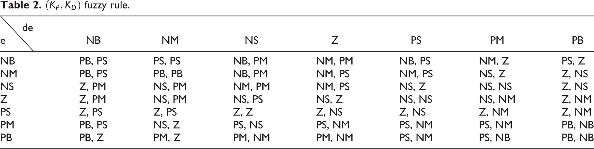
In Table 2,
The robot dynamics equation can be expressed by the following T-S fuzzy model, which is described by the IF-THEN rules as:
The rule i:

where
T-S model is a weighted sum of multiple linear models, which can approximate a nonlinear system. In equation (5), each T-S fuzzy rule describes a linear subsystem and the consequent output can be expressed by a linear function. According to the anti-fuzzification definition of the fuzzy system, the total output of the fuzzy model constructed by the fuzzy rules in equation (5) is

where wi
denotes the membership function of the ith rule, which represents the weight of the rule i in the rule base. And it satisfies
A T-S fuzzy model is built by substituting data, which can use the following three rules to describe the dynamic behavior of the system

where

PDC controller design
PDC is a fuzzy controller design method based on T-S fuzzy model proposed by Tanaka and coworkers. 22 It is suitable for solving the nonlinear system control problem based on the T-S fuzzy model. The basic principle of this method is to design an independent linear state feedback controller for each local linear subsystem. The control rules of each linear subsystem and the corresponding fuzzy system have the same number of rules and the antecedent description. Finally, the global system controller is obtained by fuzzy weighting of the membership function. The total controller output of the whole system is the weighted set of each subsystem controller. Figure 2 describes the PDC design principle.
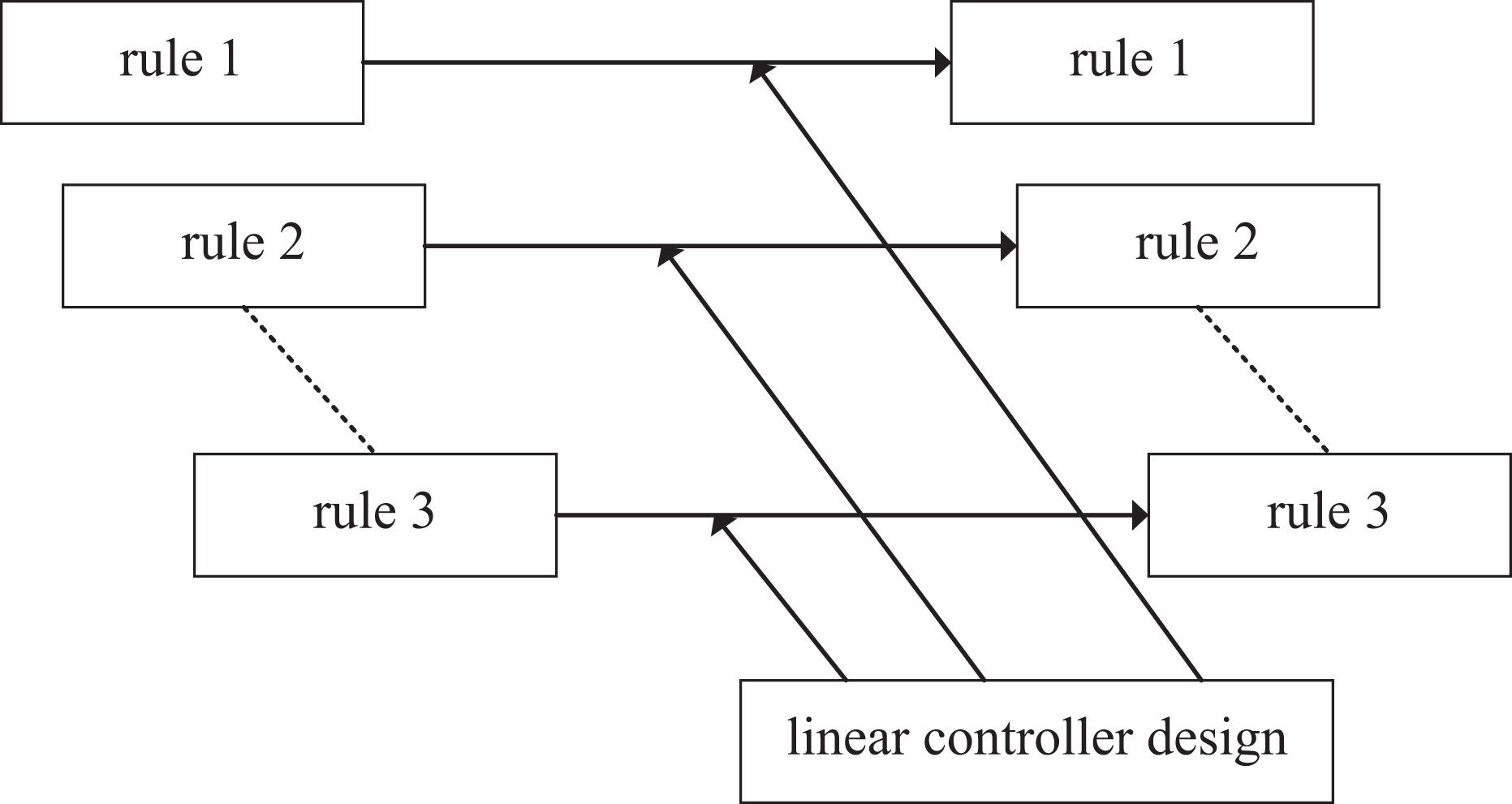
PDC design principle. PDC: parallel distributed compensation.
For each T-S fuzzy rule, through the state feedback method, if-then fuzzy rules of the controller can be expressed as follows:
The rule j:
if

where
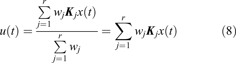
According to the description of the PDC method, by weighted average sum of the linear controllers of all subsystems, the T-S fuzzy controller of the system equation (6) can be obtained as
The FMB control system is a closed-loop system composed of a T-S fuzzy model and a fuzzy controller. The T-S fuzzy model is used to represent a non-linear controlled object.
23
The fuzzy controller can process the state vector

FMB control system block diagram. FMB: fuzzy model-based.
Considering that the membership function has the properties shown in the equation (9)

Therefore, according to the equations (6), (8), and (9), the total output of the FMB closed-loop control system can be expressed as follows

Stability is an important attribute of the control system, and it is also a necessary condition for the normal operation of the system. Next, the stability conditions of T-S fuzzy system based on the Lyapunov function are inferred and analyzed using linear matrix inequality (LMI) tools.
Construct the Lyapunov function as

where
Derivation of the time t by the Lyapunov function yields the equation

Substituting the closed-loop system equation (10) into equation (12)
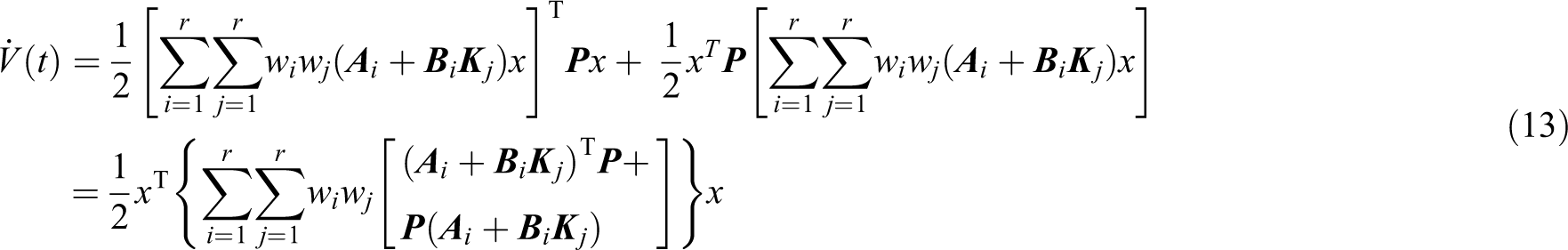
Simplifying the equation (13)

Therefore, satisfy

Define

If define

The solution of the inequality equation (17) is a convex optimization accessibility problem of LMI. By using MATLAB’s LMI toolbox, the positive definite matrix

Q-learning algorithm
Q-learning algorithm is an iterative incremental online learning method. It can make the agent have the ability to select the optimal action sequence of the Markov decision process through interaction with the external environment. 24,25 Figure 4 shows the principle of the Q-learning algorithm.

Q-learning algorithm principle.
The agent receives the input st
in the environment and outputs the corresponding action at
through an internal reasoning mechanism. The environment becomes a new state
The purpose of this algorithm is to learn the return value

where
This article selects Q-learning method for trajectory planning, obtains the ideal trajectory of the end of the manipulator and achieves the optimal path of the workspace. The external environment is discretized into a 6 × 6 × 2 grid map, and the vertices of each cube are a corresponding state. The end of the manipulator has six kinds of actions, including top, bottom, left, right, front, and back in each state. The control of the corresponding movement are respectively denoted by
The obstacle area is Sd , the desired position is St , the safe area is Ss , then the reward function is expressed as follows

Trajectory planning flow chart is shown in Figure 5. The pseudocode of the Q-learning algorithm is shown in Table 3. The end condition are as follows: 1. Reach the max steps; 2. Reach the obstacle; 3. Reach the goal.
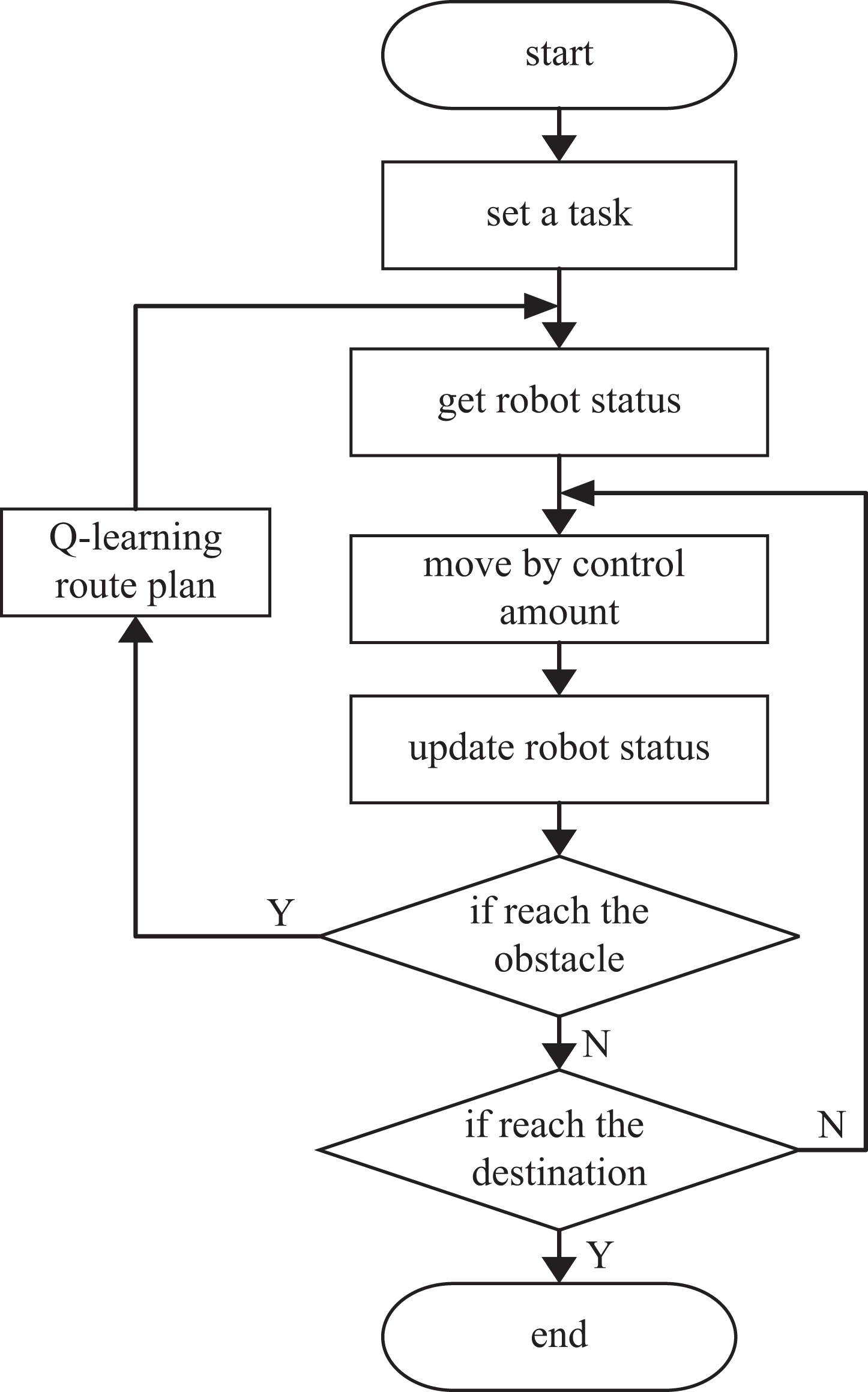
Trajectory planning flow chart.
Q-learning algorithm.

Simulation research
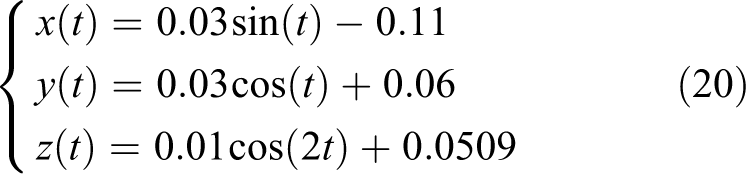
This section studies the trajectory tracking of right arm of the robot NAO. The simulation environment is MATLAB 2014a and the simulation time is set to 10 s. The selected end desired trajectory is shown in equation (20)
Without-interference simulation
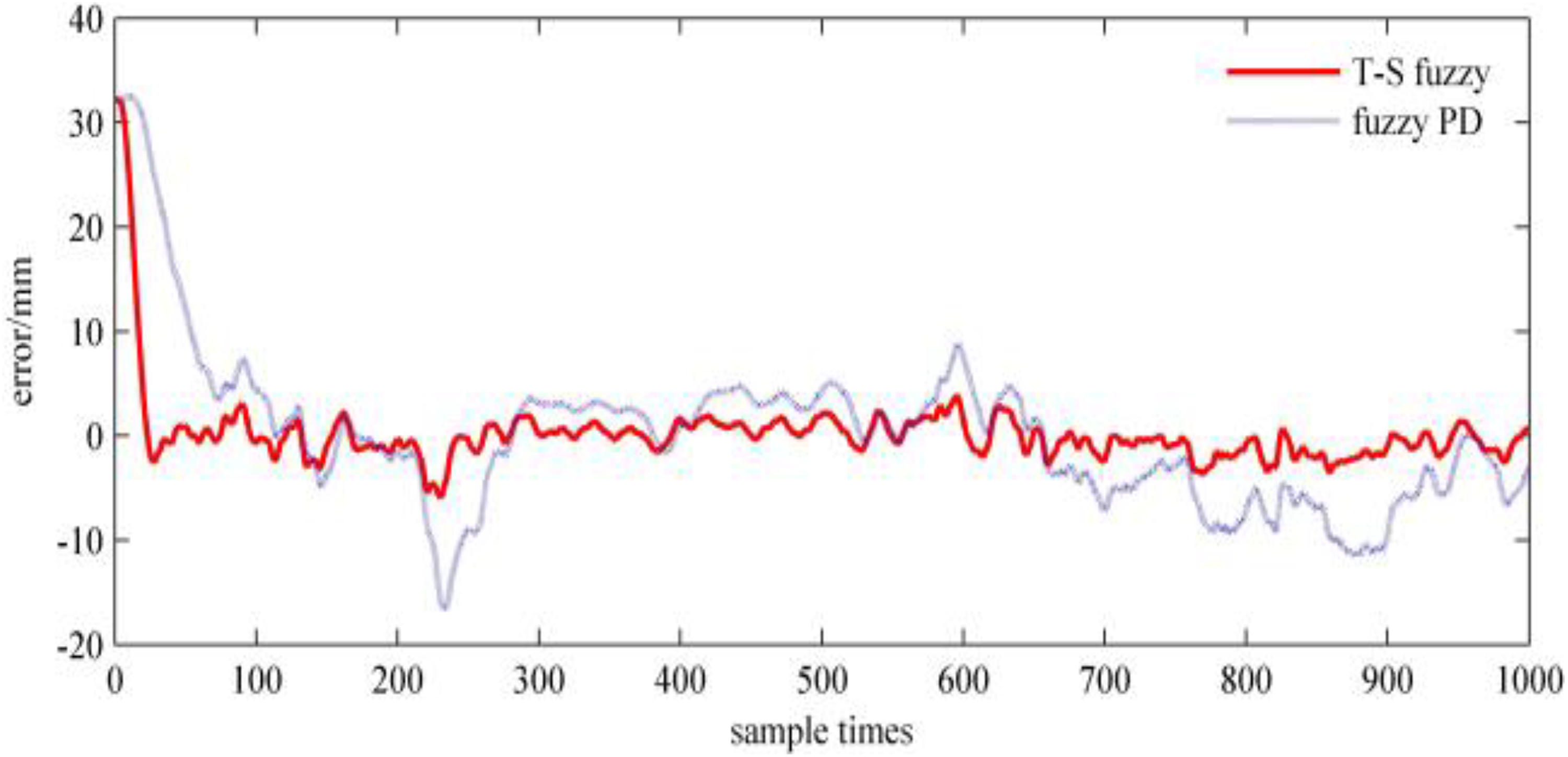
The tracking curve of the fuzzy PDC controller control effect based on the manipulator T-S fuzzy model is shown in Figure 6. As a comparison, the tracking curve of the fuzzy PD controller is shown in Figure 7.

The end tracking curve without interference using T-S fuzzy control. T-S: Takagi–Sugeno.

The end tracking curve without interference using fuzzy PD control. PD: proportional–derivative.
In Figures 6 and 7, both control schemes can make the end of the manipulator track the curve of the equation (20) well under the condition of without interference. Especially in the T-S fuzzy control scheme, the tracking curve basically fits the desired curve. The change of the joint driving torque using T-S fuzzy control is shown in Figure 8.

The change of driving torque of the joint using T-S fuzzy control without interference. T-S: Takagi–Sugeno.
To demonstrate the improved effect more intuitively, the position error of the end effector in each axis direction of the 3-D coordinate system is given. Figures 9, 10, and 11 are the error of the actuator, respectively, relative to the desired trajectory on the x-axis, y-axis, and z-axis.

The end effector error comparison in x-axis without interference.
The end effector error comparison in y-axis without interference.

The end effector error comparison in z-axis without interference.
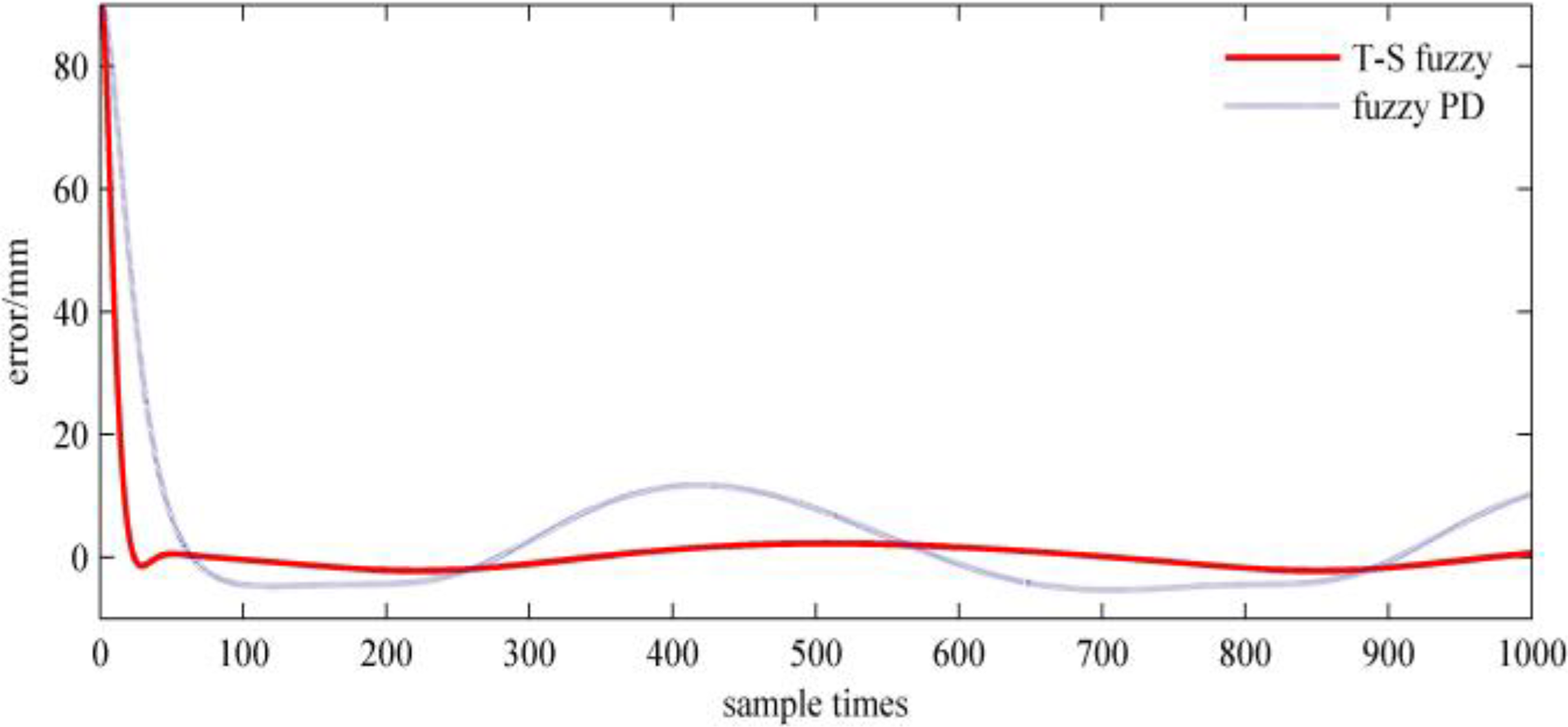
In Figures 9 to 11, comparing with the fuzzy PD algorithm, T-S fuzzy control algorithm can make the position error converge near 0 in a short time, which significantly reduces the tracking error of the end effector and effectively improves the control performance of the manipulator.
Interference simulation
The above control scheme is performed without interference, and it is an ideal model. However, in practice, it is inevitably subject to disturbance caused by the robot’s own frictional resistance and external noise. Therefore, Gaussian white noise is added to the control system, which can simulate the actual work environment and study the control effect of the proposed algorithm under the interference environment.
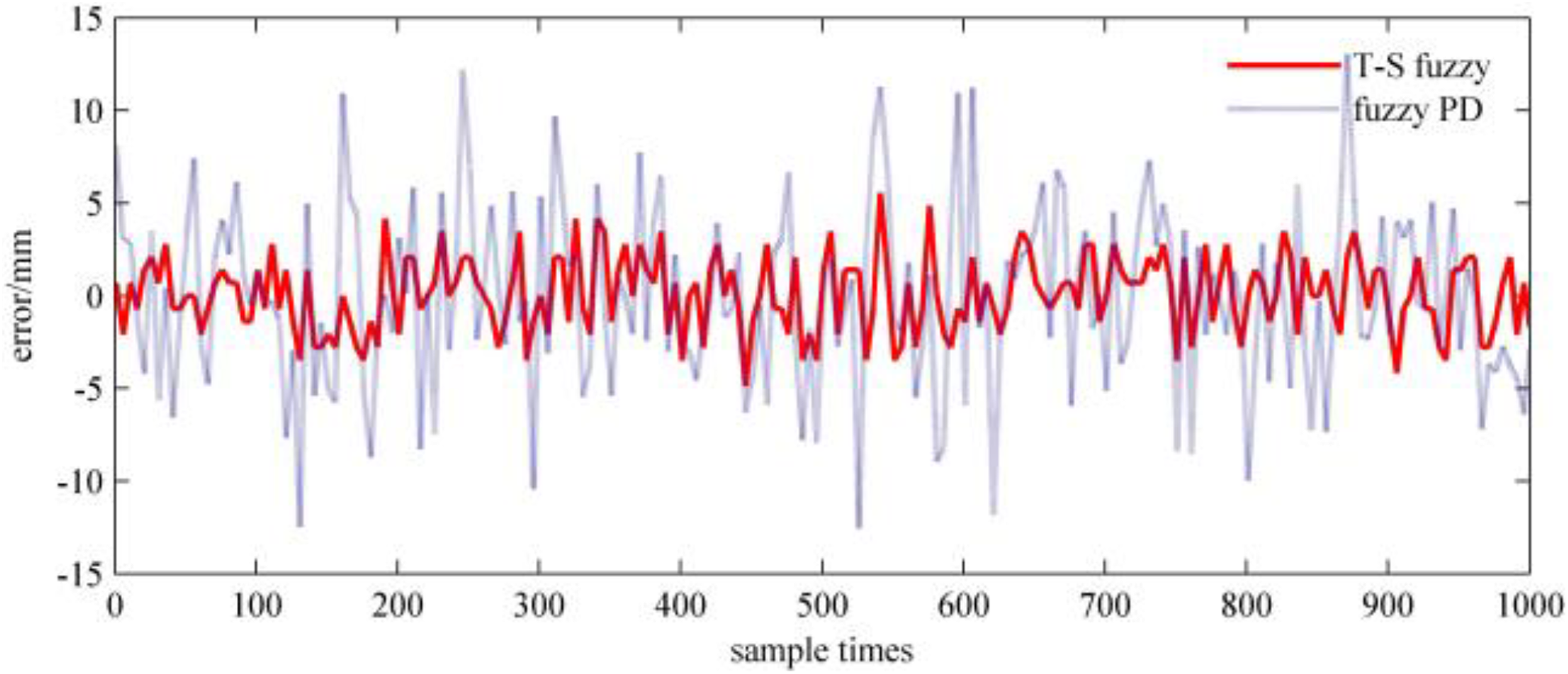
The desired trajectory in equation (20) is still used as the Gaussian noise signal with a mean value 0 and variance 1 is added, and the other parameters consisting of the noise-free environment is kept. The tracking curve based on T-S fuzzy model using fuzzy PDC control is shown in Figure 12, and the tracking curve of the fuzzy PD controller is shown in Figure 13.

The end tracking curve with interference using T-S fuzzy control. T-S: Takagi–Sugeno.
The end tracking curve with interference using fuzzy PD control. PD: proportional–derivative.
In Figures 12 and 13, control schemes are influenced by noise. For the T-S fuzzy control scheme, the end effector can also basically track the desired trajectory curve. There’s a certain trajectory deviation comparing with the Figure 6, but it cannot affect the system to complete the task in the allowable range of error. At this time, the fuzzy PD controller is seriously disturbed by noise. It shows poor stability, and there are more offset expectations of tracking trajectory. The system cannot complete the trajectory tracking task with high precision.
Fuzzy control change of driving torque of each joint is shown in Figure 14. Comparing with Figure 8(a) to (c), respectively, it can be seen that the control torque of each joint in Figure 14 (a)to (c) is affected by noise and output jitter occurs near the stable value. Among them, the influence of two roll joints rotating around the z-axis is more obvious. Under interference situation, the desired trajectory errors of the end effector of the manipulator on the x-axis, y-axis, and z-axis are shown, respectively, in Figures 15, 16, and 17.

The change of driving torque of each joint without interference using T-S fuzzy control. T-S: Takagi–Sugeno.
The error of the end effector on x-axis with interference.

The error of the end effector on y-axis with interference.
The error of the end effector on z-axis with interference.
Quantitative analysis
To quantitatively analyze the tracking effect of the end effector using T-S fuzzy controller and the fuzzy PD controller respectively, the formula for calculating the average tracking error of the algorithm is defined as in the equation (21)

where E represents the average tracking error, and E
1 and E
2, respectively, represent the average tracking error of the T-S fuzzy control algorithm and the fuzzy PD control algorithm. α represents the expected value of each coordinate axis. β represents the actual tracking value of each coordinate axis, and
In addition, I is the improvement precision of T-S fuzzy control compared with the fuzzy PD control. The calculation formula is shown in equation (22)

The table of control accuracy can be calculated as shown in Table 4.
The control accuracy table.

Experiment study
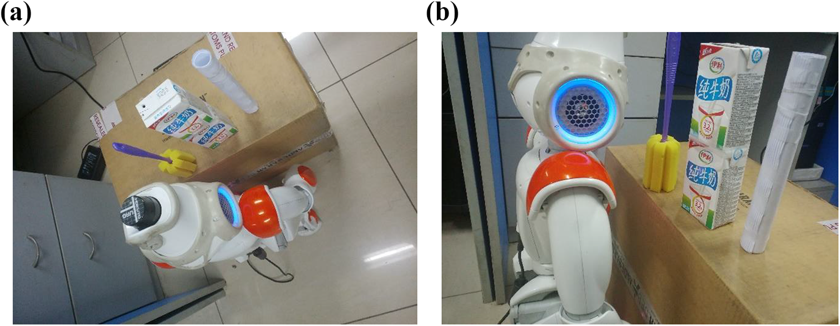
NAO-H25 robot is used to perform the grabbing experiments. The experimental task is to control the robot right arm to move along the non-collision optimal path and grab the target object, which can verify the feasibility of the trajectory planning Q-learning algorithm. The experiment scene is shown in Figure 18. A cylindrical rod is used catching target, and the brush and the milk carton, respectively, are used as the obstacle 1 and the obstacle 2. Considering the length of the manipulator, the three objects are placed on a diagonal line, and the robot begins to plan path when facing the obstacle 1.
The grasping experiment scene.
The rod is placed on the experiment platform, so that the robot’s camera can see the whole target. Then the contour learning in the visual development tool Choregraphe [version:1.14] is used to scan the target object for contour recognition. The object data identified is named object and sent to the robot. Figure 19 shows the contour recognition of the target object.
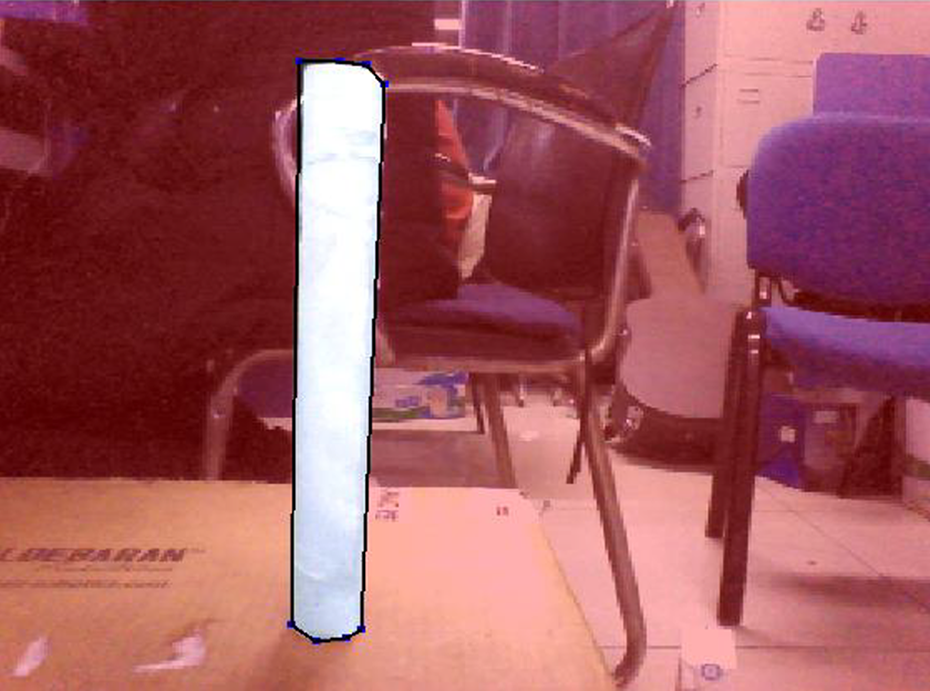
The contour recognition of the target object
The laser on the head of the NAO robot can measure the position of the objects and the obstacles in the environment. 26 Firstly, a laser positioning is performed on the target object, and the Laser-Monitor monitoring window is opened. The obtained result of target scanning is shown in Figure 20. Then, the obstacles 1 and 2 are added to the scene, and the robot performs laser positioning of the obstacle. The scanning result is shown in Figure 21.

Target’s laser scan results.

Obstacle laser scan results.
The center of the robot is used as the original coordinate, and the 3-D coordinate system shown in Figure 22 is established, which can calculate the position of the radar scanning result.

NAO robot coordinate system.
The Q-learning obstacle avoidance is implemented using Python 2.7, and the T-S fuzzy controller designed in the third section is used for trajectory tracking control. The grasping process of 3-D virtual robot in Choregraphe is shown in Figure 23.

The virtual robot grasping process in Choregraphe.
The practical grasping process is shown in Figure 24. Figures 23 and 24 show the manipulator needs to avoid the obstacles 1 and 2 to grasp the target. According to the planned path using Q-learning algorithm, the end effector can change the direction of the movement when it collides the obstacle. By using T-S fuzzy PDC controller, it can accurately reach the location of the target along the planned path and successfully grasp the target.

Physical robot grasping process.
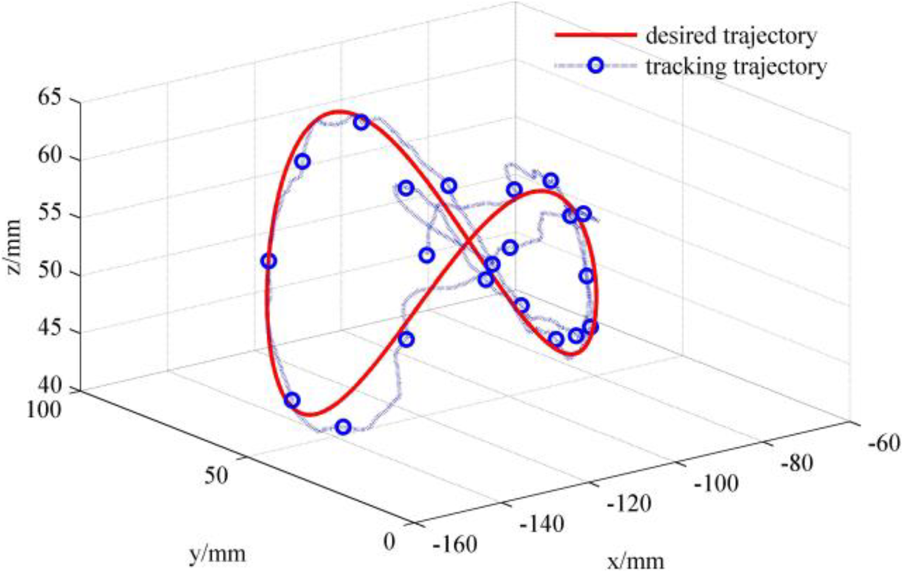
The whole trajectory of the end effector of the manipulator in this experiment is shown in Figure 25. The trajectory of the planning path using the Q-learning algorithm is shown in Figure 26. In Figures 25 and 26, the red prism represents the obstacle and the green column represents the target, and the change of the trajectory of the end effector can be clearly shown.

The whole grasping trajectory of end effector.

The trajectory of the planning path.
Conclusion
In this article, aiming at the obstacle avoidance problem of NAO right arm, a method of enhanced Q-learning collision-less trajectory planning based on fuzzy PDC structure is proposed, which achieves the autonomous grasping to avoid obstacles. Firstly, the T-S fuzzy model of the manipulator is built, then a closed-loop fuzzy controller is designed based on the T-S fuzzy model to reduce the tracking error and analyze the stability of the closed-loop system. Finally, based on the fuzzy PDC control structure, the Q-learning algorithm is proposed to make the action strategy, and the obstacle avoidance trajectory is planned. The simulation and experiment results show that the proposed algorithm can effectively achieve the manipulator movement control and make the manipulator complete the grasping task successfully, which verifies the feasibility of the algorithm.
Future work will consider increasing the pose control of joint and designing motion grasping algorithms for dynamic environments, further extending the application scenario of humanoid manipulator.
Footnotes
Declaration of conflicting interests
The author(s) declared no potential conflicts of interest with respect to the research, authorship, and/or publication of this article.
Funding
The author(s) disclosed receipt of the following financial support for the research, authorship, and/or publication of this article: This work is supported by the National Natural Science Foundation of China projects (No. 61773333, No. 61473248, No. 61573305) and the Key Projects for Scientific and Technological Research in Colleges and Universities in Hebei Province (ZD2016150).