
Abstract
In order to promote building intelligence and solve the disadvantages of traditional grouting technology, the trajectory planning of closed-loop grouting robot was designed. The minimumsnap optimization function was used to optimize the A* algorithm to realize the 2D trajectory planning, which could obtain a smooth, continuous route, and planning diagram of time distribution, speed, acceleration, and jerk. Further, the weight function of the improved A* algorithm was adjusted to perform 3D trajectory planning to reduce redundant nodes in the route. A new approaching law adaptive sliding mode control method was used to achieve precise trajectory tracking of the robotic arm and reduce the problem of chattering in sliding mode control. Through the design of closed-loop grouting robot and the research of trajectory planning, the two-dimensional and three-dimensional paths of grouting robot could be optimized. The system could realize automatic grouting operation. It could promote the development of high efficiency and safety in the construction grouting industry.
Keywords
Introduction
With the rapid development of building intelligence, the introduction of construction robots is the only way for the development of the construction industry. 1 The traditional grouting technology is mostly constructed by hand-held or low-automation equipment, the grouting efficiency is low and the grouting quality cannot be guaranteed. Especially when working at high altitude, the risk coefficient is high and the workers are required to have high experience.2,3 At present, in view of the complex building environment, there is no systematic grouting robot on the market. Therefore, it is necessary to study the design and trajectory planning of closed-loop grouting robot. Through the design of closed loop structure, the research of two-dimensional trajectory planning and three-dimensional trajectory planning, the autonomous motion planning of grouting robot can be realized. The grouting task can be completed. The grouting success rate and grouting quality can be improved. It is of great significance to the development of the construction industry. 4
The grouting construction robot needs to be designed, which including the robot structure, grouting process, 2D trajectory planning of robot, 3D trajectory planning of robotic arm, and trajectory tracking. In recent years, Wagner et al. 5 proposed a new method of robot manufacturing in the construction industry, which made the traditional process and professional automation technology synergize, which was conducive to product quality and productivity. Wang et al. 6 used synchronous positioning, mapping technology, and instance segmentation methods to enable the robot to cope with complex field conditions. Saeed et al. 7 proposed a boundary node method to solve the path planning problem in the static environment. Qian et al. 8 implemented a method for robot path planning optimization based on heuristic multi-direction rapid exploration tree. Song et al. 9 proposed an improved cuckoo search algorithm for three-dimensional path planning. Gole et al. 10 proposed to use the firefly swarm optimization algorithm for UAV path planning. Rebouças Filho 11 optimized trajectory tracking control based on global genetic algorithm. Liu et al. 12 proposed an adaptive neural network control method with less calculation to track the robot’s motion. At present, although the development of path planning and trajectory tracking technology is relatively mature, the systematic algorithm design of the grouting robot needs further improvement and adjustment to achieve better process results.
The rest of this article is arranged as follows. The second part is the system design. It mainly improves the grouting quality and construction safety by designing the closed-loop structure of grouting robot and grouting technology. The third part is the 2D path planning. The A* algorithm is optimized by the minimum snap optimization function to obtain the two-dimensional path planning of grouting robot. The fourth part is the 3D path planning. Through further adjustment of the distribution of the improved A* algorithm weight function, the three-dimensional path planning of grouting robot can be obtained. The fifth part is the trajectory tracking. Through the adaptive sliding mode control method of the new approach law, the trajectory tracking of the manipulator is realized and the control accuracy of the system is improved. The sixth part is the experimental test. The seventh part is the conclusion.
System design
System structure
In this paper, a closed-loop automatic grouting robot was designed. The structure diagram is shown in Figure 1. The grouting port and the grout outlet are in a closed loop of slurry circulation by designing a closed-loop non-stop-flow terminal grouting system, which can increase the success of grouting and ensure the stability and controllability of grouting quality.

Schematic diagram of grouting robot structure.
System technology
The process flow chart of the robot closed-loop automatic grouting system is shown in Figure 2.
Step 1: The grouting robot system uses the BIM (Building Information Modeling) modeling information to roughly locate the position of the grouting inlet and outlet. Through the virtual three-dimensional model of construction engineering, the approximate position of the grouting opening can be obtained. The target grouting opening position can be restricted within a certain error tolerance range.
Step 2: The grouting robot system uses algorithms for trajectory planning and obstacle avoidance. According to the rough positioning information of the grouting port, the system controls the robot to move to the operating range of the manipulator, and controls the grouting manipulator to drive the grouting pipe to move.
Step 3: The accurate position of the grouting port can be detected by the high-definition camera, after the robot moves to the working range of the manipulator. The system drives the manipulator to insert the grout pipe into the grout inlet and grout outlet respectively to form a sleeve grout loop.
Step 4: Start the grouting process. After the grouting starts, the grouting robot can real-time detect and calculate the amount of mud that has been injected into the steel sleeve by using the corresponding components, such as mud flow meter and mud level meter. Because the specification and size of the rebar sleeve are unified, we can judge whether the grouting stops by comparing the amount of mud that has been filled into the sleeve and the volume of the cavity of the rebar sleeve.
Step 5: After the grouting is finished, the grouting robot system drives the grouting manipulator back and make the plugging manipulator to clamp the plunger for sealing the grout inlet and the grout outlet.
Step 6: After completing the grouting task of the steel bar sleeve, the grouting robot uses the visual inspection technology to determine whether there is any ungrouted steel bar sleeve. If an ungrouted sleeve is detected, the grouting robot will repeat the above grouting process until all the rebar sleeves have been grouted. Then the grouting task is over.

Flow chart of system process.
2D trajectory planning
A* path planning
Path planning is one of the main research contents of motion planning. It uses a certain search strategy to find a collision-free continuous path from the start point to the end point in the designated navigation map. 13 In the prefabricated building environment, the path planning of the mobile robot for the autonomous operation stage is based on the principle of the shortest path. And the collision-free path can be found in the BIM modeling environment. 14
A* algorithm is the most effective direct search method for solving the shortest path in a static road network. 15 The formula is

Where:
The search strategy based on the A* algorithm is shown in Figure 3. In the BIM grid navigation map, there are a total of six types of grids, which are the starting point, the ending point, the current node, the immediate child nodes of the current node, the feasible node, and the obstacle node. There are eight child adjacent nodes around each current node, representing the feasible movement direction of the mobile robot. 16 When considering the three-dimensional space, there are 26 sub-adjacent nodes around.
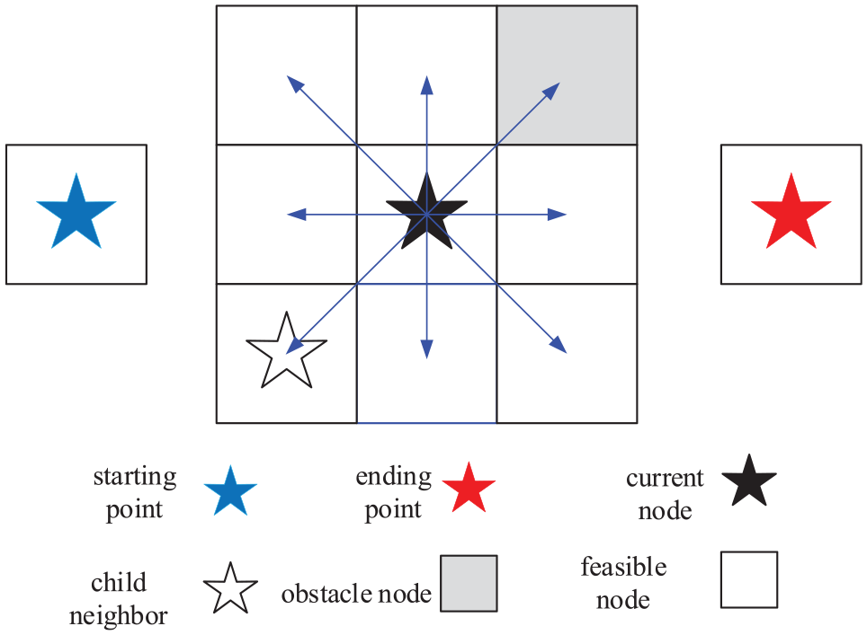
A* algorithm grid map.
Minimum snap trajectory optimization
The results of traditional path planning are mostly a set of planned route maps from the start point to the end point without information such as time, speed, and acceleration. In addition, the result of path planning has a large number of non-smooth inflection points, which have disadvantages, such as high energy consumption and instability. They are not conducive to the positioning and control of the construction robot’s trajectory. 17 The trajectory generated by the Minimumsnap is smooth and energy-saving. Therefore, you can generate a smooth, continuous trajectory including time distribution, speed, acceleration, and jerk by using the minimumsnap optimization function to constrain the path planning.
The objective function to minimize in Minimumsnap is snap. In order to construct the energy loss function of the quadratic programming, the position function in any direction of the trajectory needs to be described as a seventh order eighth order polynomial. The polynomial of the trajectory can be expressed as

When the initial trajectory is segmented, as shown in Figure 4. According to the path points, the trajectory is divided into N segments. The distance of each segment is calculated. The total time T is equally divided by the distance to obtain the time sequence.

Segmented trajectory diagram.
The optimization function built by Minimumsnap is

Construct an constraint equation. The position, velocity, acceleration, or higher of a certain point are set to a specific value, which can constitute an equation constraint. Those values construct the same equation constraint for the position of the intermediate point due to passing the intermediate point.
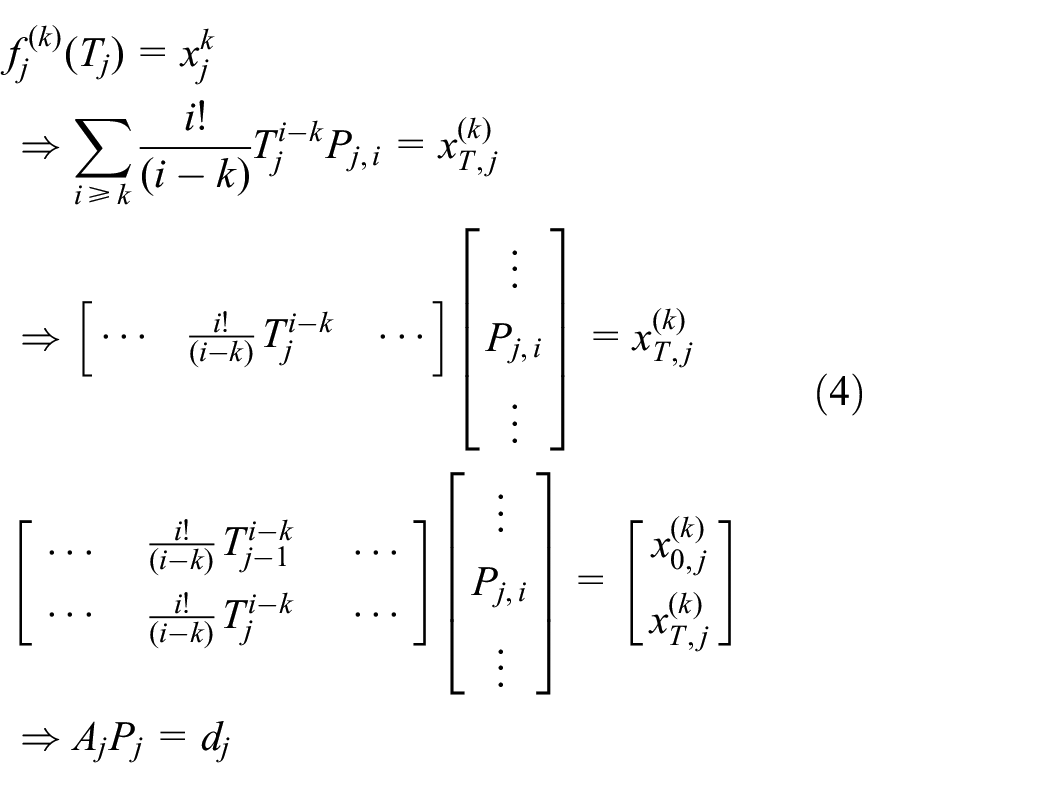
Construct a smoothness constraint equation.

Simultaneous formulas (3)–(5), using the quadprog() function in MATLAB to find the state quantities in all directions of the entire trajectory, the visualized results of path optimization in the BIM map environment are shown in Figure 5. Obstacles were randomly generated in a 30 × 30 × 10 xyz three-dimensional grid map. Set the starting point to [2, 2, 0] and the end point to [28, 28, 0]. The speed, acceleration and jerk of the starting point and the end point were all 0. The overall planning time was set to 20 s. The results showed that there were 32 segments in the trajectory planning. The partial zoomed-in results can be seen in Figure 5(b). The red optimized trajectory is better than the original black trajectory, achieving smooth continuity of the trajectory. At the same time, the experiment obtained time distribution, velocity, acceleration, and jerk. The visualization result is shown in Figure 6.
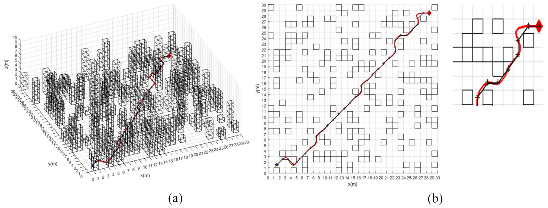
Visualization of trajectory planning: (a) 3D visualization and (b) 2D visualization.

Schematic diagram of trajectory planning results: (a) time distribution diagram, (b) speed visualization, (c) acceleration visualization, and (d) visualization of jerk.
3D trajectory planning
Improved A* algorithm
After the construction robot moving to the vicinity of the grout port, the robot system controls the movement of the mechanical arm and plans the three-dimensional movement route of the manipulator through the algorithm. The 3D path planning of the manipulator is more complicated than the 2D path planning of the robot for the prefabricated building space environment. There are still many redundant nodes, after using minimumsnap to smooth the three-dimensional path. Moreover, the generation path is long and the energy consumption is large. 18 By adjusting the weight function distribution of the A* algorithm, the path planning can be made faster and the redundant nodes in the path expansion process can be reduced. The established evaluation method is as follows.

In formula (6), a is the weight of the actual cost g(n) to reach the current node. And b is the weight of the estimated cost h(n) from the current node to the target node. The sum of the two weight coefficients is 1. With the expansion of real-time nodes, when the impact factor of g(n) becomes smaller and smaller, the impact factor of h(n) becomes larger and larger. It can achieve the purpose of balancing heuristics and shorten the path length and time.
Simulation analysis
In this paper, simulation experiments were conducted in Matlab2018 software. Divided the environment information into a grid of 10 × 10 × 10, taking the starting point coordinates (1, 1, 2) and the end point coordinates (10, 10, 8). The improved algorithm and the original algorithm were used for three-dimensional overall path planning. The simulation results are shown in Figure 7. Figure 7(a) is a 3D simulation view, and Figure 7(b) is a 2D view. It can be clearly seen from Figure 7 that the red path is better than the black path. The improved algorithm optimized the path and reduced redundant nodes, which was better than the original algorithm.

Experimental simulation results: (a) 3D view and (b) 2D view.
To further verify the superiority of the improved algorithm, dynamic obstacles can be randomly generated in the map during the simulation experiment. In the overall three-dimensional trajectory planning of the robot, when a dynamic obstacle was detected, it would give priority to local path planning and perform dynamic obstacle avoidance. After the obstacle avoidance was completed, performing overall 3D path planning again. The simulation result is shown in Figure 8, Figure 8(a) is a 3D view, and Figure 8(b) is a 2D view. It could be clearly seen from the experimental simulation results that when dynamic obstacles were randomly generated in the map, the path generated by the improved algorithm was still better than the original algorithm.
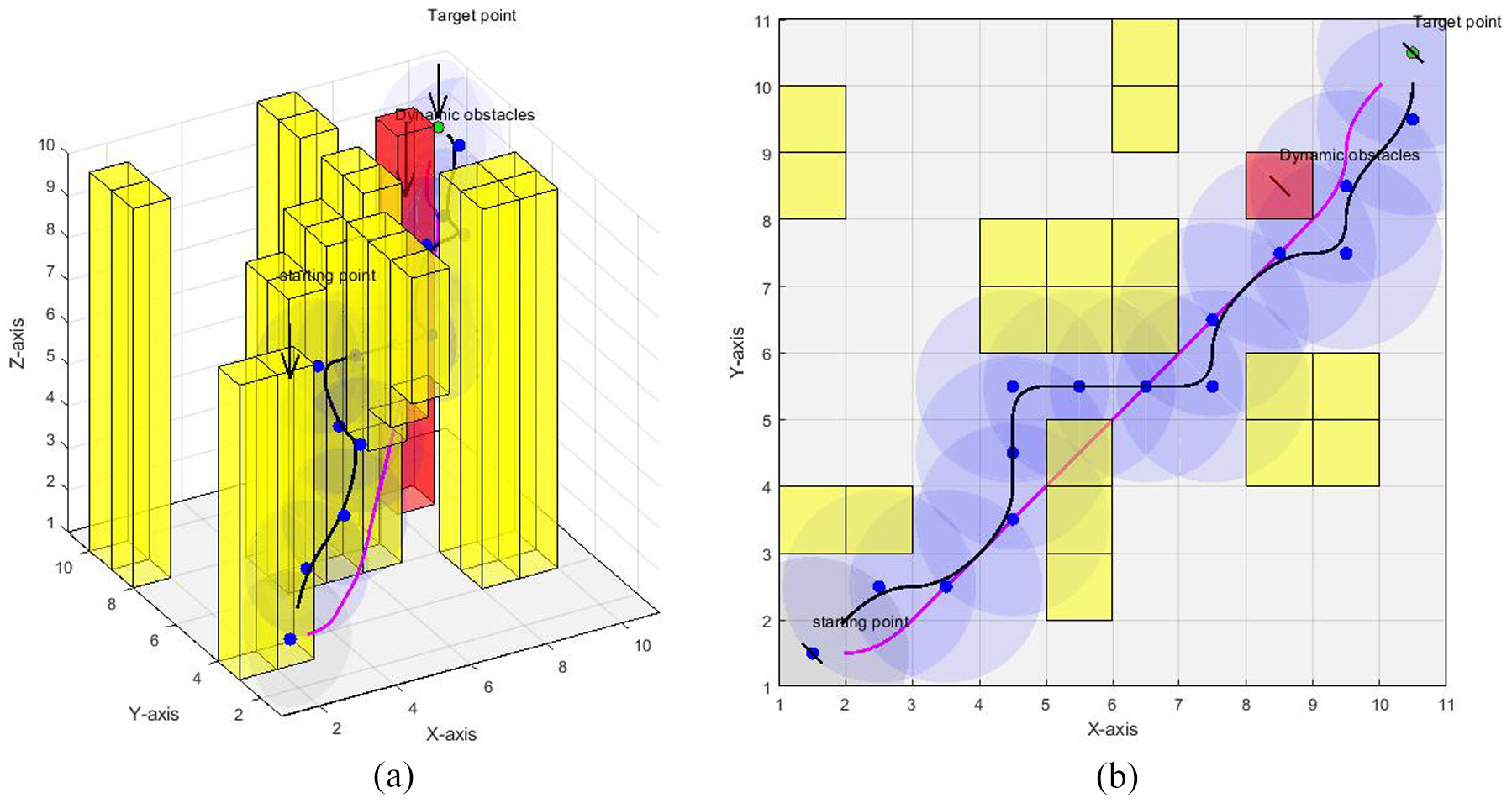
Experimental simulation results (including dynamic obstacles): (a) 3D view and (b) 2D view.
Trajectory tracking
During the motion control process of the robotic arm, the robot system is difficult to accurately realize the three-dimensional trajectory tracking of the robotic arm due to various uncertain factors such as modeling errors and external interference.19,20 This paper proposed a new approaching law adaptive sliding mode control method, using nonlinear interference observer to observe observable interference, estimating and compensating for unobserved interference through adaptive law design. The sliding mode control law was designed by using the method of improving the reaching law. In this way, the chattering could be improved and the control accuracy of the system will be better.
System structure design
Based on Lagrangian dynamics, an n-joint manipulator was designed, in which the dynamic performance is expressed by the second-order nonlinear differential equation as

Where:
In order to verify the new approaching law adaptive sliding mode control method, the two-joint manipulator was used as the experimental object. The structure diagram is shown in Figure 9. And the system control structure diagram is shown in Figure 10.
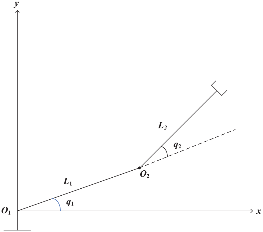
Two-joint robotic arm model.

System control structure diagram.
Controller design
Design of interference observer
In this paper, a nonlinear interference observer is used to estimate the composite interference. The estimated output is predicted by the difference between the estimated output and the actual output.

Where:
The dynamic equation of the observer system error is

After adopting the interference observer, the original system becomes

Design of sliding mode controller
The traditional synovial variable structure control is shown in Figure 11. When the state track reaches the sliding surface, it is easy to pass back and forth on both sides of the sliding surface and cause vibration. The synovial function is

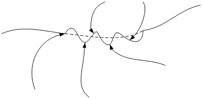
Dynamic diagram of synovial control.
Aiming at the chattering problem of sliding mode control, a new sliding mode control reaching law is proposed.


In the formula, when |s| ≤
Design of control rate
From equation (11), (14) can be obtained:

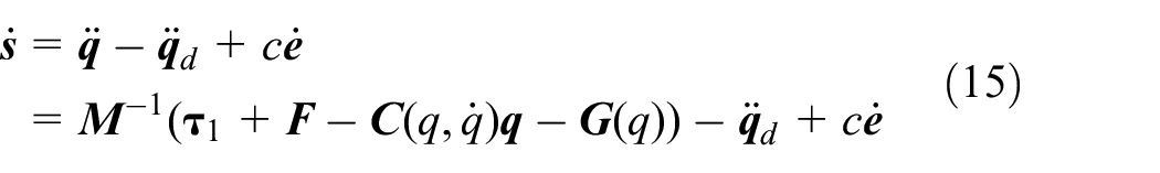
From equations (10) and (12), (15) can be obtained:
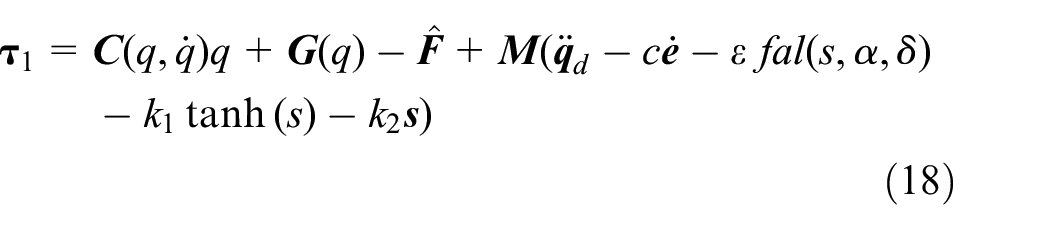
So the control law was chosen as

Design of adaptive law
Based on the design of the sliding mode controller, this paper introduces an adaptive algorithm. Estimate the unobservable part of the external disturbance signal

According to the above formula, design the control law of the robotic arm:
The adaptive law is:
Stability analysis
For the entire closed-loop system, it can take the Lyapunov function V:
Derivation of equation (18) can be obtained:

Substituting equations (9) and (16)–(19) into

When |s| ≥ δ

When |s| ≤

Because
Simulation experiment
Using simulink to simulate the designed controller in MATLAB, this article took the dynamic model of the two-joint robotic arm system as an example. The simulation results are shown in the figure below.
It could be seen from Figures 12 and 13 that when the new reaching law was used, the system used an interference observer and an adaptive law to compensate for interference. The position and speed tracking performance of joints had been improved, which improved the tracking performance of the system. It could be seen from Figures 14 and 15 that the design of the new reaching law made the control input continuous and smooth, weakening the chattering problem in sliding mode control, see Figure 15 for Joint control input of the method in this paper.

Joint tracking based on exponential approach law: (a) joint position tracking and (b) joint angular velocity tracking.

The method of this paper joint tracking: (a) joint position tracking and (b) joint angular velocity tracking.

Joint control input based on exponential reaching law.
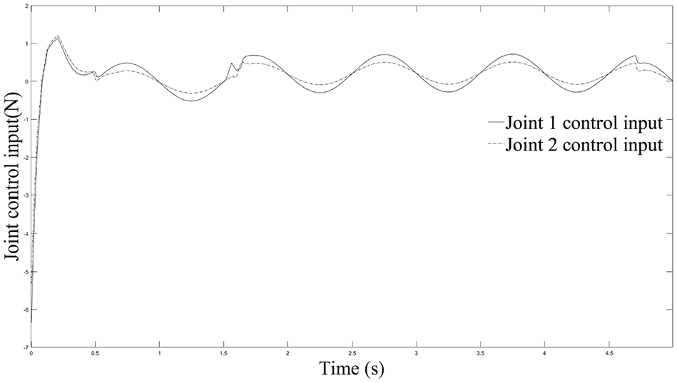
Joint control input of the method in this paper.
It could be seen from Figure 16 that the use of interference observer and adaptive law had a better compensation effect for external interference. And it could be seen from Table 1 that the design of disturbance observer and adaptive law reduced the input range of control torque. Therefore, the adaptive sliding mode control method of the robotic arm designed in this paper based on the new reaching law. In the robotic arm system, it could not only accurately track the trajectory, but also better deal with the influence of external interference and the uncertainty of the system’s internal parameters on the robotic arm system.
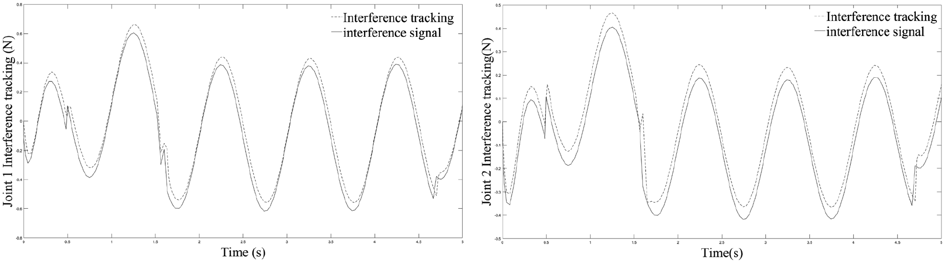
The method of this paper joint interference tracking.
Comparison of experimental data before and after algorithm improvement.

Experimental test
In order to verify the accuracy of the relevant algorithms in this article, in which Turtlebot 2i was taken as the experimental object. As shown in Figure 17, map modeling, trajectory planning, and robotic arm movement were performed respectively.

Turtlebot 2i robot.
The robot performed a slam modeling map. The experimental environment is shown in Figure 18.

Experimental environment: (a) actual map environment and (b) slam map environment.
Using minimumsnap to optimize A* algorithm for two-dimensional path planning, this experiment simulated on the Rviz visualization platform in the ROS environment. The experimental results are shown in Figure 19. The smooth and continuous route could be obtained, which verified the effectiveness of the algorithm.

2D trajectory planning.
After reaching the vicinity of the grouting port, the robot needs to recognize the grouting plug and control the motion of the manipulator. This paper used 3D-binocular vision technology to recognize objects, as shown in Figure 20.

Target recognition diagram of rebar sleeve: (a) the third perspective and (b) target identification map.
The robot performed 3D path planning and trajectory tracking of the manipulator, after recognizing the object. As shown in Figure 21, the simulation was performed on the Rviz visualization platform of the ROS environment. And the actual experiments were performed to verify the feasibility of the algorithm.

Motion planning diagram of robotic arm.
Conclusion
A closed-loop automatic grouting robot structure and its grouting flow are designed. Through the closed-loop non-breaking end grouting feedback system, the grouting port and the grout outlet are in the closed loop of the slurry, which improve the grouting process and ensure the grouting quality Stability and controllability.
The grouting robot performs 2D path planning by using the minimumsnap optimization function to optimize the A* algorithm, which can obtain a continuous and smooth route, including time allocation, speed planning, acceleration planning, and jerk planning.
The grouting robot performs three-dimensional path planning. On the basis of optimizing the A* algorithm, further the weight function of the A* algorithm is adjusted to make path planning faster and reduce redundant nodes in the path expansion process.
A new approaching law adaptive sliding mode control method is proposed, which makes the robot arm more accurate when tracking the 3D path trajectory. This method can better deal with external interference and the uncertainty of system internal parameters.
The Turtlebot 2i robot is used to verify the related algorithms. The robot performs slam map modeling, 2D path planning, 3D path planning, and manipulator control motion, which verify the feasibility and superiority of the related algorithms. A preliminary analysis is made for the research of automatic grouting system of grouting robot.
Footnotes
Handling Editor: James Baldwin
Declaration of conflicting interests
The author(s) declared no potential conflicts of interest with respect to the research, authorship, and/or publication of this article.
Funding
The author(s) disclosed receipt of the following financial support for the research, authorship, and/or publication of this article: Thank you for the support of the Provincial Natural Science Research Project of Universities in Anhui Province with the project number KJ2019A0797. Thank you for the support of the Anhui Jianzhu University Ph.D. Foundation Project with the project number 2018QD42. Thank you for the support of the open fund scientific research project of the key laboratory of Sichuan universities and colleges with the project number GK201908.
Data availability statement
All data, models, and code generated or used during the study appear in the submitted article.