
Abstract
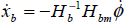
On-orbit rescuing uncontrolled spinning satellite (USS) using space robot is a great challenge for future space service. This paper mainly present a trajectory planning method of space manipulator that can track, approach and catch the USS in free-floating situation. According to the motion characteristics of USS, we plan a spiral ascending trajectory for space manipulator to approach towards USS in Cartesian space. However, it is difficult to map this trajectory into the joint space and realize feasible motion in joint space because of dynamics singularities and dynamics couple of space robot system. Therefore, we utilize interval algorithm to handle these difficulties. The simulation study verifies that the spiral ascending trajectory can been realized. Moreover, the motion of manipulator is smooth and stable, the disturbance to the base is so limited that the attitude control can compensate it.
Introduction
This paper deals with a special problem of tracking trjectory planning of space manipulator for capturing the uncontrolled spinning satellites. On-orbit capturing is a challenge work for space robot system in the future space service. The space robot science has gotten big progress in the past decade. Therefore, on-orbit service for uncontrolled satellite will be a main application of space robot in order to reduce the space cost in the future.
When human being launched the first space robot and operated it to accomplish the space mission, space robot began to be utilized in different space tasks. Nowadays space robots are aiding to construct and maintain the International Space Station (ISS) and servicing the space telescope. Therefore space robotic servicing for satellite such as rescue, repair, refuelling and maintenance, promise to extend satellite life and reduce costs, makes it one of the most attractive areas of developing space technology. Spacerobots are likely to play more and more important roles in satellite servicing mission and space construction mission in the future. The approach and capture operation must be solved firstly in order to accomplish all these missions. A well known space robot, the Shuttle Remote Manipulator System (SRMS or “Canadarm”) [D. Zimpfer and P. Spehar, 1996] was operated to assist capture and berth the satellite from the shuttle by the astronaut. NASA missions STS-61, STS-82, and STS-103 repaired the Hubble Space Telescope by astronauts with the help of SRMS. Engineering Test Satellite VII (ETS-VII) from NASDA of Japan demonstrated the space manipulator to capture a cooperative satellite whose attitude is stabilized during the demonstration via tele-operation from the ground control station [Kawano, I., et al. 1998], [Noriyasu Inaba, et al, 2000]. All mentioned above space robotic technologies demonstrate the usefulness of space robot for space servicing. However their use is limited to capture the satellites that are cooperative and attitude stabilized. For instance, the Spartan satellite lost its attitude control function and rotated at two deg/sec. NASA mission STS-87 tried to catch it using the SRMS in 1997, whereas the SRMS failed to capture this satellite. Therefore the capture and recovery of a valuable uncontrolled satellite can be a class of future mission for the future space robot.
Nearly all of satellite servicing missions occurred have been executed by Extra-Vehicular Activity (EVA) of the astronaut with the limited help of space robotic manipulator. It is very expensive and dangerous for the astronauts to capture an uncontrolled spinning satellite, even for the slowly spinning satellite. On the other hand, space robotic technology becomes more and more advanced recently. The space robot carries out such satellite servicing mission automatically or with limited human support in the future. However, the first step of the capture is how to track and approach the target satellite. Stephen Jacobsen et al [Jacobsen, S., et al. (2002)] presented to plan a safe kinematics trajectory for free flying robots approaching an uncontrolled spinning satellite, they address how to let the space robot approach to the workspace of robotic manipulator in which the manipulator can operate and capture the USS. Therefore, this paper assumes that the target satellite is in the workspace of space manipulator. it is desirable to contrive a new tracking and approach trajectory for space manipulator to capture the target satellite.
So far, there are many studies on trajectory planning of space robot. S. Dubowsky and M. A. Torres[S. Dubowsky and M. A. Torres (1991)] addressed path planning of space manipulator to minimize the disturbance to the space base. Evangelos Papadopoulos [E. Papadopouls (1992)] presented the nonholonomic behavior using to plan the path of space manipulator. Kazuya Yoshida and K. Hashizume[K. yoshida and K. Hashizume (2001)] utilized the ETS-VII as an example to deliver zero reaction maneuver by planning the manipulator's trajectory. Om P. Agrawal and Yangsheng Xu[Om P. Agrawal and Yangsheng Xu (1994)] introduced a global optimum path planning for redundant space manipulator. All examples mentioned above make the space robot as the research object to study its nature characteristics and interaction. However, only few researchers work on tracking trajectory planning of space manipulator for capturing the uncontrolled satellite in fact. Hiroyuki et al [Hiroyuki Nagamatus, et al. (1996)] presented a capture strategy for retrieval of a tumbling satellite by a space robotic manipulator. Zhenghua Luo and Yoshiyuki sakawa [Zhenghua Luo and Yoshiyuki Sakawa (1990)] discussed the control law of capturing a tumbling object by a space manipulator. Therefore, how to plan feasible tracking trajectory becomes more and more important problems. For instance, ETS-VII system has a six-DOF manipulator, this six-DOF manipulator based on space base is different with terrestrial manipulator in trajectory planning and control.
Hence it is necessary to plan the tracking trajectory of space manipulator for capturing USS from the engineering point of view. This paper aims to address an innovative tracking trajectory planning method of space robot manipulator capturing the USS according to the characteristics of USS. This paper is organized as follows. The section two describes the main problem and assumption, the section three simply reviews the kinematics and dynamics equation of space manipulator. Then, we address the motion estimation of USS in section four. The section five addresses our trajectory planning method. In section six, the computer simulation study and result are showed. The section seven summarizes the whole paper and educes the conclusion.
Problem Formulation
Description of Problem
On-orbit capturing USS has not successful examples so far, as a typical example of on-orbit operation. Here, the authors mainly assume a capture operation in order to describe the problem. Fig. 1 shows a schematic illustration of a tracking operation in which a space manipulator is tracking and approaching towards the target satellite. This operation can almost been solved for terrestrial robotic manipulator. However, in space environment, it is very difficult problem for robotic manipulator to capture USS because of the dynamics couple and dynamic singularities which result in the big error of desired trajectory and real trajectory, this error possibly causes the catastrophic affair and demolish the space robot system completely. On the other hand, it is very important problem to plan a trajectory for space manipulator to track and approach the USS. This paper will focus on this problem. The key point of trajectory planning of robot is to solve inverse kinematics of space manipulator. The drawback in kinematics problems of free-flying space manipulator is that, as Longman et al [R. W. Longman, R. E. LindBerg, and M. F. Zedd (1987)] and Vafa et al [Z. Vafa and S. Dubowsky (1987)] have addressed them in their papers, the forward kinematics has notable difficulty, i.e., the position and orientation of the manipulator end-effector do not have a closed form solution since they depend on the inertia property that changes according to the configuration of space manipulator. Therefore, the history of the postural change must be considered in order to derive the solution, all these problems make the inverse kinematics more difficult.

A schematic illustration of tracking operation in space
In order to cope with tracking trajectory planning problem, the present paper describes a tracking trajectory according to the features of the USS and the space manipulator. As discussed in detail in section five.
In this paper, the authors assume a model of space robot system which is composed of a space base and a robotic manipulator arm mounted on the space base. Fig. 2 shows a simple model of space robot system with a single manipulator arm. In order to clarify the point at issue, they present the following assumption.

Model of a space manipulator system
The space robot system consists of n+1 links connected with n active joints, each joint has one rotational degree of freedom (DOF) and is controlled. The attitude or position of the space base can be controlled or not be controlled respectively.
No mechanical restriction and external force or torque to the space manipulator system, i.e. the gravity is ignored, so that the total momentum of the mechanical system is always conserved. The kinematics and dynamics analysis during the motion is in the inertial coordinate system. Therefore, the DOF of the space manipulator system in inertial coordinate is n+6, that is the attitude of the base has three DOFs, the position of the base has three DOFs, n represents the DOF number of the manipulator arm.
For simplification, the whole system is composed of rigid bodies, thus, the space manipulator system is regarded a free-flying mechanical chain consisted of n+1 rigid bodies.
The motion state of USS can be estimated by the sensors of the space robot system. The main parameters of the USS spinning motion are calculated according to the USS dynamics state, i.e. the spinning velocity can be estimated and the mark points of USS motions the circle trajectory
Kinematics of Space Robot
The kinematics of robotic manipulator maps the relationship between Joint space and Cartesian space, the space-based kinematics is different form the terrestrial robot, the kinematics of ground robotic manipulator only depends on the joint variables, position and orientation of the end-effector respectively. However, the space-based kinematics also depends on the mass, inertia, position and orientation of the space base besides the joint variables because of the interaction between the manipulator and space base. We will simply review it that has been described by Yoji Umetani et al [Yoji Umetani and Kazuya Yoshida (1989)].
As shown in Fig. 2, we define the vector relation of whole space robot model. The model assumed can be treated as a set of n+1 rigid bodies connected with n joints that form a tree configuration, each joint is numbered in series of 1 to n. We define two coordinate systems, one is the inertial coordinate system ΣI in the orbit, the other is the base coordinate system Σ0 attached on the base body with its origin at the centroid of the base. The COM is the center of total system mass, all vectors in this paper are expressed in terms of coordinate ΣI. We use three appropriate parameters such as Roll, Pitch, and Yaw to describe the attitude of base.
Therefore, we use the vector principle to describe the kinematics equation of space manipulator as following:

Differentiate the kinematics equation (1) with respect to time. Then, we can obtain the kinematics relationship in velocity level. The detail derivation sees the concerned articles [Yoji Umetani and Kazuya Yoshida (1989)].

where:
The position vector of the end-effector in coordinate system ΣI
The position vector of the centroid of the space base body in ΣI system
Vector pointing from the centroid of space base to the joint one.
vector pointing from joint i to joint i+1
Jacobian matrix for the space base variables
Jacobian matrix for the manipulator
The position/orientation of the space base
The position/orientation of the end-effector
Joint variable of the manipulator
It is a general problem to derive the dynamics equation of space robot system. We utilize Roberson-Wittenburg's method [Robert E. Roberson (1997)] to derive the rigid dynamics of multi-body system. This method utilizes the mathematical graph theory [Jens Wittenburg (1997)] escribe the interconnecting of the multi-body The advantage of this method is that the various multi-body systems can be described by the uniform mathematical model. So far, there are many studies on the dynamics of space robot system. Therefore we will directly express the dynamic equation according to the assumed model. The motion equation of the space robot system is expressed in the following form [Y. Xu and T. Kanade (1992)].
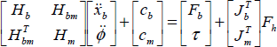
Where:


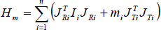
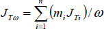


The symbols in the above equations are defined as followings:
The mass of link i of the space manipulator
The total mass of the whole space robot system
The position vector of centroid of the link i
The position vector of joint i
Unit vector indicating joint axis direction of the link i
The position vector of the total centroid of the space robot system
Inertia tensor of the link i with respect to its mass center
Velocity dependent non-linear term for the base
Velocity dependent non-linear term for the manipulator arm
The External force and torque on the space base
The external force and torque on the end-effector
The joint torque of the manipulator arm
The inertial matrix of the space base
The inertial matrix for the manipulator
The coupling inertial matrix between the space base and manipulator
All vectors are described with respect to the inertial coordinate system ΣI, Cb and Cm can be obtained by inverse dynamic. The inverse dynamic computation is useful for a computed torque control. Here, the authors use n-order recursive Newton-Euler approach [J. S. Y. Tuh, M. W. Walker and R. P. C. Paul (1980)] [K. Yoshida (1997)] to compute inverse dynamics. In addition, calculating inverse dynamics can obtain the reaction force/moment on the space base.
For assumed space robot model from Fig. 2, the Newton and Euler equation of link i can be expressed as following form:

where: Fi, Nt are inertial force and moment exterting on the centroid of link i. Otherwise we define force and moment fi, ni exterting on the joint, fci and nci exterting on the end-effector. Thus, the dynamic equilibrium expressed as following form for a revolution joint:
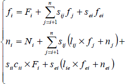
From the equation (17), we can obtain every joint torque as following:

Moreover, the reaction force and moment on the space base can be obtained as following equations:

The equation (19) can be used to measure the interaction between the space base and space manipulator. These parameters are very important reference for designing the attitude control system and orbit control system. Moreover, the coordinate control of space base and space manipulator needs these parameters. The symbols in equation (17), (18) and (19) are defined as followings:
the element of Incidence matrix s, the detailed definition sees mathematical graph theory.
the element of Incidence matrix Sej (j = 1,…, n), that represents a flag to indicate if link j is a terminal end-link.
vector from joint i to joint j, from Fig. 2, we know lij = Cij-Cii.
vector from the centroid of link i to joint j.
For whole space robot system, the external force or torque on the space base Fb, which can be generated by jet thrusters or reaction wheels, and Fe can be assumed zero before the end-effector contacts the objective. Therefore the linear and angular momenta of whole system are conservative when Fh= 0. The motion of system is governed by only inertial force/torque on the manipulator joint τ. Thus, we can obtain the following momenta equation from equation (3).

At the beginning, assume
Substituting equation (21) into equation (2), we get

where:
In this section, we describe to estimate the motion state and equation of USS. The USS to be rescued has unique characteristics as follows: the orbital information such as altitude and inclination of the USS will be known by the ground control station. The size, shape and mass property of the USS are also well known in advance from design phase information. The handle location will be identified by human decision. Therefore we also assume that the USS is equipped with visual marker, signal reflectors, GPS, and so on for simplification.
Here, we assume that the USS is nearly axis-symmetric shape with a grapple handle on the maximum momentum axis in order to simplify the complicated problem. Moreover, there are some mark points on the USS so that the CCD cameras equipped in manipulator end-effector can measure the position, orientation and estimate its spinning velocity. Hence, the grapple handle is the key point of tracking trajectory of space manipulator. Therefore, the mission of CCD cameras is to measure the position and orientation from manipulator end-effector coordinate ΣE to the coordinate frame ΣO attached to the USS. Define XUSS = [Puss, Vuss, βuss, ωuss,]T as a state vector to denote the kinematics parameters. So the motion equation of USS is given as following forms.

The symbols in the above equation are defined as followings:
Denotes a non-linear function which describe USS motion
Denotes white Gaussian system noise vector.
Puss = [x, y, z] be the position of the center of USS mass
Vuss = [vx, vy, Vz] be the velocity of the center of USS mass
βuss =[β1, β2, β3] be the orientation angles from coordinate frame ΣO to ΣE.
ωuss= [ωx, ωx, ωx] be the angular velocity of USS.
A 12th-order extended Kalman filter (EKF) [Hiroyuki Nagamatus, et al. (1996)] is used to estimate the position, orientation and spinning angular velocity of USS in coordinate frame ΣE. Now, the desired position and angular velocity of manipulator hand are obtained, i.e, the position and spinning velocity of USS.
In this section, we will address to plan a tracking trajectory according to the feature of the target. According to motion estimation of USS mentioned above, the key parameters of USS have been gotten from the sensors of space robots, which mainly include position and spinning velocity. Here, we also assume that the USS keeps slow spinning motion in free-floating situation, thus, the motion trajectory of grapple handle on the USS is a circle trajectory. Therefore, the mission of space manipulator is to track and approach towards the USS. The tracking trajectory must satisfy that the relative motion velocity between the USS and the space manipulator end-effector is close to zero in order to not cause the severe collision, this is the constraint of the trajectory planning.
Because the USS keeps the even circle motion, we plan a spiral ascending trajectory for space manipulator in Cartesian space. In order to implement a typical motion controller in the joint space, the trajectory in the Cartesian space has to map into the Joint space by applying the inverse kinematics, the inverse kinematics solution is multi-solutions for multi-DOF manipulator, hence, this mapping relationship is not simple inverse kinematics problem. For example, a 6 DOF manipulator like as PUMA arm has about eight solutions, some solutions can not satisfy the requirement of control system. Moreover, some solutions cause the dynamics singularities. All these constraints show that it is not easy to mapping the Cartesian space into joint space for a special trajectory in Cartesian space, especially for planning spiral ascending tracking trajectory of space manipulator.
Trajectory planning in Cartesian space
Because our research topic focuses on how to track and approach the USS, the task of manipulator is usually specified as sequences of Cartesian knot point through which the manipulator end-effector must pass. Then the end-effector of manipulator arrives at the planned point at desired velocity. Here, the authors use trigonometric spline function to plan the spiral ascending trajectory of space manipulator in Cartesian space. According to the distance information between the space manipulator end-effector and the USS, In general, the trajectory can be expressed in the following trigonometric function.

where: a, b and c are constants, x0, y0 and z0 are the initial position of the manipulator end-effector.
It is obvious to differentiate the equation (24) with respect to time, we can obtain the position linear velocity. Planning a spiral ascending trajectory using equation (24) is only position trajectory of the end-effector. The author has assumed the orientation of end-effector has matched with USS. Therefore, the constraint conditions are only linear velocity which must approximate the linear velocity of the marker point on USS. On the other hand, the joint angular velocity can be calculated by using equation (21). Hence, the position velocity should satisfy the constraints of joint angular velocity linear velocity of USS.
At the beginning, using forward kinematics calculates the position and orientation of end-effector at initial joint qinit =[q1, q2,…qn], n expresses the number of manipulator DOF. Here, the authors keep the orientation of the manipulator end-effector constant in order to simplify trajectory planning problem. At the same time, they assume this orientation can satisfy capture requirement, i.e. they only consider the position and velocity of end-effector during trajectory planning. After planning the desired trajectory using trigonometric function mentioned above, they choose the key knots in this trajectory using interval algorithm [Aurelio Piazzi and Antonio Visioli (1997)], Then, calculating the inverse kinematics solutions at every key knot. Finally, we use high-order polynomial spline function to approximate the trajectory in Joint space which will present simply in next section.
Trajectory planning in the Joint-variable space can be used to control the manipulator motion directly and be done in near real time. Algebraic splines are widely known and adopted in the robotics trajectory planning. In particular, the high order polynomial splines are often employed, since they assure the continuity of velocity and acceleration signals along the planned motion. Besides, the parameters are easy to calculate and large oscillations of the position function and its time derivatives are prevented. Suppose to have a initial joint position sequence qinit =[q1, q2,…qn] and the inverse kinematics solution at one key knots qknot = [q(k, 1), q(k, 2),…,q(kn)]. Between the initial joint qinit and one knot joint qknot, the general method uses following high order polynomial function to generate the joint trajectory:

This polynomial function represents the joint position at time ti, the coefficients of equation (25) can be determined by considering the following initial and final conditions:
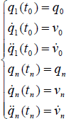
and for any knot point:
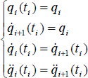
The equation (26) is constraint function in every interval [qinit, qknot], the equation (27) is the pontes of two segments of the trajectory at the key knot.
According to the constraint conditions presented in equation (26), the authors define a quintic polynomial to generate a sequence q at time interval t = [t0, t1,…,tn].
In section V, the authors addressed the method to plan a spiral ascending trajectory in Cartesian space and Joint space respectively, and map into joint space using interval algorithm. In this section, we utilize an illustrative example to demonstrate that this trajectory can be realized in real space manipulator, the space robot system has a six DOF manipulator and all joints are rotational joints. Moreover, the geometric structure is the same as PUMA robot in order to make the inverse kinematics solution easy. Here, we assume that each link of manipulator is cylindric. The radius of link r = 0.04m. The table I shows the dynamics parameters of the space manipulator system.
Parameters of space robot system

Parameters of space robot system
In the simulation study, the authors use the trigonometric spline function to plan the desired tracking trajectory in Cartesian space, then choosing the key knot points in this trajectory as the interval reference point using interval algorithm, they calculate and select the inverse kinematic solutions. Finally, they use the five order polynomial function to generate the trajectory in Joint space. According to desired angular value, angular velocity from joint trajectory generator, the authors use the Dynamic model of space manipulator as the control object design PD controller to control the joint. Here, the authors define the attitude control system of space robot is off in order to simplify the control.
The goal of simulation is to verify that the spiral ascending trajectory can be realized in Joint space. The authors also measure the coupling force and torque between the manipulator and space base in order to confirm whether the attitude and orbit control system can compensate the orientation and position disturbance of the space base. Fig. 3 shows the desired spiral ascending trajectory in Cartesian space. Fig. 4 and Fig. 5 show the position and orientation disturbance of the space base because of the motion of the space manipulator. The results always keep in a small bound so that these disturbances can be compensated by the attitude and orbit control system. Moreover, the orientation and position of the space base keep the formula movement. Fig. 6 shows the joint angular degree after inverse kinematics during operation. Fig. 7 shows the torque of the manipulator joint because of the motion of space manipulator. All simulation results can be used to verify that the tracking trajectory of space manipulator is easy to realize in fact.

Spiral ascending trajectory in Cartesian space

Position disturbance of space base
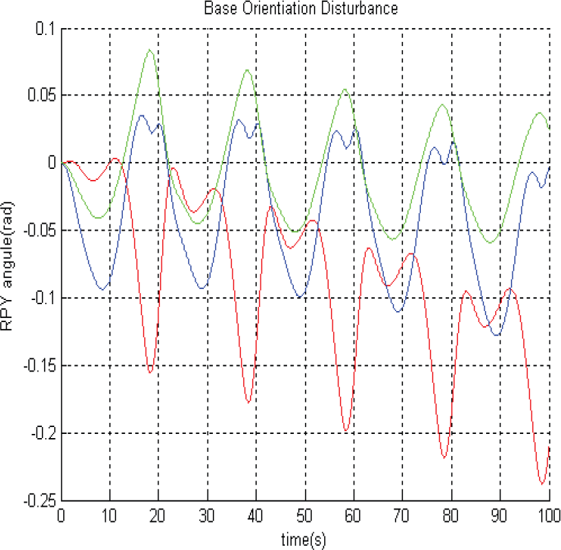
Orientation disturbance of space base

Joint angular degree after inverse kinematics
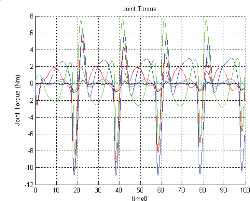
Joint torque of the space manipulator
This paper plans a spiral ascending trajectory of space manipulator for tracking and approaching the USS. One advantage of proposed trajectory is to change the relative motion mission to the fixture objective capture when the end-effector tracks the USS. The simulation study verifies that the proposed trajectory can be realized form engineering point of view.
Approaching and catching the uncontrolled satellite has become an important class of future space robotic mission. In this paper, the authors present the proposed tracking trajectory and preliminary work. In the next phase, we will focus on the following parts as our future work (1) optimizing this trajectory; (2) the contact and impact analysis during capturing process; (3) space robot motion stabilization after capturing the target satellite.