
Abstract
In this research, the authors have addressed the collaboration calibration and real-time three-dimensional (3D) localization problem in the multi-view system. The 3D localization method is proposed to fuse the two-dimensional image coordinates from multi-views and provide the 3D space location in real time. It is a fundamental solution to obtain the 3D location of the moving object in the research field of computer vision. Improved common perpendicular centroid algorithm is presented to reduce the side effect of the shadow detection and improve localization accuracy. The collaboration calibration is used to generate the intrinsic and extrinsic parameters of multi-view cameras synchronously. The experimental results show that the algorithm can complete accurate positioning in indoor multi-view monitoring and reduce the complexity.
Keywords
Introduction
The object tracking is a challenging task for various data sets; therefore, it is still a hot topic of research in computer vision. 1 –5 To extract the metric information from two-dimensional (2D) images, a flexible calibration technique is proposed. 6 In this technique, a planar pattern shown at least two different orientations is required. It is a fundamental theory and used in practice to locate the target. To the best of our knowledge, the three-dimensional (3D) localization algorithm for the multi-view system still needs further research. 7 –9
In disaster environment, dynamic localization is the key for mobile robot to carry out various rescue missions. The key areas are monitoring real-time 3D location of mobile robot and providing real situation of disaster scene for rescue crews. The current localization technology focuses on localization by single 3,5,10 or binocular vision, 6,11,12 and localization accuracy needs to be improved. The main problems can be summarized as follows. First, the collaboration of multi-views is only used for object detection and extraction. There is no efficient method to fuse data from multi-views to obtain 3D space location of targets. Second, the target is located at 2D ground plane by single view or 3D space by binocular vision. Multi-view informations are not fully participated in the localization algorithm. Last but not least, the shadow detection can damage the localization results. The shadow on the floor can cause the localization errors significantly.
The camera calibration is a key issue in the camera system. Many researches focus on the accuracy of the parameters and localization results. 6,13 –15 However, the collaboration calibration of multi-view cameras is convenient and efficient at the deployment phase of indoor surveillance. It can reduce the heavy work of multi-camera calibration in visual sensor networks. This article pays more attention on the collaboration calibration.
To optimize the deployment of multi-view cameras, the position and orientation of cameras are predetermined and well ordered. Assuming the cameras are calibrated by the initial placement, the collaborative target localization with fault tolerance is presented to solve the target localization problem. 16 To tolerate potential sensor faults, a voting mechanism is adopted and a threshold value needs to be specified, which is the key to the realization of the distributed solution. Analytical study is conducted to derive the lower and upper bounds for the threshold such that the probability of faulty sensors that negatively impacts the localization performance is less than a small value. Correspondence between multiple cameras is critical to get the panoramic view of the environment. A state-of-the-art method for people tracking is presented for the multi-views. 17 It is a simple and robust method based on principal axes of people. The positions of people can be localized in the partial occlusion scenarios.
The localization of mobile robots is the frontier field of wireless sensor networks (WSNs) in disaster relief system. 18,19 For the indoor network blind areas, an autonomous dynamic localization algorithm is proposed. 20 This method chooses neighbor beacon node and sets up grids with received signal strength indication for the distance measurement.
The 2D localization algorithm is popular in the pedestrians monitoring. 17,21,22 First, the correspondence between multi-view cameras is used to match the pairs of objects with the minimum distance of various cost functions. The pedestrians are extracted by object detection technique. Second, the data fusion from multi-view cameras is used to improve the tracking results in each view. The centroid of foot position is located within the common ground plane. Third, the 3D space location of the pedestrians is located by 2D localization algorithm, which suggests the height is 0 in the Z-axis of the ground plane. The shortcoming is obvious that the foot position must be as accurate as possible, because the side effect of the shadow detection can damage the localization results.
Camera networks (CNs) have been widespreadly employed in many real-world applications of numerous aspects of life, such as intelligent transportation, smart city, and building surveillance. 23 With the development of camera-based technologies, image-based localization may be employed in an indoor environment where the global position system signal is weak. 24 Localization of a robot relative to its environment using vision information (i.e. appearance-based localization) has received extensive attention over the past few decades from the robotic and computer vision communities. Vision-based robot positioning may involve two steps. The first step involves learning some properties of vision data (features) with respect to the spatial position where observation is made (so-called mapping). The second step is to find the best match for the new spatial position corresponding to the newly observed features (so-called matching). The mapping from these visual features to the domain of the associated spatial position is highly nonlinear and sensitive to the type of selected features. 25
The next generation of sensor node such as Lotus mote enables higher performance, low power consumption, higher storage/memory, and higher speed processing capability than the older generation, such as TelosB or MicaZ motes, Crossbow Technology, which facilitates multimedia data preprocessing and compression in wireless multimedia sensor networks (WMSNs). 26 Target localization is to estimate the location of a target in the world coordinate based on the visual information of camera nodes. Target localization in WMSNs faces great challenges. First, image processing is in general costly to implement in local nodes, because the capabilities of computing are limited in local nodes. 27 Second, the bandwidth resources are also restricted in WMSNs. Thus, there are constraints to transmit a huge amount of visual data generated by cameras to central node or a base station. Third, since the sensing capability of a camera is characterized by directional sensing, the location information of a target in the depth dimension is lost in an image. Fourth, due to the cost limitation, visual nodes in WMSNs are equipped with low-resolution optical sensors. Thus, the accuracy of filtering and extraction of target’s position relevant information cannot be guaranteed in local sensor level. Vision-based surveillance by multiple cameras receives considerable attentions, so visual surveillance by multiple cameras will enlarge the area and information from multiple views can be used to solve many problems. 28
In the indoor multi-view system, it is a challenging task to obtain the real-time 3D space location of the mobile robot by the predetermined and well-ordered multi-camera system. The main contributions of this article can be summarized as follows. First, for the sake of the real-time location of the mobile robot, a 3D localization is proposed to detect the moving object and obtain 3D space location by fusing the 2D image coordinates from multi-views. Second, improved common perpendicular centroid (ICPC) algorithm is introduced to provide the error correction mechanism for the side effect of shadow detection and improve the accurate localization in the indoor intelligent monitoring. Third, the collaboration calibration of multi-view cameras is used to improve the efficiency of the deployment of indoor surveillance. Experimental results show that the proposed method can realize real-time 3D localization reliably and efficiently.
System descriptions
Figure 1 shows the flowchart of 3D localization in multi-view system. The final purpose of this work is to realize the real-time 3D localization. Therefore, camera calibration must be fulfilled, and the 3D space location of mobile robot is determined by the data fusion of 2D image coordinates from multi-views.
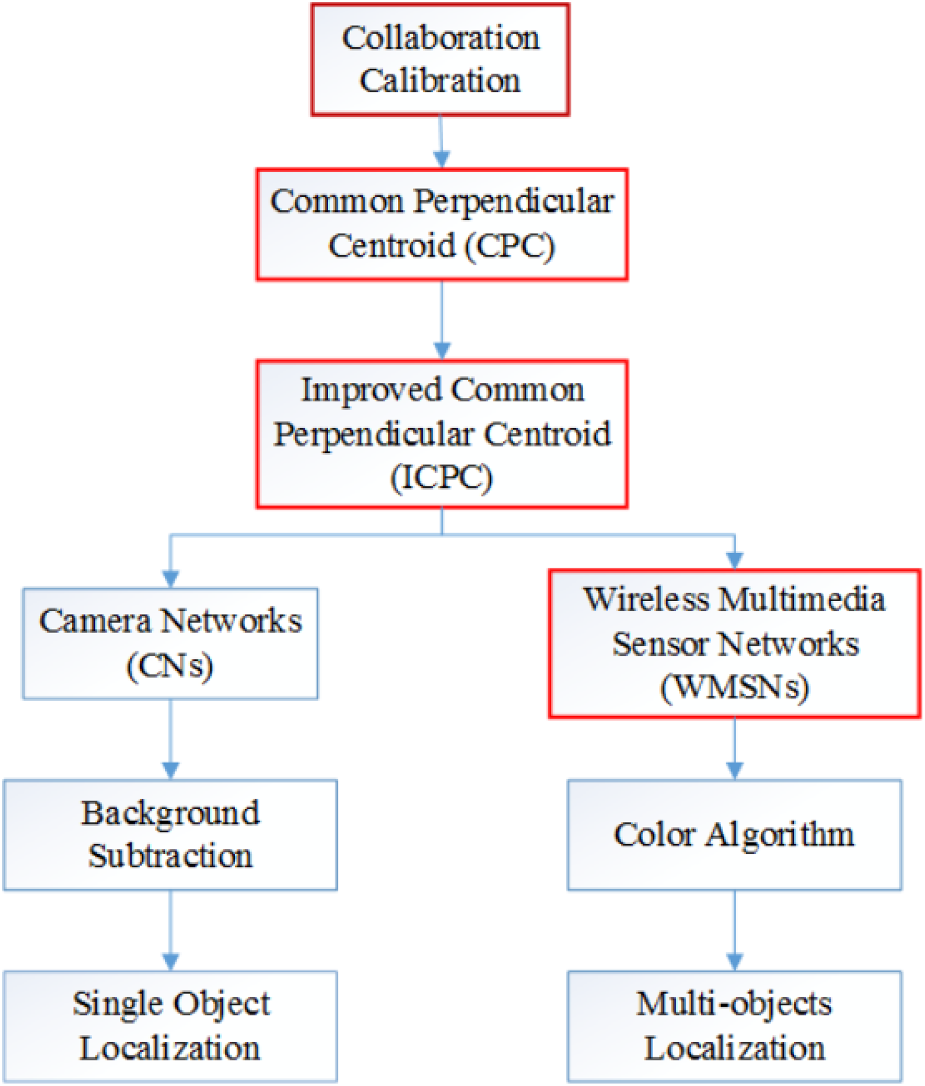
The flowchart of 3D localization in multi-view system. 3D: three-dimensional.
Collaboration calibration is to find out the intrinsic and extrinsic parameters of multi-view cameras by the coordinates of the reference points. The coordinates of the reference points can be divided into the 3D world coordinates and 2D image coordinates. The image coordinate is obtained by Harris corner detection. The position of the calibration board must be predetermined and measured to obtain the 3D world coordinates of the corner points.
CPC algorithm is the proposed 3D localization solution. It can take advantages of multi-view cameras and determine the real-time 3D space locations. ICPC algorithm is an improved version of CPC algorithm. Since the estimated 3D locations are always lower than the ground truths of the object, a base plane is employed by ICPC algorithm to slightly move up the estimated locations.
CNs have been widespreadly employed in many real-world applications of numerous aspects of life, such as intelligent transportation, smart city, and building surveillance. 23 The first experimental platform in this work deploys four charge coupled device (CCD) cameras to monitor the overlapping field of view in the interest of area. It is suitable for the proposed 3D localization algorithms to realize the data fusion from multi-views. The next generation of sensor node such as Lotus mote and PIXY enables higher performance and higher speed processing capability than the older generation, such as TelosB or MicaZ motes, which facilitates multimedia data preprocessing and compression in WMSNs. 26,29 The second experimental platform in this work deploys four PIXY visual sensors in the room and localizes the mobile robots by the proposed algorithms. WSNs are employed for the data transmission. 20
To obtain the 2D image coordinates from multi-views, background subtraction is used for object detection in the CNs platform. It is capable to track the single object in indoor environment. 30 Since the lights and illuminations changes can cause high false alarms rates, it is not employed for multi-object tracking. PIXY visual sensor is the latest product in the robotics field. 26 It employs the color algorithm to distinguish between different colors in the real world. Since the color algorithm provides very low false alarms rates, it is used for multi-object tracking by the proposed 3D localization algorithm. The red boxes in Figure 1 show the main contributions of this work.
Harris corner detection and extraction
For the issue of the corner point detection, the technology of Harris corner is employed. Due to the image edge effect and adjacent corner point phenomenon, an improved Harris algorithm is presented to detect and extract the image coordinate. It can handle the effect of the image edge and double-peak phenomenon efficiently.
Image edge effects processing
The matrix obtained by corner response function (CRF) covers all the characteristics of the gray variance of the image. Among them, the location of the corner point is relatively complex. At first, the method adopts 5 × 5 search window, with the pace of 1 pixel to traverse the entire image, to look for the local maximum in small scale. And then through a fixed threshold, the position of the corner point is localized. The formula is as follows

where row and col are the length and width of the image,
Search results of the local maximum matrix in small scale are shown in Figure 2. Before repair, detected corner points with the red cross mark are away from image edge because there are many 0’s in the edge area of the matrix.
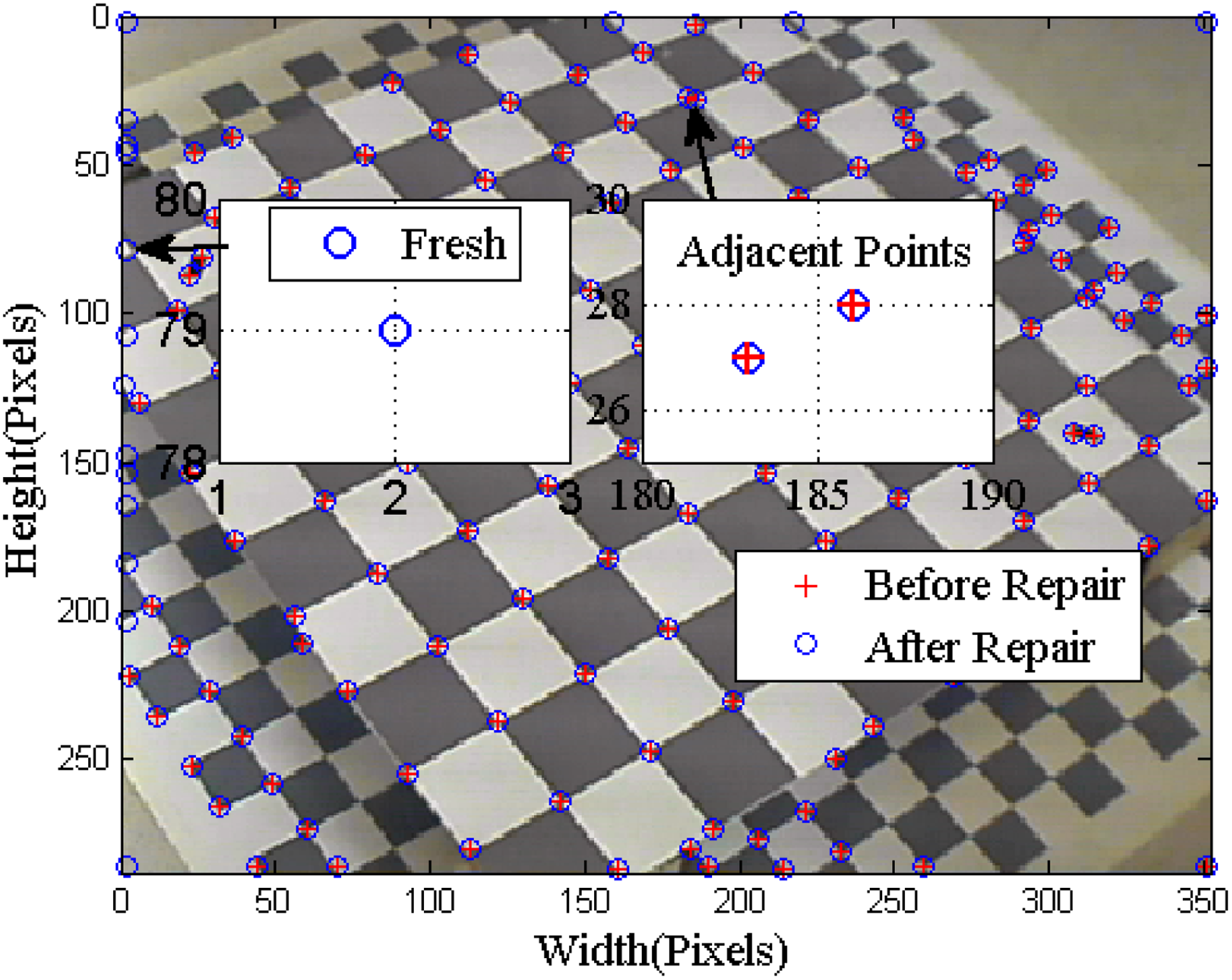
The small-scale peak search.
Therefore, the method focuses on the data repair of the matrix edge, and the adjacent coverage principle was presented. The first and second rows of CRF matrix are replaced with the data of the corresponding unit in the third row. Other edges have the similar application. After repair, the fresh corner points with blue circle mark are shown in the amplification region above; when CRF data are greater than a certain threshold, the corner points can be extracted.
Center point principle of adjacent points
In the acquired images, the double-peak phenomenon is depicted clearly as shown in Figure 2, the amplification area of adjacent points. The image distance between adjacent points is less than 5 pixels. Since the distance of world coordinates between the feature points in the calibration board is about 10 cm, the image distance between the feature points is greater than 5 pixels.
To eliminate the adjacent points, a threshold to judge the distance between adjacent points is present. If less than the threshold, the center point is computed, that is,
Extraction of the effective corner points
In the experiment environment, the corner points around the calibration board need to be filtered out automatically. According to the position feature of corner points in the calibration board, the slope formula between two points is used. All the corner points, whose slope is greater than a certain threshold, are eliminated, and then the corner points of the calibration board are retained. First, 2 × 9 corner points of both sides in the calibration board are selected manually. Second, the slope with the each pair of the points on both sides is calculated. Third, the corner points of the calibration board are determined through the comparison between the slope and a fixed threshold. To prevent the edge effect, the 9 × 9 corner points inside the calibration board are selected.
Collaboration calibration
The imaging model is a key link in the conversion process of image coordinates and world coordinates. 6 This work adopts four cameras with an angle of 40°, which is applicable to the pinhole imaging principle. Therefore, the linear model can be used for coordinate transformation.
Linear model
To estimate the 3D camera motion from 2D images, vision techniques are usually based on the pinhole camera model described in Figure 3, where

Frame definition.
The linear model between the coordinates of a physical 3D point

where s is a scale factor,

Homogeneous coordinates simplify the notation needed to describe perspective projections and allow for projective-geometric concepts such as points and lines at infinity. 33
Linear model of collaboration calibration
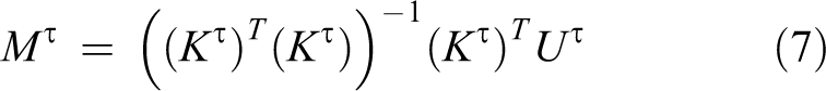
If the projection matrix is

where

Assuming

where
Nonsingular deployment of calibration boards
The characteristics of the linear model are the invariance of the translation and rotation. It causes that Kτ
matrix is unable to achieve the full rank, which is expressed as
However, when the calibration board is deployed in different heights, the third and seventh columns of matrix Kτ
fuse two groups of data, which leads to a linearly independent feature. That is
Aiming at the linear correlation feature of matrix Kτ , the calibration boards are placed separately in the height of 27 and 130 mm from the ground level horizontally.
Since the angles and orientations of four cameras are predetermined, they have the common ground plane of the monitoring area. In the calibration stage, the cameras can snapshot and extract the feature points of the same calibration board. Therefore, the accomplishment of the calibration algorithm for four cameras can be achieved synchronously—that is the presented collaboration calibration method.
3D localization based on ICPC
The 3D localization was implemented in the indoor environment. The robot does not need to carry any wireless sensor to realize the indoor localization. The image coordinate of the target is extracted by the foreground segmentation of the predetermined multi-view cameras. And then ICPC is used for real-time 3D localization in the world coordinate system.
Adaptive background mixture model
The mathematical model of the background subtraction is adopted to detect the mobile robot. First, three Gaussian models are established to describe the background model and foreground model. Second, the first 40 frames are used to train the background model. Third, the threshold of the background model is set to 0.7. It is robust to the most noises in the indoor environment.
To train the background model, 40 frames without foreground objects are used to build the model. Then, the background model is updated by the incoming frames. At any moment N, the mathematical models of the pixel XN are as follows

where wj
is the weight value of the jth Gaussian model and
The computational complexity is
The positioning result of the mask image by adaptive background mixture model (ABMM) is shown in Figure 4(a). And the smallest rectangle method is used to localize the white region. Finally, the localization result is shown in Figure 4(b).

The localization method of ABMM. (a) Mask result and (b) localization result. ABMM: adaptive background mixture model.
Common perpendicular centroid
The 2D image coordinate of the detected target in each view of the monitoring cameras is the most important evidence to localize the mobile robot. The experimental platform of this article is shown in Figure 5, and the straight line between the 2D image coordinate and the mobile robot is the specific ray of one view through the optical centerof the camera. Because of the environmental noise, 6,16 two rays shown as the dotted lines cannot be intersected at the same point. The bold solid line is the common perpendicular between two dotted lines in 3D space. The red cross mark is the center point. Any two rays in the experimental platform can find out the center point of the common perpendicular. The centroid of all center points is the estimated 3D location of the robot.

The center point of common perpendicular.
The ray equations from two cameras to the robot are shown as follows


where
Assuming the direction vector of line
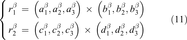
Assuming the intersection point between line

Therefore, the direction vector of the common perpendicular for line

Assuming

The parametric form of line

Line
Therefore, the center point of the common perpendicular and the estimated coordinate of the robot are as follows

Improved common perpendicular centroid
The main challenge of the background model is the shadow on the floor caused by the robot moving. It can cause the significant errors between the detected bounding box by ABMM and actual bounding box of the mobile robot. Figure 6 depicts the errors in details. The yellow bounding box in Figure 6(a) is generated by ABMM. The green bounding box is the actual size of the robot. It clearly indicates the size fluctuation caused by the shadow on the floor. The consequence is that there is a standard deviation between the estimated and actual position of the mobile robot. Figure 6(b) describes the situation. The red plus is the estimated position of the robot and the blue circle is the actual location obtained by the centroids of the bounding boxes. The distance between the two positions is the standard deviation. Since the shadow on the floor has a great impact on the detection results, the estimated position is lower than the actual position in the majority of cases. The error correction is the motivation of ICPC algorithm.

The standard deviation of ABMM. Standard deviation of the (a) bounding boxes and (b) centroids. ABMM: adaptive background mixture model.
The solution of the error correction is presented by ICPC algorithm. First, the six center points are generated by CPC algorithm in the “Common perpendicular centroid” section. They are distributed in the 3D space according to the four rays obtained by the four views. The four blue balls and two green balls represent the six center points. Second, the centroid of the six center points is located, which is represented by the red balls in Figure 7. The base plane is generated based on the centroid location horizontally. Third, the six center points are divided into two groups by the base plane. The four blue balls are lower than the base plane and two green balls are higher than the base plane. Last but not least, only the red ball and two green balls are used by ICPC algorithm. Among them, the red ball is the centroid of the six center points and the two green balls are higher than the base plane. Then, the centroid of the three balls is the estimated position of ICPC algorithm.

The demonstration of ICPC algorithm. ICPC: improved common perpendicular centroid.
After experimental confirmation, the estimated position of CPC algorithm is always below the ground truth of the robot. Therefore, a reference point is presented—it is the estimated position of CPC algorithm. The center points of common perpendiculars, above the horizontal plane of the reference point, are screened out, and the centroids are refined as follows

where
ICPC algorithm is a data fusion method to obtain the 2D image coordinates from multi-view cameras and presents the estimated 3D space location of mobile robot. There are two phases of data fusion of ICPC algorithm. The first phase of the data fusion method is CPC algorithm. The multi-view system in indoor environment has four side-view cameras in this work. When mobile robot is moving in the monitoring area, each side-view camera can locate the detected bounding box of mobile robot in its own image coordinate system by background subtraction method. Thus, a ray is generated from the optical center to the centroid of detect bounding box for each side view. Four side-view cameras can present four rays from its optical center to the mobile robot. Four rays can be divided into six unique pairs of rays based on the mathematical model
The second phase of the data fusion method is the error correction of ICPC algorithm. Since the shadow detection can cause the significant errors between the detected bounding box and actual bounding box of mobile robot, there is a standard deviation between the estimated and actual position of mobile robot. As shown in Figure 5(b), the estimated position is lower than the ground truth of mobile robot in the majority of cases. The error correction mechanism of ICPC algorithm is to filter out the 3D space locations below the base plane. Figure 6 depicts that four blue balls below the base plane are filtered out. Only the centroid of the six locations and the locations above the base plane are used for the data fusion method of ICPC algorithm. As shown in Figure 6, the red ball and two green balls are used for data fusion. The centroid of the locations above the base plane is the data fusion method to present the estimated 3D space location of mobile robot by ICPC algorithm. The black ball in Figure 6 indicates the situation. The data fusion method can gurantee that the estimated 3D space location of ICPC algorithm is always higher than the estimated 3D space location of CPC algorithm. Thus, the standard deviation caused by shadow detection can be compensated by the error correction mechanism of ICPC algorithm.
ICPC algorithm is a parameter-free method 34 –36 that automatically computes the estimated 3D space location of mobile robot. However, when the location geometry is not desirable, the constrained weighted algorithm avoids the ill-conditioning problem efficiently. 37 The relationship between the source position and the auxiliary variables is explicitly incorporating in order to overcome the problems such as the accurate sensor location information may not be avaible. In this work, four side-view cameras present six locations of mobile robot. Since the cameras are deployed manually and calibrated by Harris corner technology, their locations and extrinsic parameters may not be accurate. The prior knowledge of a weighting matrix is helpful to compensate the errors caused by sensor position uncertainty. Because of the dynamic changes of illumination and environment noises over time, it is very difficult to obtain the prior knowledge of the weighting matrix over time. Thus, ICPC algorithm automatically determines the centroid of the six locations of CPC algorithm as the estimated location of mobile robot. There is no prior knowledge of the weighting matrix and no need to tune the parameters manually. It can achieve a good balance between model complexity and localization accuracy.
3D localization in WMSNs
The smart devices architecture of WMSN is a mesh network, including PIXY sensors, Arduino UNO, XBee S2, and PC. The image-processing task is completed by PIXY. The processing results include image coordinates and bounding boxes of detected mobile robot. In addition, XBee sensor network is responsible for data transmission, and the coordinator is used for data aggregation from multi-views of visual sensors synchronously.
Mesh network
The mesh network of the proposed WMSNs is shown in Figure 8. The predetermined four visual sensors are located at the four corners of the room. The red star is the coordinate origin and the ground plane coordinates of the visual sensors are measured in millimeter. All visual sensors are directed to the center of the room. About 1.5 × 1.5 m2 area of the room is overlapped by four visual sensors, and the rest of the room is overlapped by less than four visual sensors. The mobile robot is carrying the PC that connected with the coordinator and moving at the center of the rooms. The visual sensors record the target with the interval of 1 s synchronously, and transmit the predefined package to the coordinator in its own time slot asynchronously. In addition, the state of the visual sensor is shifted from sleep mode to active mode as the mobile robot is detected. If the mobile robot is not detected by any visual sensors, the dynamic localization of the mobile robot in WSN will provide the navigation service. 20,38

The mesh network of the proposed WMSN. WMSN: wireless multimedia sensor network.
Target detection
In fact, it is difficult to detect potential targets with low false alarms rates. In addition, the methods need to be implemented by smart devices with limited hardware resources like PIXY. Thus, color algorithm, which tracks the color blobs by hue saturation value color space, is adopted by PIXY to detect single color information.
29,39
–41
The 2D image coordinates and bounding boxes are transmitted to Arduino UNO. The detected results are shown in Figure 9. The cooked image in Figure 9(a) shows the red helmet fixed at the tripod on the mobile robot. Because of the rotation and shape invariance, the color information on the helmet is discriminative to other objects. Further, its height is greater than most of obstacles in the rooms. In addition, the color information can be detected successfully, when the mobile robot is still in the same place or moving around. The bounding box in Figure 9(b) describes the centroid and size of the helmet. The minimum block of the bounding box is 200 pixels. Therefore, most of the false alarms can be filtered out. The signature

The detected mobile robot by the color algorithm. (a) Cooked image and (b) bounding box.
The differences between the 3D camera and 2D cameras can be concluded into four aspects. First, the cost of 3D cameras is more expensive than that of the off-the-shelf 2D cameras. 39 It is much easier and less expensive to deploy the 2D cameras in the large-scale area. Second, 2D CNs have been widespreadly employed in many real-world applications of numerous aspects of life, such as intelligent transportation, smart city, building surveillance, and crime prevention. 23 Third, the computer vision techniques in 2D CNs are matural technology in the real life, which are capable of intelligent processing using multiple cameras, such as target detection, localization, identification, tracking, and events of interest, for public security. For example, the 2D cameras in an airport environment can implement the face recognition and tracking algorithms for the passengers at important locations of interest. 42 The next generation of sensor node such as Lotus mote enables higher performance, low power consumption, higher storage/memory, and higher speed processing capability than the older generation, such as TelosB or MicaZ motes, which facilitates multimedia data preprocessing and compression in WMSNs. 26,29 WMSN are an important and exciting new technology with great protential for strengthening the traditional WSN applications, as well as creating a series of new multimedia applications such as multi-camera surveillance, visual target tracking, location-based multimedia services, and situation awareness. 40,41,43 Currently, 3D cameras have not been employed in WMSNs successfully.
Experiment and analysis
Experimental platform in CNs
The position and orientation of four CCD cameras are predefined and well ordered in the indoor environment. The focal length and photosensitive area of the cameras are 8 mm and 1/3, respectively. The video capture card is the model of 9508AV with the video compression algorithm H.264. The frame rate and resolution of the video are 25 fps and
The fundamental task is the collaboration calibration. First, the calibration board is placed horizontally at the center of the monitoring area and shot by the predetermined four cameras. The heights of the calibration board are 27 and 130 cm in order to overcome the nonsingular of the projection matrix

The corner points of the 27-cm height calibration board. (a) First view, (b) second view, (c) third view, and (d) fourth view.

The corner points of the 130-cm height calibration board. (a) First view, (b) second view, (c) third view, and (d) fourth view.
Figure 12 depicts the localization results of CPC algorithm. The estimated 3D space location of any corner point of calibration board is located by four detected corner points of four side-view images in Figures 10 and 11. It is the centroid of six 3D space locations by CPC algorithm. The estimated locations are close to the ground truth of corner points. The shapes of the matrix formed by the estimated locations are the same as regular squares. However, because of lens distortion, the localization accuracy at the center is better than that at the edge of the monitoring area. Even in the worst cases, the estimated 3D space locations represented by the red plus markers are around the ground truths of corner points of calibration board represented by the blue circles obviously.
The localization of CPC algorithm of calibration boards.
Figure 13 describes the localization errors of CPC algorithm. Since the calibration board has obvious feature points, the side effects of the illumination change can be limited to minimum. The estimate location of the detected corner points can be as accurate as possible. The majority of the localization errors are around 2 mm. All the errors are less than 7 mm eventually. The curve shows regular fluctuation. Some of the locations have a violent fluctuation and the rest of the locations are relatively stable. It is due to lens distortion and has a significant impact on the localization accuracy at the edge of the side-view images. However, the overall localization errors are controlled within a reasonable range.

The localization errors of corner points.
Figure 14 depicts the cumulative distribution of the localization errors of CPC algorithm. Over 90% of the errors are less than 4 mm. Around 10% of the errors are less than 1 mm indeed. It indicates that CPC algorithm has a good performance for the localization of the 3D space points. Since the calibration board has distinct feature points and there are no side effects of shadow detection, the 3D space points can be accurately located by Harris corner detection technology. CPC algorithm can precisely localize the corner points based on the detected corner points of four side-view images. It is an ideal localization accuracy in the most applications.

The cumulative distribution of the localization errors.
The experimental environment has the characteristics of the majority of robot application scenarios in the indoor lab. It is situated in a densely populated area, and the light source is complex including the sunlight and daylight lamp. Figure 15 describes the detection results from four side views in the real time. Each column presents a side view of the monitoring area. Each set of two rows forms a group of real-time detection results and masks in a sampling time. Figure 15 clearly indicates that the majority of the errors are generated by the shadow on the floor. The error correction can be obtained by ICPC algorithm. The yellow bounding boxes are the detected results of mobile robot by background subtraction. There are obvious tails at the foot of mobile robot. The centroids of the bounding boxes significantly deviate from the ground truths of mobile robot. The positions of the centroids are lower than the positions of the ground truths. Since the 2D image coordinates of the detected results from four side-view images are eventually lower than the actual image coordinates of mobile robot, the estimated 3D space locations of CPC algorithm are lower than the ground truths of mobile robot accordingly. It is crucial to compensate the errors caused by the shadow on the floor. The error correction mechanism of ICPC algorithm is used to minimize the side effects of shadow detection.

The detection results and masks of four side views. (a) First view, (b) second view, (c) third view, (d) fourth view, (e) first view, (f) second view, (g) third view, (h) fourth view, (i) first view, (j) second view, (k) third view, (l) fourth view, (m) first view, (n) second view, (o) third view, (p) fourth view, (q) first view, (r) second view, (s) third view, (t) fourth view, (u) first view, (v) second view, (w) third view, and (x) fourth view.
In the “Adaptive background mixture model” section, ABMM is presented to detect the 2D image coordinate of the mobile robot in the area of interest. In the “Common perpendicular centroid” section, CPC is proposed to provide the methodology to fuse the 2D image coordinates from multi-views to acquire the 3D space location of the mobile robot. Then, centroid ABMM CPC (CACPC) is to localize the 3D location of the centroid of the robot in the world coordinate system. To improve localization accuracy and overcome the errors in 3D space, ICPC is proposed to reduce the side effects in the “Improved common perpendicular centroid” section. Further, centroid AICPC (CAICPC) method is presented to localize the real-time location of the centroid of the mobile robot.
For comparison with other related works, the principal axis-based tracking (PAT) algorithm 17 is used at the experimental platform. It is a state-of-the-art method for people tracking in computer vision. Since the proposed experiment has the similar scenario with the study by Hu et al., 17 PAT algorithm can be implemented in this platform. Because of the geometric symmetry of the robot in this experiment, the bottom point of the bounding box can be treated as the intersections in one view for a robot. The centroid of these intersections is selected as the ground point of the robot.
The positioning errors are shown in Figure 16. The localization errors of CACPC and CAICPC algorithms are relatively less than the other. By calculating the mean error, the best accuracy is 44.66 mm achieved by the proposed CAICPC. Some of the localization errors of CAICPC algorithm are less than 10 mm. It clearly indicates that CAICPC method has improved the localization accuracy of CACPC method at the every sampling point. Since CAICPC algorithm can compensate the errors caused by shadow detection, the estimated 3D space locations of CAICPC algorithm are higher than those of CACPC algorithm, and the localization errors of CAICPC algorithm are less than those of CACPC algorithm accordingly. Therefore, the overall mean error has around 1 cm improvement. Because PAT algorithm cannot effectively overcome the side effects of shadow detection, the positioning errors are greater than the others. The performance of PAT is not competitive with any proposed methods.

The errors distribution of the localization algorithms.
The error accumulation distribution of the localization algorithms is shown in Figure 17. The localization errors of CACPC and CAICPC algorithms can be limited within 10 cm. It indicates that the centroid part of the robot is more robust than the foot part of the robot. The localization results of the foot part of robot are worst because the side effects of shadow detection are serious at the experimental environment. The accurate positioning is achieved by the proposed CAICPC algorithm. It can successfully overcome the side effects of shadow detection and provide the real-time 3D space locations of mobile robot. The errors of the other algorithms are relatively greater. The worst results come from PAT, which is far behind the others.

The cumulative distribution of the localization algorithms.
Experimental platform in WMSNs
As shown in Figure 8, the proposed smart devices architecture of WMSNs is implemented on the self-developed platform. PIXY has 24 clock cycles per pixel
The synchronization message is transmitted to each visual sensor by the coordinator with the interval of 5 s. The key frame is recorded synchronously by the visual sensors with the interval of 500 ms. Further, two key frames are capsulated into the delivery package, and transmitted to the coordinator at its own time slot with the interval of 1 s asynchronously. The real-time data are clustered into discriminative groups by rules of spatial and temporal correlations.
The predetermined four visual sensors are placed at the four corners of the room. The angles of cameras are predefined. Thus, the two calibration planes are displayed at the centers of multi-views. Figure 18 shows the detected corner points of the low plane with the height of 1630 mm. They clearly indicate that the

The corner points of the 1630-cm height calibration board. (a) First view, (b) second view, (c) third view, and (d) fourth view.

The corner points of the 1732 cm height calibration board. (a) First view, (b) second view, (c) third view, and (d) fourth view.
The angles and orientations of the four cameras are predetermined and well ordered in the indoor environment. The angles and orientations are measured by the two calibration boards. Figures 10, 11, 18, and 19 show the effects of the snapshots of four cameras in two platforms. Since the proposed 3D localization algorithms demand the object tracking across multiple cameras with overlapping view, the overlapping field of view should be as big as possible. Thus, the calibration boards are employed as a tool to measure the angles and orientations of the four cameras. In the CNs platform, the calibration boards have
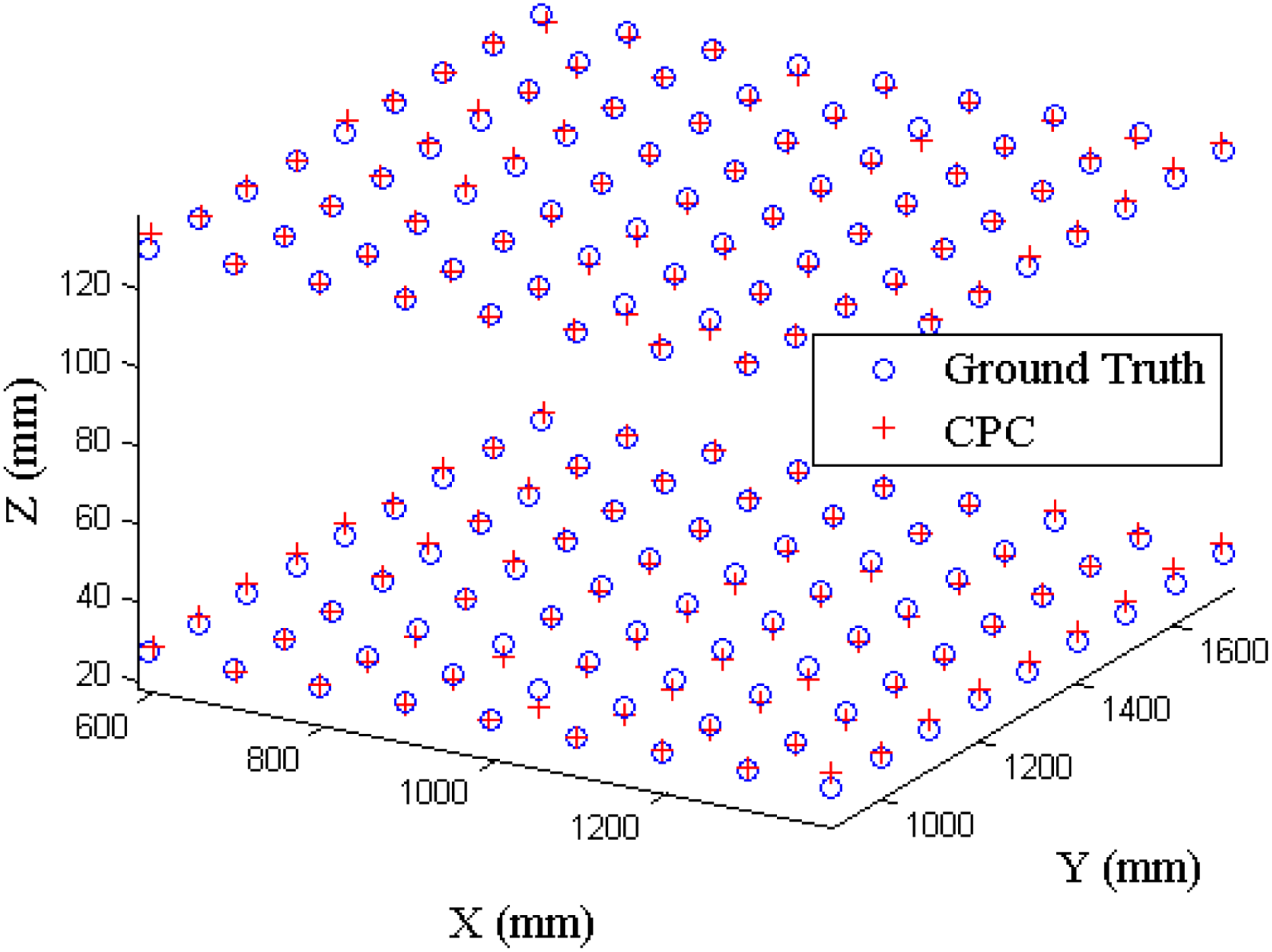
Figure 20 depicts the localization results of CPC algorithm. The estimated 3D space location of any corner point of calibration board is located by four detected corner points of four side-view images in Figures 18 or 19. It is the centroid of six 3D space locations by CPC algorithm. The estimated locations are close to the ground truth of corner points. The shapes of the matrix formed by the estimated locations are the same as regular squares. However, because of lens distortion, the localization accuracy at the center is better than that at the edge of the monitoring area. Even in the worst cases, the estimated 3D space locations represented by the red plus markers are around the ground truths of corner points of calibration board represented by the blue circles obviously.

The localization of CPC algorithm of calibration boards.
Figure 21 describes the localization errors of CPC algorithm. Since the calibration board has obvious feature points, the side effects of the illumination change can be limited to minimum. The estimate location of the detected corner points can be as accurate as possible. The majority of the localization errors are around 5 mm. All the errors are less than 11 mm eventually. The curve shows regular fluctuation. Some of the locations have a violent fluctuation and the rest of the locations are relatively stable. It is due to lens distortion and has a significant impact on the localization accuracy at the edge of the side-view images. However, the overall localization errors are controlled within a reasonable range.

The localization errors of corner points.
Figure 22 depicts the cumulative distribution of the localization errors of CPC algorithm. Over 90% of the errors are less than 7 mm. Around 10% of the errors are less than 2 mm indeed. It indicates that CPC algorithm has a good performance for the localization of the 3D space points. Since the calibration board has distinct feature points and there are no side effects of shadow detection, the 3D space points can be accurately located by Harris corner detection technology. CPC algorithm can precisely localize the corner points based on the detected corner points of four side-view images. It is an ideal localization accuracy in the most applications.

The cumulative distribution of the localization errors.
Since the size of 3D space in the WMSNs platform is 3.6 × 4.5 × 2.5 m3, the size of 3D space in the CNs platform is 2.2 × 2.5 × 1.8 m3, the monitoring area in the WMSNs platform is much larger than that in the CNs platform; thus, the localization errors are reasonably bigger. The maximum errors in WMSNs are around 11 mm and the maximum errors in CNs are around 7 mm. The lights and illuminations are also different in two platforms. Since the lights and illuminations are the major sources of the environmental noises, they can affect the detection results in computer vision techniques. In these experiments, CPC algorithm shows excellent localization performance. Even in the bigger monitoring area, CPC algorithm can control the average errors in 5 mm. There are no serious errors in the whole process.
Triangulation is important in various engineering applications, for example, surveying, navigation, metrology, astrometry, binocular vision, and target tracking, and is the fundamental estimation problem. Triangulation algorithm (TA) 31 is a conventional 3D localization method and used for the comparation and performance evaluation with the proposed algorithms.
Figure 23 shows 3D localization results of the mobile robot of circle trajectory in the room. The estimated 3D locations of CPC and ICPC algorithms are consistent with the trends of circle trajectory, respectively. However, since the false alarms at the target detection have significant impacts on the data fusion of CPC and ICPC algorithms, there are still a few of 3D locations far away from the circle trajectory. The estimated locations are slightly lower than the ground truths in the whole process, it is the common phenomenon in the 3D localization, since the object is always viewed by the cameras mounted on the top ceiling. 3D localization algorithms cannot determine the exact height of the object, even though ICPC algorithm can use the base plane in Figure 7 to make the estimated locations higher than that of CPC algorithm.
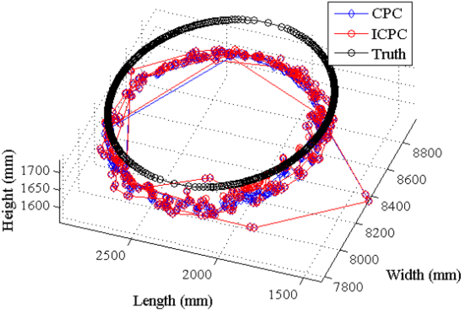
3D localization of circle trajectory. 3D: three-dimensional.
Figure 24 shows the cumulative distribution of localization errors for the performance evaluation of localization algorithms. All the errors of the proposed CPC and ICPC algorithms are less than 100 mm. Since only 85% of the errors of TA algorithm are less than 100 mm, the localization accuracy of the proposed algorithms is much better than the state-of-the-art method. Further, the maximum values of the errors of TA algorithm are more than 500 mm. It indicates that TA algorithm cannot provide the smooth localization results, unexpectedly. The average value of the errors of the proposed ICPC algorithm is 89.3281 mm. It is the best accuracy among the other localization algorithms. The localization accuracy of CPC algorithm is slightly worse than that of ICPC algorithm, since the estimated heights of ICPC algorithm are slightly higher than CPC algorithm.

The cumulative distribution of the localization errors of single object.
Figure 25 depicts the localization errors of localization algorithms. The trends of the proposed CPC and ICPC algorithms are smooth and stable. The magnitudes of the errors of TA algorithm are very big. It indicates that TA algorithm cannot provide stable localization results, especially at the beginning, the localization performance of TA algorithm is very poor due to the lights and illuminations changes.

The localization errors of single object.
Figure 26 describes the packet transmission of wireless communication in WMSNs. Because of the instability and package loss of wireless communication, only 24 samplings contain the synchronous detected 2D coordinates from four visual sensors. There are 176 samplings containing the synchronous data from three visual sensors with a missing view. Two-hunderd and thirty-six samplings only contain the synchronous data from two visual sensors with two missing views. Since the bottleneck at the coordinator, some of the transmission packages are missing accordingly. 20 It can seriously affect the localization accuracy of the proposed CPC and ICPC algorithms, since the proposed algorithms require the detection results from multi-views synchronously. If the received detection results are only from two views, there is only one center point instead of six center points in Figure 7, it will make the estimated location seriously deviated from the ground truth unexpectedly.
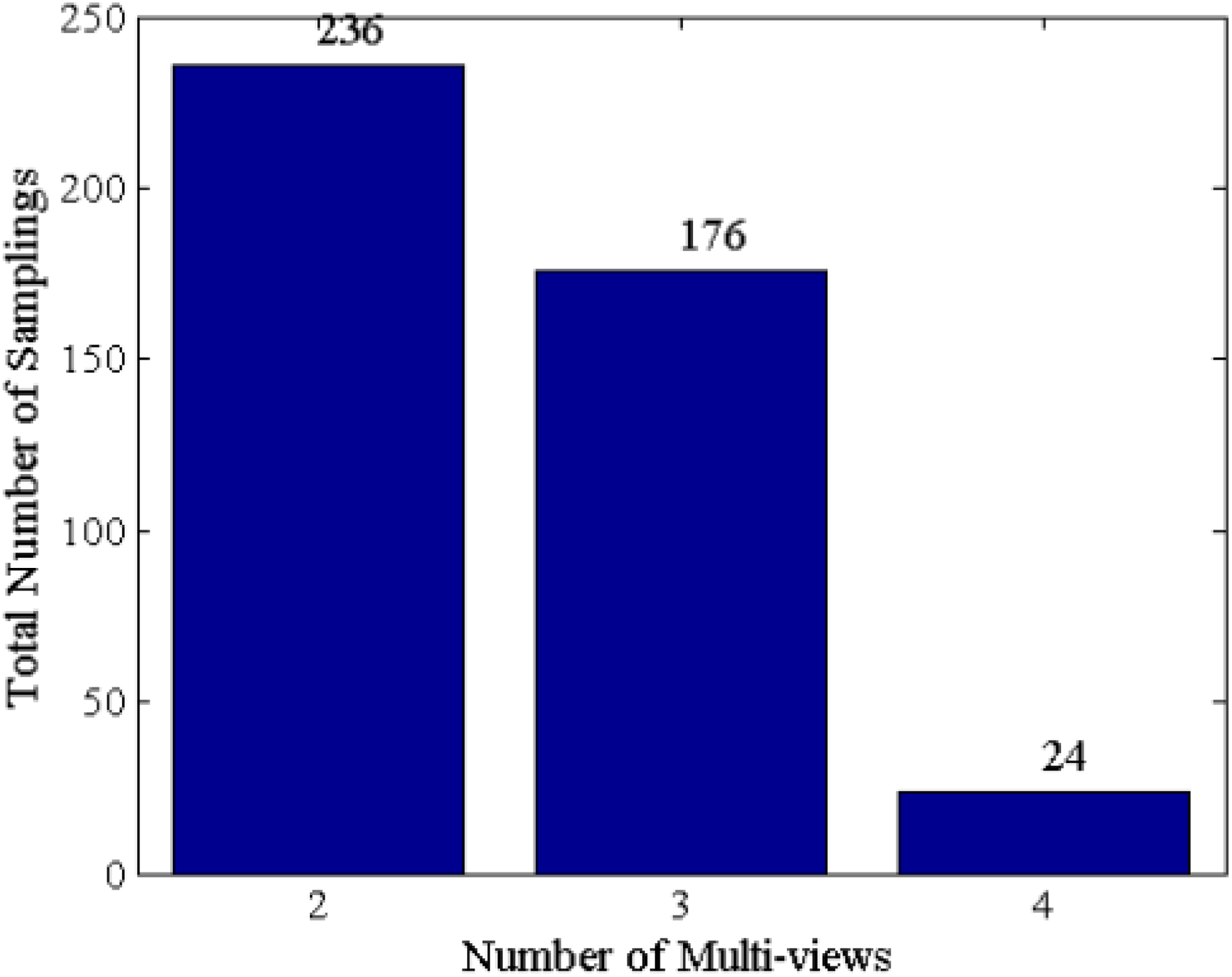
The wireless transmission in WMSNs. WMSN: wireless multimedia sensor network.
Figure 27 shows the multi-object detections from multi-views by the color algorithm. There are two mobile robots moving in the room, which have red and blue helmets fixed at the tripod on the mobile robots. The color algorithm builds the red and blue color models based on the color appearance of the helmets. PIXY visual sensor can build hundreds of color models based on the differences of color appearances. It means PIXY visual sensor can track hundreds of objects based on the differences of the color appearances. Because of the dynamic changes of lights and illuminations, if the color appearance has no salient features, the false alarm rate can be very high. It will lead to a poor localization performance. Therefore, red and blue colors are employed in this experiment, since their salient features can be distinguished and detected with very low false alarm rate. The signatures

The multi-object detections from multi-views by the color algorithm. (a) Cooked image of the first view, (b) bounding box of the first view, (c) cooked image of the second view, and (d) bounding box of the second view.
Figure 28 depicts the multi-object tracking trajectories of the proposed algorithms. In order to distinguish between two objects, the heights of two objects are 1773 and 1643 m. The two black cross trajectories show the ground truths of two objects. When two objects are moving along the cross paths simultaneously, they can occlude each other before the cameras. Even though an object is occluded by the other object in one view, it can still be detected by the other three cameras. It means the multi-views monitoring system can overcome obstacles. Furthermore, the cross trajectories include several sharp turns, which can be employed to evaluate the localization performance in difficult circumstances. The estimated locations of the proposed algorithms are close to the ground truths. It clearly shows that the red and blue markers can form the cross shapes in high and low level. It indicates that the proposed algorithms are suitable for localization of multiple objects.

3D localization of cross trajectory. 3D: three-dimensional.
Figure 29 depicts the cumulative distribution of localization errors of the proposed algorithms. Around 60% of the errors of the proposed algorithms can be controlled in 100 mm. Around 90% of the errors of the proposed algorithms can be limited in 400 mm. However, some errors are still more than 500 mm. TA algorithm can only control 20% of the errors in 300 mm. Almost half of the errors are over 400 mm. The average errors of the proposed algorithms are both around 190 mm. Many transmission packages are missing due to the bottleneck at the coordinater. It can seriously affect the localization performance of the proposed algorithms. The average localization error of TA algorithm is 366.72 mm and still the worst localization accuracy.

The cumulative distribution of the localization errors of single object.
Figure 30 depicts the error distribution of the proposed algorithms. The fluctuation is similar to the trends of one object. The proposed algorithms can provide the better localization accuracy than TA algorithm in every sampling point. It clearly indicates that the proposed algorithms always have the best performance than TA algorithm.
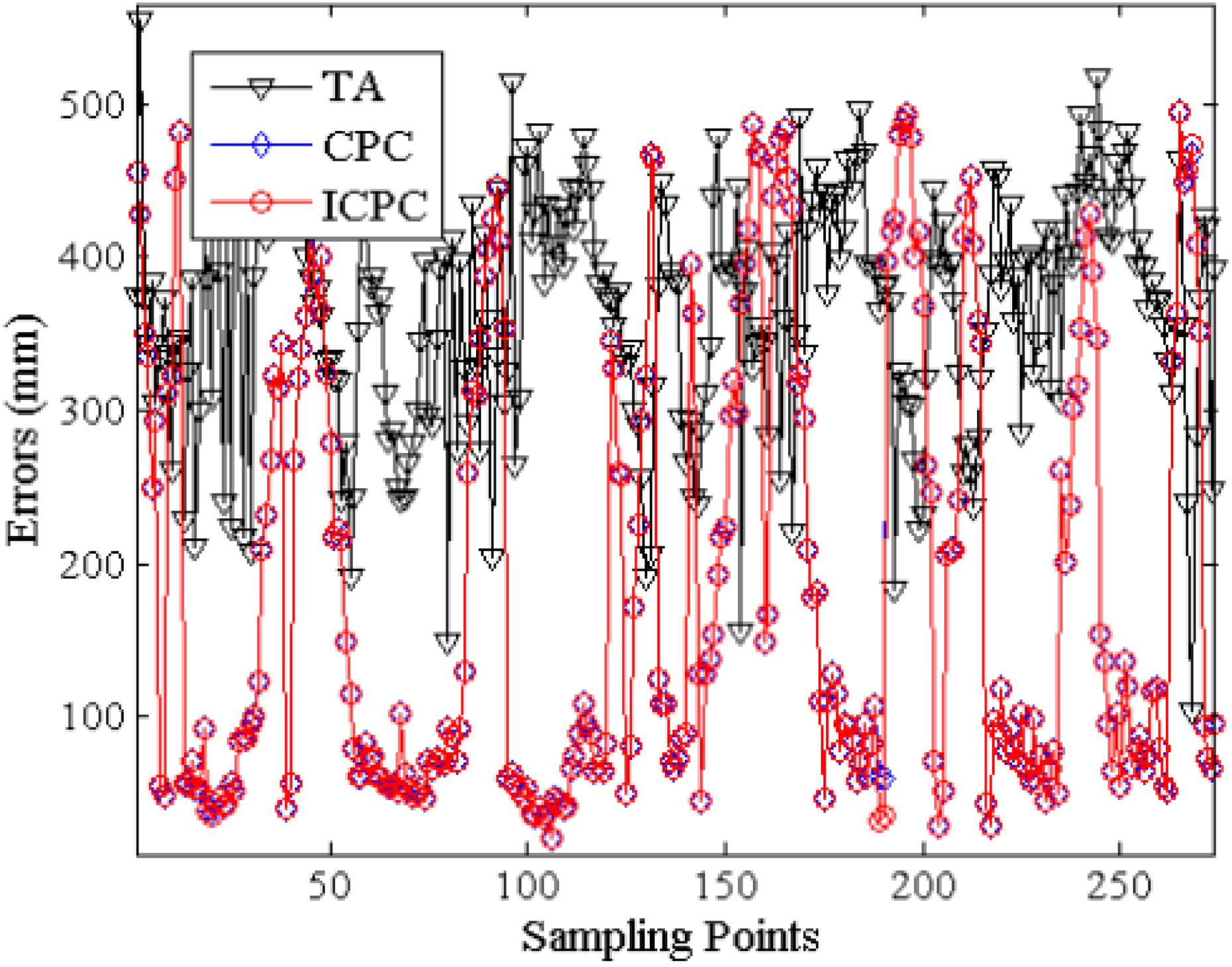
The localization errors of single object.
Figure 31 depicts the wireless communication environment. The majority of samplings have received transmission packages from two views. Only eight samplings have received data from three views. It means that the proposed algorithms can only provide one center point in Figure 7. It will greatly affect the localization accuracy of the proposed algorithm. Especially, ICPC algorithm cannot function well, and there are no center points above the base plane. It leads to the same estimated location between CPC and ICPC algorithm as shown in Figure 29.

The wireless transmission in WMSNs. WMSN: wireless multimedia sensor network.
Conclusions
A 3D localization algorithm based on the concept of common perpendicular has been presented for the experimental platforms of CNs and WMSNs. It is extended to the dynamic localization of mobile robots, which is the single- or multi-object tracking. The proposed single-object tracking relies on background subtraction that has been shown to be valid for a suitable camera setups and object motions. The proposed multi-object tracking employs the color algorithm to build the color models based on the color appearance. The performance of the localization algorithm has been demonstrated, not only for camera calibration on the different types of lights and illuminations, but also for the underlying problems of real-time single-object 3D localization, as well as for multi-object 3D localization from multi-view. The experimental results show that it can effectively realize the high localization accuracy, overcome the side effects of shadow detection, and can be extended to follow-up experiments. Future work will cover the extension of the proposed algorithm to the smoothness and continuity of trajectory by the filters, and a comparative study of these approaches for WMSN-based 3D localization as well as for collaborative calibration.
Footnotes
Declaration of conflicting interests
The author(s) declared no potential conflicts of interest with respect to the research, authorship, and/or publication of this article.
Funding
The author(s) disclosed receipt of the following financial support for the research, authorship, and/or publication of this article: This work was supported by National Natural Science Foundation of China under grant No. 61772018, General Research Project of Zhejiang Provincial Department of Education grant number Y201839944, Public Welfare Technology Research Project of Zhejiang Province grant number GG19F020015, Public Welfare Technology Application Research Project of Shaoxing City grant number 2018026059, and Research Foundation for Talented Scholars of Shaoxing University under grant No. 20185001.