
Abstract
Localization is a crucial part of autonomous moving for the indoor mobile robot. The natural features of the ceiling and surrounding environment can serve for position estimation. Based on these natural features, a hybrid visual natural landmarks–based localization method is proposed. We combine the landmarks-based positioning with ceiling-based visual odometry. During the visual odometry, the orientation is computed from the parallel features between the adjacent frames. The position is calculated from the corresponding point features in the two consecutive images using the perspective-n-point method. During the natural landmarks–based localization, the orientation filter is utilized to obtain the global orientation. Then, the feature points are determined by the Compute Unified Device Architecture–based scale-invariant feature transform algorithm. Finally, the position is estimated based on the computed orientation and point features. Various experiments have been conducted to evaluate the effectiveness of the proposed method. The experimental results show that the proposed localization method outperforms other methods in accuracy and efficiency.
Introduction
Self-localization is an important part of the autonomous mobile robot, especially the indoor service robot. Accurate position is necessary for navigation and trajectory planning, which play important roles in the mobile robot working in unknown indoor environment. Various localization methods have been proposed, such as Lidar, ultrasonic, WIFI, and Ultra Wideband. Recently, the vision-based localization has been intensively researched. Visual localization generally detects the existing features in the environment ranging from the artificial markers to geometric features such as corners and wall. 1,2 The position and orientation are determined by the corresponding features in the former and current frames. 3
It is common to place a known object such as barcodes in the environment to work as marks. Then, the position is estimated through the relative position of the marks and the robot. 4 The accurate calibration and recognition of the markers are needed in these methods. Moreover, the setting of the markers is not feasible in some applications. Another localization strategy is to employ natural landmarks. Thus, the vision-based simultaneous localization and mapping (VSLAM) is proposed, which uses the corner point and line features for 3-D reconstruction and Kalman filter for motion estimation. 5 –8 VSLAM can be generally classified into two categories: forward-looking approach 9 and side-looking approach. 10 In the forward-looking method, as the scale of the features in the view varies from frame to frame, the scale-invariant feature transform (SIFT) algorithm is adopted for features detection. 11,12 The side-looking method uses the corner-like features since small variation of the scale is caused when moving along the wall. However, complex computation is needed in VSLAM because of the search and matching of the features.
Related works
Earlier methods used the global camera mounted on the ceiling and the marker on the top of the robot to localize the robot. In Michel et al.’s study, 13 the overhead camera was adopted to estimate the pose of the robot, which is indicated by the marker. Andersen et al. 14 employed the lamp as the marker and computed the position of the automatic guided vehicle based on the global camera. The global vision-based localization method is also very popular in the soccer robot. 15 In the work of Brezak et al., 15 the position of the robot was calculated through the Bayer format image acquired by the global vision system, which achieved high precision.
To localize the robot without the artificial marks attached to the environment, the natural landmarks are proposed. Some researchers used corner, lamp, and door features to determine the position of the robot, which improved the ability to maintain the stableness of the algorithm. 10 In the study by Wu et al., 16 the line-based dynamic vision was adopted to detect the line-based visual features. This approach obtained the same result compared with other natural landmarks–based method, but also can be extended to the case with dependent lines.
Another typical natural landmarks–based localization method is the VSLAM. Heng et al. 9 proposed a VSLAM system with a multi-camera that used the stereo vision to estimate the pose with scale. In Kim et al.’s work, 5 the Bayesian filtering–based VSLAM was proposed, which reduced the error accumulation by selecting the key frames. However, these kind of methods have significant weakness: first, if the frame rate of the camera is low, the accuracy decreases obviously; second, the localization fails when there is sudden velocity change; at last, the real-time performance is hard to achieve. To solve this problem, Liu et al. 17 proposed the Conditional SLAM, which outperforms other methods in accuracy and computational efficiency.
In the previous stereo SLAM methods, the dense 3-D map is produced. Engel et al. 18 presented the semi-dense SLAM method by implementing loop closure detection and image alignment. Stereo and multi-view stereo were used to estimate the semi-dense map based on pose graph optimization. RGBD-SLAM methods are an important field in the research of visual SLAM. But the field of view (FOV) and depth range limit the application of the RGBD-SLAM method in the large-scale environment. Yousif et al. 19 combined the RGBD camera with a monocular camera to extract the 2-D and 3-D feature point at the same time, which could solve the unstable performance in the limited FOV and textureless scenes.
Other SLAM methods that focus on the direct approach, like the large-scale direct (LSD) SLAM, 20 have been proposed. In the LSD-SLAM method, the global map is presented as a pose graph, and the depth maps are estimated using filtering and direct image alignment. In Engel et al.’s work, 21 LSD-SLAM was extended to stereo vision. Recently, the stereo LSD-SLAM has been integrated with inertial measurement unit (IMU) through solving energy minimization problems, which would be challenged with the photometric error. Leutenegger et al. 22 fuses the visual and inertial cues which integrate the visual reprojection error with IMU error into the cost function, and then solve the joint function to infer about the motion.
Motivations
In the artificial marker–based methods, the mismatching of the markers will result in large errors of localization. Thus, the markers must be designed in specified shape and color, and then set in positions selected in advance. Triangulation of the landmarks is generally needed in the measurement of the position of the robot, which decreases the accuracy and efficiency. The main concerns of the VSLAM method is the visual odometry and close-loop property. However, the visual odometry is extremely sensitive to the environmental change and cannot solve the problem of error accumulation. Image processing and data fusion have to be implemented to achieve close-loop property.
Recently, the ceiling-based localization method was proposed in some articles as the features of the ceiling are rarely occluded and stable in the scale. Moreover, the localization is not affected by the dynamic change such as moving people in the environment. In the study by Xu et al., 3 the perspective-n-point (PnP)-based localization method was presented, in which the position and orientation are computed through the point features and line features on the ceiling. Similarly, in the research of Jeong and Lee, 23 the VSLAM used line and corner features as landmarks. The hybrid landmark outperforms the single one.
Based on the survey and analysis of the existing localization algorithms, the hybrid visual natural landmark (HVNL)–based method is proposed. First, a landmark library is built for absolute positioning including the features extracted from the ceiling image and the panoramic image. Then, the robot must determine whether there exists natural landmark. If the natural landmark exists, the panoramic image is used to compute the orientation and the ceiling image is used to estimate the position of the robot; otherwise, the ceiling-based visual odometry method is adopted, which localizes the robot using the different locations of the matching features in two adjacent frames. During the selection and matching of the features, the Graphics Processing Unit (GPU) acceleration is implemented to improve the efficiency and accuracy, respectively. Comprehensive experiments were conducted, and the results demonstrated that the proposed method outperforms the visual odometry in accuracy and VSLAM in efficiency.
Organization of the article
The rest of the article is organized as follows. The second section introduces the pipeline of the proposed method. The establishment and recognition of the natural landmarks are presented in the third section. The ceiling-based visual odometry is described in the fourth section. In the fifth section, the natural landmark–based localization is introduced. The experimental results are presented and analyzed in the sixth section. The seventh section gives the conclusion.
The proposed localization system
In the indoor environment, some of the ceiling consisted of chessboard blocks. An RGB camera and omnidirectional camera 24,25 are mounted on the top of the robot, which is shown in Figure 1. The world frame is assigned on the ceiling. The X and Y axis of the world frame are parallel to the edge lines of the blocks. The camera coordinate is set to the same as the image frame. Thus, the Z axis is normal to the plane of the ceiling.

Diagram of the HVNL-based localization system. HVNL: hybrid visual natural landmark.
The proposed localization system mainly consists of four parts: (1) landmark library establishment; (2) recognition of the natural landmarks; (3) ceiling-based visual odometry; and (4) hybrid natural landmark–based localization. The flow diagram of the localization algorithm is shown in Figure 2. From Figure 2, it can be known that the visual odometry is actually a relative localization and the natural landmark–based positioning is equivalent to absolute localization. Thus, the hybrid localization strategy can achieve better performance than other methods.
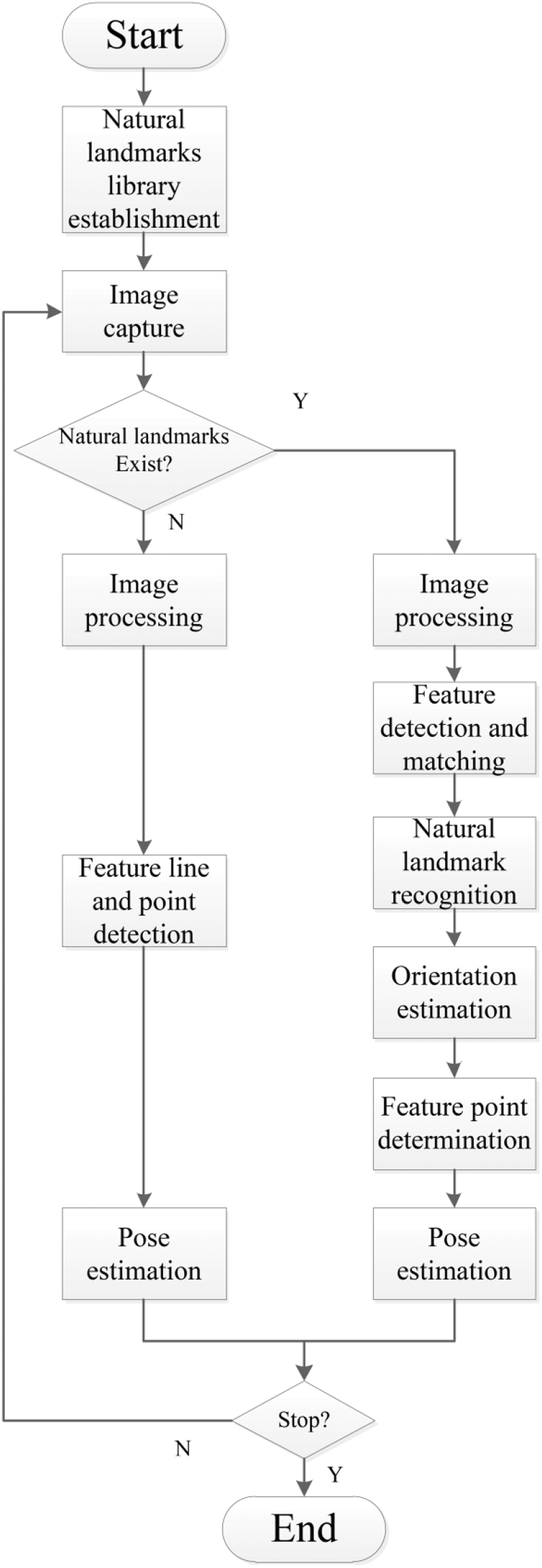
Block diagram of the proposed localization method.
Natural landmark establishment and recognition
The accumulation error is unavoidable during the longtime moving of the robot that localizes based on visual odometry. Especially if the robot moves along a closed trajectory, the error will not be removed even the position is nearby the starting point. In the former research, 4 the artificial markers were adopted to eliminate the error. In this study, the hybrid natural landmarks are used. First, the robot has to navigate the environment as a mapping run to establish the landmark library. The most important part of building and recognizing the natural landmark lies in the feature detection and matching. Various methods have been proposed to detect and match the image features, which can mainly be classified into two categories: intensity-based methods 26 and feature-based methods. 11,27,28
The intensity-based methods are usually limited by the illumination differences, textureless regions, and computational efficiency. 29 Thus, the feature-based methods, including point, line, contour, 30,31 and so on, are widely used. Some representative feature-based methods have been presented in recent research studies, such as SIFT, 12,32 SURF, 33 GLOH, 34 and BRISK. 35 The SIFT-based method outperforms other algorithms because of its invariant image rotation, scaling, and illumination variations. In this article, a discrete Gaussian–Hermite moment (DGHM) 36,37 –based feature detection method is proposed to build the landmark library. Then, the Compute Unified Device Architecture (CUDA)–based SIFT algorithm is adopted to recognize the natural landmark, which largely speeds up the process of localization.
Establishment of the natural landmark library
Yang and Dai 36 proposed the Gaussian–Hermite moments based on weighted Hermite polynomials, which were invariant to rotation and translation.
In this article, the DGHM-based feature detection algorithm is proposed. More explanation of the GH moments is shown in Appendix 1. The DGHM at (i, j) can be expressed as

Assume the image mask is t(u, v), the size is

The feature points detected by the DGHM-based method are more stable and contain more geometric information.
30
The approximate value of the determinant of

where ω is the weighted coefficient. Then, the feature point can be determined according to whether the determinant is positive or negative. If it is positive, then the current point is the feature point.
In this study, the hybrid natural landmark is proposed, which contains the ceiling image features and the panoramic image features, shown in Figure 3. The selection of the natural landmark largely affects the accuracy and efficiency of localization. Too many landmarks reduce the efficiency and too few landmarks cause low accuracy. We set the starting point as the first landmark. Then, the panoramic image is adopted for feature detection and matching with respect to the features in the landmark library. If the number of the matching feature point is less than T, it can be known that the current point is far away from the existing natural landmarks. Then, the current point is defined as the new landmark and assigned with ID number.

Hybrid natural landmark library. (a) Panoramic images and (b) ceiling images.
Recognition of the natural landmark
In order to localize the robot, the accurate recognition of the natural landmark is necessary. After the natural landmark library finished, each natural landmark must be matched separately. Features detection and matching are very useful for natural landmark recognition because they are widely distributed in the environment. In previous research, 21,26 the SURF and SIFT methods are usually adopted. However, the SIFT method is time-consuming and the SURF method is less accurate compared with other methods. In this article, the CUDA-based DGHM-SIFT algorithm is proposed to recognize the natural landmark. First, the DGHM-based feature detection method is used to find the feature point, and then the CUDA-based SIFT descriptor and matching is implemented to determine the referenced natural landmark for localization. As the DGHM has good edge detecting property, the acquired feature points have significant geometry feature information and are more stable. Thus, the proposed method is more robust.
After the key points are detected, the gradient table of the image in the Gaussian pyramid is prepared. Each image in the Gaussian pyramid is defined as one octaves. Then, the descriptors of the key point which belongs to the same octave are generated simultaneously. The GPU implementation of the proposed method is shown in Figure 4. The recognition results are shown in Figure 5.
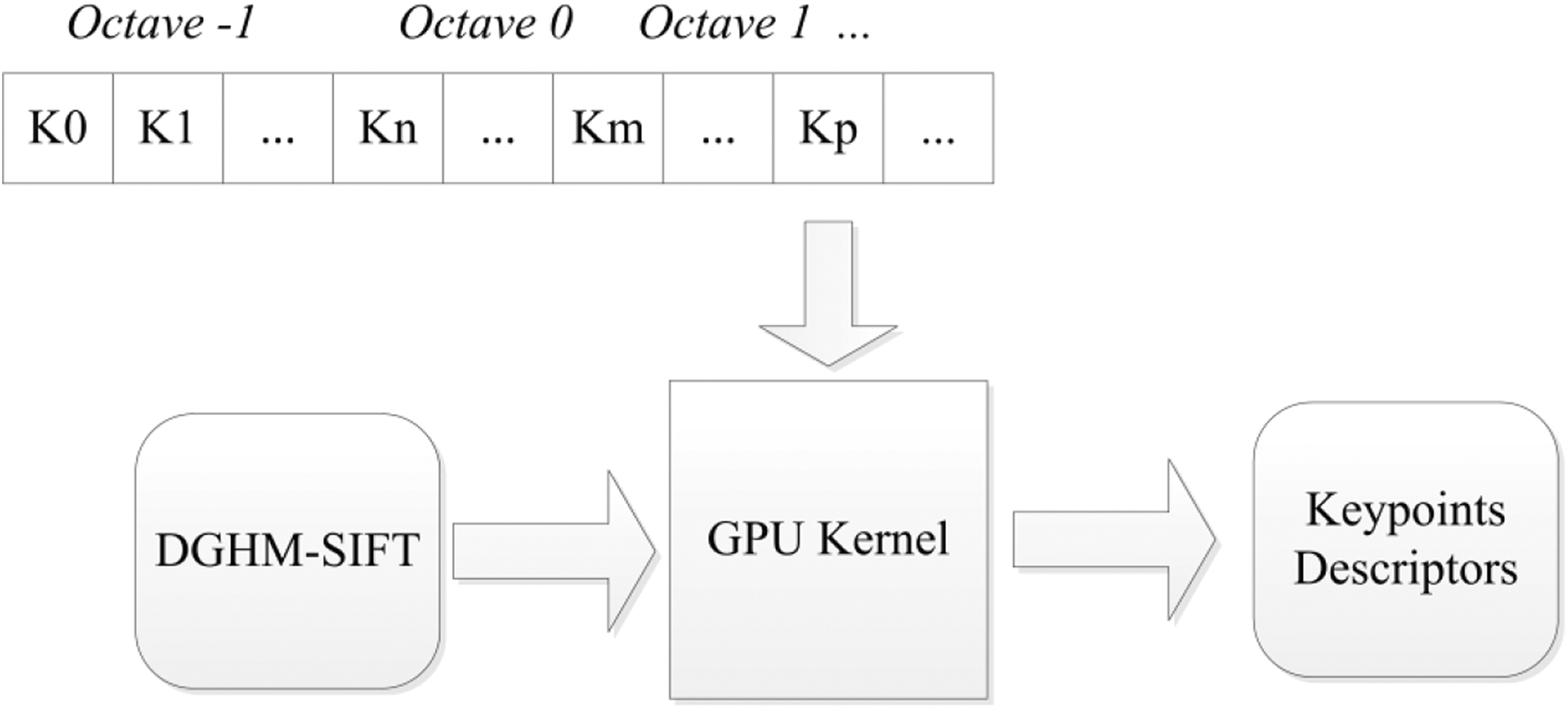
GPU implementation on the recognition of the natural landmark. GPU: graphics processing unit.

Natural landmark recognition results. (a and b) Successful recognition and (c) failed recognition.
Ceiling-based visual odometry
The feature of the ceiling can be reliably detected as it is less possible to be occluded. The ceiling commonly consists of many blocks, which have parallel lines and corner points. The point and line features are very useful for the localization of the robot. The position of the robot can be determined with the orientation information. However, any point cannot be guaranteed to be observed in the camera image at all the time. Thus, it is impossible to localize the robot only with fixed feature points. They should be selected dynamically with the motions of the robot. The block diagram of the ceiling-based visual odometry is shown in Figure 6 and described as follows. The raw image is calibrated with the intrinsic parameters. The image is set as reference. The following images are used for estimating the position based on the reference. The feature lines are extracted, then the intersection point of the feature lines, which is the closest to the image center, is selected as the initial feature point. With the motions of the robot, the feature lines and points are tracked and updated around that of the former image. The position is estimated based on the feature lines and points. If the feature point is far away from the image center, the algorithm returns to (2); otherwise, returns to (4).

Block diagram of the ceiling-based visual odometry.
Image processing
Due to the illumination difference, there usually exist some blurs nearby the lines and corners of the blocks in the ceiling. This results in
the wrong feature extraction and recognition. Thus, filtering is needed to process the image and acquire more accurate features. In this article, the weighted guided filter (WGF) 38 is adopted, which has good edge-preserving property. As the computational complexity of the WGF is irrelevant to the size of the support window, it can achieve real-time performance. The kernel function can be written as

where

In equation (4), G is the guidance image and I is the input image. Here, we define the input image as the guidance image.

where q is the neighboring point of the window centered at p. Z(p) is the output value of the filter at p. ε is a constant.
After processing the image with WGF, the Hough transform 39 is used to detect the feature lines. The Hough transform finds the specified shape from the given objects through voting, which makes it less efficient. Thus, the hybrid feature detection method is adopted to reduce the computational complexity. The global feature detection is only implemented for the reference image. And for other images, the local feature detection method is used nearby the feature point in the last frame.
For the reference image, all lines are extracted from the binary image. The line representing the X axis of the world coordinate, which is the closest to the center of the image, is defined as the main line. Another line that is the closest to the center of the image and vertical to the main line is defined as secondary line. The intersection of these two lines is defined as the main feature point. For the other image, the region-of-interest (ROI) method is utilized to improve the computational efficiency. A rectangular window center at the main feature point of the former image is determined. Then the local feature detection method is implemented within the window. The main and secondary lines and feature point are tracked and updated. If the feature point is not in the current image, the former image is set as the reference image and the new feature lines and point are determined.
Positioning based on visual odometry
The transformation matrix from the world coordinate to the camera coordinate can be expressed as

where

Frames of reference.
As the mobile robot only moves along the Xw , Yw axis and rotates along the Zw axis, the transformation matrix from the camera coordinate to the world coordinate can be expressed as


where
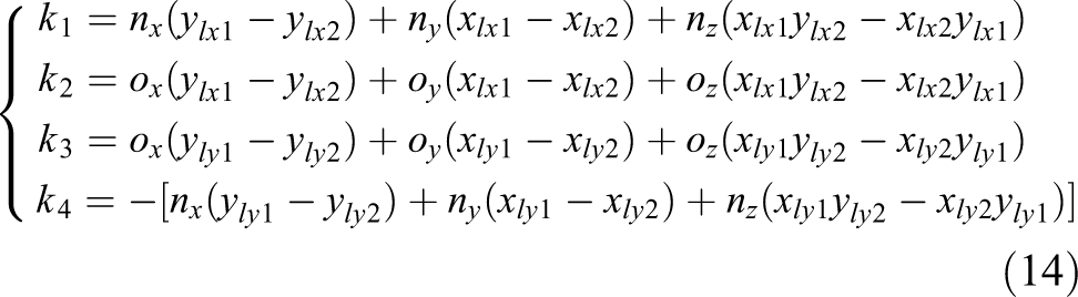
The orientation of the robot is crucial for the pose estimation. Due to the existence of the parallels on the ceiling, for any two points, which are parallel to the

where

Combining equation (9) and (10) we have

From equation (12), the rotation angle of the robot can be obtained as

where
For the (i+1)th frame, we have

where
Then, we have
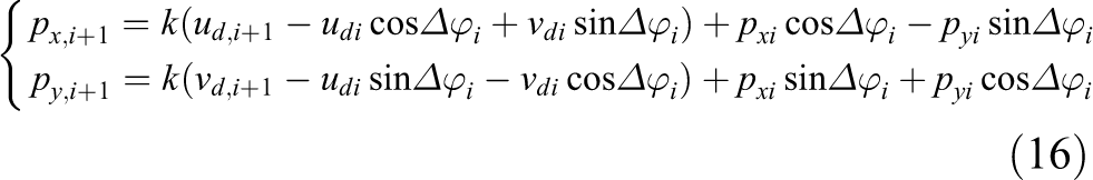
In the previous research, 3 the position is estimated from the former and current frames, and then accumulated. In this article, the position is determined only by the reference frame and current frame, which can reduce the accumulation error effectively. Therefore, the pose of the robot can be written as

where

where
Natural landmark–based localization
In the case of artificial landmark–based localization, the process of landmark recognition would be effected by the human activities. Sometimes, the landmarks are even occluded by some objects, which will lead to failure in localization. The visual odometry method is efficient and can achieve real-time performance, but the accumulation error cannot be removed with the motion of the robot. The initial position of the robot cannot be determined at the beginning. To solve these problems, the hybrid visual landmark–based localization method is proposed, which has the advantages of robustness and absolute localization.
Orientation estimation
For a general purpose, the orientation filter is adopted to estimate the orientation angles. In our study, the indirect Kalman filter 40 is utilized, which defines the state space with the orientation error. The state vector usually has to be unit or positive, but it is not necessary in the proposed filter. Moreover, the state propagation and measurement model is simpler than other filters. The data fusion process is described by the error quaternion, which is an approximately linear space.
Assume the relative orientation from the current image I to the reference image G of the natural landmark is denoted using the unit quaternion

where ⊗ represents the multiplication operation.
We use Δ q to denote the rotation between two adjacent frames. Then, we obtain

Based on the assumption that the error estimate δq is normal distribution, we have

where

Combining equations (21) and (22), we have

where Δ
R
is the rotation matrix. It can be found that

where

The state model can be expressed as
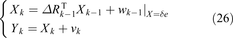
where w is the process noise and v is the observation noise. As mentioned above, Xk, Yk are closer to linear, thus, they can be thought as decoupled with each other. Then, the covariance matrix of w and v, which is denoted by Q and W, can be set to diagonal. In this article, the IMU is adopted to obtain more accurate orientation estimation. The covariance matrix Q is estimated by the visual odometry and W is estimated by the IMU. Finally, the output of the filter can be written as

where

where
Position
To compute the position of the robot, the feature points must be determined in the current image and reference image of the natural landmark. In this study, the lamp features are used to determine the feature point as they can be easily detected. In some previous research, 10 the lamps are usually detected when they are turned on, which is not possible for all cases. Thus, the DGHM-SIFT algorithm described in the “Recognition of the natural landmark” section is adopted to determine the feature point.
First, the lamp features are detected based on the intensity, which is obviously different from other blocks. Then, the ROI is selected with a window centered at the corner of the lamp. The corner that is nearest to the center of the image is selected as the main feature point. Finally, the DGHM-SIFT algorithm is utilized to find the corresponding lamp in the ceiling image of the natural landmark. The lamp corner is set to be the feature point. The feature point detection results are shown in Figure 8. The white circle means the feature point.

The feature point detection results (the lines connect the corresponding matching points).
After the orientation and feature point is determined, the localization can be implemented according to the “Positioning based on visual odometry” section, as given in

where
Experimental results
The experimental system contains a mobile robot (TurtleBot, Yujin Robot, YMR-K01-W1), an RGB camera, a fish-eye camera, and IMU. The two cameras are pointed to the ceiling, as shown in Figure 9.

Experimental system.
Visual odometry experiment
An indoor experiment was implemented to verify the effectiveness of the visual odometry. Before moving, the initial position of the robot must be determined. The PnP-based 41 method was adopted to compute initial pose using the vertices of the blocks. The transformation matrix could be determined

where

After the initial pose of the robot was obtained, the robot started moving. The experimental results are shown in Figure 10. For better evaluation, the position results are shown in Figure 10(a). From Figure 10(a), it can be found that with the increasing moving distance, the computed trajectory deviates from the actual one. The position errors, which are the distance from the measure point to the actual point, are presented in Figure 10(b). The maximum error in distance was 49.71 mm. The average position error along Xw and Yw axis was 18.30 mm and 18.20 mm, respectively. Thus, the error accumulation was very small as the localization is implemented based on the reference image instead of the former image.

Position results of the visual odometry. (a) Positions and (b) position errors in distance.
The orientation results and its error are shown in Figure 11. The orientation was denoted by the direction angle in the world frame, without affected by the error accumulation. The average error of the orientation angle was 0.78° in our experiment. Moreover, the maximum error is 1.12° because of the noise and illumination difference in the images. The experimental results demonstrate that the visual odometry has small error in orientation, but the error accumulation is unavoidable.

Orientation results of the visual odometry. (a) Direction angles and (b) orientation errors in angles.
Initial pose estimation
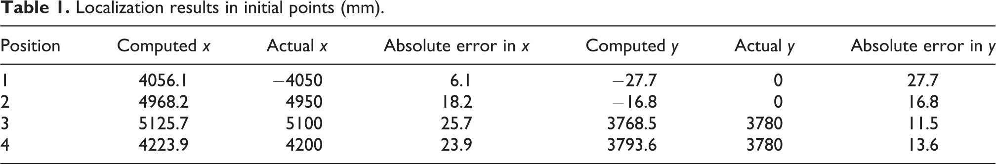
The biggest difference between the visual odometry and the landmarks-based methods is that the landmarks-based methods could estimate its initial pose in any positions instead of computing it based on former images. To evaluate the effectiveness of the proposed method, some experiments on initial pose estimation were conducted. In this article, four random points were selected as the initial positions, the localization results of these four points are shown in Table 1. From Table 1, it can be found that the maximum error of the initial pose estimation in distance is 29.2 mm, which can be used as the initial position for the following images.
Localization results in initial points (mm).
Experiments on VNL-based method
After the initial pose in the world frame was determined, the localization of the robot is implemented based on the VNLs. The proposed localization method described in “The proposed localization system” section was repeated for position estimation. The measured and actual pose of the robot are shown in Table 2. From Table 2, it can be known that the average errors in the x and y axis are 12.9 mm and 13.0 mm, respectively. The maximum error in distance is 29.5 mm. The average error of the direction angle is 0.7°. Compared with the visual odometry, the position error was not accumulated in the proposed method. In other words, it can achieve high accuracy and outperform the visual odometry methods in the long distance movement.
Localization results of the VNL-based method.

VNL: visual natural landmark.
Comparison experiments
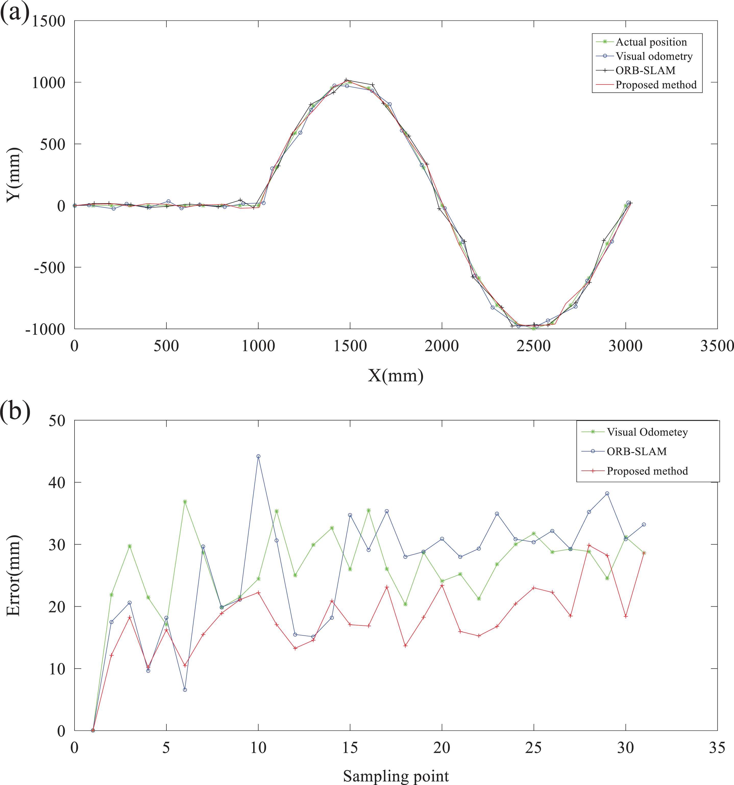
To obtain a more comprehensive evaluation of the performance of the proposed method, some comparison experiments had been implemented. Three methods were compared in this experiment, including visual odometry, ORB-SLAM, 42 and the proposed method. The ORB-SLAM method is an accurate and versatile solution for monocular, RGB-D, and stereo visions, which can achieve real-time performance in the position estimation and 3-D reconstruction. In ORB-SLAM, the keyframe-based strategy was taken to boost the reusability of the maps. The experimental results are shown in Figures 12 and 13. The results demonstrate that the proposed method achieves higher accuracy than the visual odometry and ORB-SLAM. The computation time for each method is listed in Table 3. From Table 3, it can be found that using GPU obviously accelerates the localization, which makes the proposed method achieve real-time performance with high accuracy.

Positioning results with the odometry, ORB-SLAM, and proposed method. (a) Positions and (b) position errors in distance. SLAM: simultaneous localization and mapping.
Positioning results. (a) Positions, (b) position errors in distance, (c) orientation angle, and (d) angle error.
Average runtime for each method.

HVLN: hybrid visual natural landmark; SLAM: simultaneous localization and mapping; GPU: graphics processing unit; CPU: central processing unit.
To verify the robustness of the proposed algorithm against the illumination variation, we conducted experiments under different light conditions: natural light, weak light (evening), and strong light (sunny/noon). The experimental results are shown in Table 4. It can be seen from the table that the traditional ORB feature points are less robust when the illumination conditions change. Different feature extractions at the same location in different time periods may cause mismatching of maps. The accuracy of the positioning algorithm we proposed does not change greatly even under different conditions.
Localization error under different conditions (mm).

HVLN: hybrid visual natural landmark; SLAM: simultaneous localization and mapping.
Conclusion
In this article, the ceiling features and environment features are detected and used as natural landmarks. Before localization, the natural landmark library is established. During the localization, the robot must determine the existence of the natural landmarks. The CUDA-based SIFT method and orientation filter are adopted for the natural landmarks–based localization. The lines and points feature on the ceiling are utilized for the visual odometry–based pose estimation. The proposed HVLN method was validated by various experiments. The following conclusions are drawn,
The ceiling-based visual odometry detects the line and point features according to the blocks and parallels on the ceiling. Then, the orientation angle is determined by the corresponding lines in the two adjacent frames. The position is estimated based on the orientation and feature point, which is efficient and accurate in the short distance.
In the natural landmarks–based localization, the orientation filter is used to calculate the orientation angle. The CUDA-based SIFT method is implemented to find the corresponding feature point in the current frame and library frame. This method is a little more time-consuming than the visual odometry, but it can compute the initial position without error accumulation.
The proposed HVLN algorithm combines the relative localization and absolute localization. Therefore, it can work more efficiently and accurately than other positioning methods.
The future work is to analyze the error and find the relationship between the orientation error and position error, which will be beneficial to the position accuracy.
Footnotes
Acknowledgements
The authors would like to thank the National Natural Science Foundation of China, the Hangzhou Civic Significant Technological Innovation Project of China, and the Hangzhou Civic Significant Technological Innovation Project of China for supporting this work.
Declaration of conflicting interests
The author(s) declared no potential conflicts of interest with respect to the research, authorship, and/or publication of this article.
Funding
The author(s) disclosed receipt of following financial support for the research, authorship, and/or publication of this article: This work was supported by the National Natural Science Foundation of China (grant no. 51521064), the Hangzhou Civic Significant Technological Innovation Project of China (no. 20131110A04), and Hangzhou Civic Significant Technological Innovation Project of China (no. 20142013A56).
Supplemental material
Supplemental material for this article is available online.
Appendix 1
The Hermite polynomial can be written as
The
where
where the initial conditions are
With a scale parameter σ, the Gaussian–Hermite polynomial can be defined as
The Gaussian–Hermite moments are formed by a set of Gaussian–Hermite polynomials. Given an image I, and the intensity function is
Given the intensity function
where
The gravity center over [−1, 1] can be obtained by the geometric moments
Then, the central Gaussian–Hermite moments can be expressed as
References
Supplementary Material
Please find the following supplemental material available below.
For Open Access articles published under a Creative Commons License, all supplemental material carries the same license as the article it is associated with.
For non-Open Access articles published, all supplemental material carries a non-exclusive license, and permission requests for re-use of supplemental material or any part of supplemental material shall be sent directly to the copyright owner as specified in the copyright notice associated with the article.