
Abstract
This article presents a self-localization scheme for indoor mobile robot navigation based on reliable design and recognition of artificial visual landmarks. Each landmark is patterned with a set of concentric circular rings in black and white, which reliably encodes the landmark’s identity under environmental illumination. A mobile robot in navigation uses an onboard camera to capture landmarks in the environment. The landmarks in an image are detected and identified using a bilayer recognition algorithm: A global recognition process initially extracts candidate landmark regions across the whole image and tries to identify enough landmarks; if necessary, a local recognition process locally enhances those unidentified regions of interest influenced by illumination and incompleteness and reidentifies them. The recognized landmarks are used to estimate the position and orientation of the onboard camera in the environment, based on the geometric relationship between the image and environmental frames. The experiments carried out in a real indoor environment show high robustness of the proposed landmark design and recognition scheme to the illumination condition, which leads to reliable and accurate mobile robot localization.
Introduction
This article presents an onboard localization scheme for autonomous mobile robots working in indoor environments, based on reliable design and recognition of artificial visual landmarks, targeting to device a convenient and economic while reliable and accurate localization technique to support indoor applications of autonomous mobile robots.
Self-localization is a fundamental problem in autonomous mobile robotics. 1 Many off-the-shelf mobile platforms have the built-in capability of relative self-localization, that is, a mobile robot can estimate its own position and orientation incrementally based on the feedback of onboard sensors such as encoders, gyros, and accelerometers. The main disadvantage is that the localization error is accumulative with respect to the time and distance. In the past decades, absolute self-localization techniques for mobile robots have received a lot of attention, where a mobile robot refers to beacons or landmarks in the environment to estimate its position and orientation without error accumulation. While global positioning system has become a well-accepted solution for outdoor localization, a number of approaches have also been proposed for indoor localization of mobile robots.
Range-based indoor localization by referring to beacons at known positions has been extensively studied. Ultrasonic, 2 radio-frequency (RF), 3 and infrared 4 signals are typically used as ranging signals. Representative methods of range estimation include time-difference-of-arrival estimation (TDOA), 5 time-of-arrival estimation (TOA), 6 angle-of-arrival estimation (AOA), 7 and received signal strength indicator (RSSI). 8 Main problems with range-based indoor localization include the deflection of signals, interference among signals, signal cross talking at receivers, and asynchrony among sensors, which may significantly affect the reliability and accuracy of localization. Moreover, it does not provide direct estimation of orientation.
Without the above issues of range signaling, vision-based indoor localization by capturing landmarks at known positions has also caused a lot of attention. The use of artificial landmarks simplifies the landmark recognition process and compensates for the instability of natural landmarks. 9 Kabuka and Arenas 10 presented a design of wall-attached landmarks consisting of a circular pattern and a barcode, and located a mobile robot based on the geometric parameters of the imaged landmark. Becker et al. 11 presented a design of ceiling-attached landmarks consisting of an outer circle with an opening and an inner 3 × 3 grid of black and white tiles, and localized a mobile robot based on the mapping between the image plane and workspace. Ogawa et al. 12 presented a design of ceiling-attached landmarks based on a circular mark pattern with the identity defined by the binary gray code around the mark, and measured the horizontal distance to the landmark based on the length to width ratio of the landmark image and the tilt angle of the camera. Guo and Xu 13 presented a design of vertical surface-attached landmarks consisting of symmetric rectangles and seven-part numbers, and located a mobile robot in two-dimensional (2-D) space using bilateration. Wen et al. 14 presented a design of ceiling- or wall-attached landmarks with a pentagon shape and the identity defined by binary BCH code, and located a mobile robot based on the homography between the landmark plane and image plane. Li and Yang 15 presented a design of landmarks consisting of a 0–9 number on a red square board, recognized landmarks using a genetic algorithm approach, and estimated the distance of a landmark based on its size in image. Kim et al. 16 presented a design of ceiling-attached hybrid landmarks which placed three light-emitting diode in a right-angle triangle arrangement around an RF Cricket range sensor to facilitate landmark detection. Li and Jiang 17 presented a design of landmarks consisting of a white pattern on a deep blue background, and used a color thresholding method to extract landmarks from images. Rusdinar et al. 18 adopted a design of ceiling-attached landmarks which used a grid of circular dots to represent identity and direction. Nikitenko et al. 19 presented a design of square landmarks which used glyphs to encode the identity. Shih and Ku 20 presented a design of ceiling-attached landmarks consisting of a blue character on a yellow background, and detected landmarks based on color detection and computation of feature points. Lébraly et al. 21 presented a design of landmarks consisting of a bull’s-eye and a surrounding circular code, which was originally designed for camera calibration but can also be used for mobile robot localization. In a related work, Liu and Zhou 22 presented a visual trilateration algorithm to onboard estimate the three-dimensional position and orientation of a mobile robot from a single onboard image of landmarks.
While range-based self-localization depends on signaling-based range estimation, landmark-based self-localization often uses vision-based range estimation. Landmark-based self-localization is generally advantageous over range-based self-localization in the robustness to the dynamics of robots, accuracy in localization results, and ability to estimate orientation. However, in spite of extensive research, it is still difficult to find a low-cost off-the-shelf onboard localization system based on artificial landmarks with high reliability, accuracy and update frequency for low-budget indoor operations and experiments of mobile robots, particularly for multi-robot systems. From the system point of view, the main challenge is to comprehensively consider the landmark design, landmark recognition algorithm, and hardware configuration in order to attain reliable, accurate and frequent onboard localization at low system cost. From the technical component point of view, existing landmark designs and recognition algorithms count on the detection of complete landmarks, while the robustness of landmark recognition to the influence of environmental illumination condition, especially landmarks next to light sources, and incompletely captured landmarks, has been generally lack of discussion in the literature of mobile robot localization. Although landmark recognition in lighting condition was checked in the study of Rusdinar et al. 18 for their landmark design, due to the distance of the landmarks to the light sources, the level of the influence of lighting needs further clarification.
Meanwhile, several designs of fiducial markers which were originally introduced for pose tracking in augmented reality (AR) applications can potentially be used as landmarks for mobile robot localization. Knyaz and Sibiryakov 23 presented a design of coded targets consisting of two concentric circles and a few small black dots between the circles to binary code the identity. Naimark and Foxlin 24 presented a design of circular data matrix fiducial consisting of two concentric outer and inner rings and two in-between data rings with sectors encoding the identity. In the past decade, square-shaped fiducial marker systems have received substantial research attention. In general, they adopt a square black boarder to facilitate marker detection and pose estimation and use the inner region to code the identity. Matrix markers 25 use binary matrix code for identification. ARToolkit system 26 uses an internal pattern to code marker identity, detects marker borders by tracking connected pixels, and identifies markers by template matching. ARToolKitPlus system 27 made an improvement from ARToolkit by using binary pattern to encode marker identity and using automatic thresholding to facilitate marker detection. ARTag system 28 uses a binary coding scheme to define marker identity, detects marker borders by edge detection, and identifies markers based on binarizing the internal pattern according to a threshold of pixel intensity. Recently, Garrido-Jurado et al. 29 introduced ArUco system and made it available as a part of the OpenCV library. Their work presented a general algorithm to generate configurable dictionaries for binary coding of square markers to maximize the intermarker distance and the number of bit transitions. Their marker detection approach finds marker borders based on thresholding and identifies markers based on binarizing the inner region. Some works in this category considered the influence of lighting and partial occlusion on the robustness of marker detection and identification. Adaptive thresholding methods have been used to improve the robustness of marker detection, 27 –29 and binary coding schemes with error detection and correction have been used to improve the robustness of marker identification. 25,27 –29
Challenges still exist for applying these fiducial marker systems to mobile robot localization. The binarization of the internal pattern in these fiducial markers provides a compact design and identity coding strategy. However, in general, the resulting internal identity patterns are not geometrically symmetric. If we use these fiducial markers as landmarks, the reliability of landmark recognition generally depends on the reliability of decoding the internal pattern. However, ambient illumination condition, occlusion, and truncation by image boundary may cause landmarks to appear incomplete in images. The asymmetry of the identity pattern in these fiducial markers means a lack of geometric redundancy which complements the incompleteness. False landmark recognition may lead to invalid localization results. A solution to the partial occlusion problem in AR applications was proposed in the study of Garrido-Jurado et al. 29 based on using marker boards which are composed of multiple markers instead of using individual markers. For mobile robot localization, to ensure the detectability of the internal details of markers at a substantial camera-landmark distance and under a limited camera resolution, the size of each marker must be made sufficiently large. This will further lead to large marker boards, which is not quite desirable from the point of view of landmark installation/maintenance and space usage. Moreover, using marker boards results in higher computational complexity than using individual markers. Meanwhile, although the influence of lighting has been considered in some works, in general, light sources are far away from markers in applications, and there is a lack of discussion on the influence of light sources on very nearby markers.
In this article, we comprehensively consider the landmark design, landmark recognition and system configuration in landmark-based indoor robot localization. Our design of landmarks and algorithm of landmark recognition ensure high reliability in landmark recognition and result in minimal requirement in system configuration. Particularly, we introduce a simple and robust landmark design, and propose a reliable landmark recognition approach capable of dealing with the influence of ambient illumination condition and the incompleteness of landmarks. Our initial development was presented in the study of Zhong et al. 30 Comparing with that, this article fully develops our approach and makes it ready for generic applications. The main improvements include (1) the complete development of a general landmark design methodology applicable to different needs in the size of landmark set and (2) the complete development of a reliable landmark recognition algorithm adaptable to environmental illumination conditions and incompleteness of landmarks and ready for applications, validated through the extended experiments.
In the following sections, we will (1) present a system configuration of our landmark-based indoor localization scheme, (2) present our landmark design, (3) explain our landmark recognition algorithm, (4) describe a localization algorithm, and (5) report the experimental results. Our main contribution and the emphasis of this article will be on the landmark design and recognition.
Localization system
The localization system consists of the hardware and software components which work together to accomplish the landmark-based mobile robot self-localization.
The hardware side of the localization system (Figure 1) consists of artificial landmarks attached to the ceiling of the targeted indoor environment, which in general provides more tolerance to obstacles than other layouts, 31 –33 a regular forward-looking camera fixed on the mobile robot and facing the ceiling, which takes images of landmarks, and an onboard computer which processes the images of landmarks and estimates the position and orientation of the camera in the environmental frame.

Localization system.
The software of localization runs onboard. A landmark recognition algorithm detects landmarks from the image captured by the onboard camera and identifies them, adaptive to the ambient illumination condition and incompleteness of landmarks. A localization algorithm then estimates the position and orientation of the camera in the environmental frame, based on the positions of the identified landmarks and the geometric relationship between the image and environmental frames. Because the spatial relationship between the mobile robot and onboard camera is a fixed transformation, the estimation of the position and orientation of the camera is equivalent to that of the mobile robot.
Localizing a mobile robot based on concurrently captured multiple landmarks, the proposed self-localization scheme does not count on historical localization data and thus does not have the accumulative error as relative localization does. Instead, a navigating mobile robot can self-localize in a landmark environment whenever necessary. Moreover, since landmark recognition takes place completely onboard, the localization frequency is not affected by the number of mobile robots working in the environment. Thus, this localization scheme is well suitable to multi-robot systems.
Landmark design
The artificial landmarks are designed to facilitate reliable landmark detection and identification under the illumination condition of typical indoor environments and incompleteness of captured landmarks.
In our design, an artificial landmark is a planar pattern consisting of a set of concentric circular rings, including one black outer ring and a few black or white inner rings (Figure 2). The outer ring defines the boundary of the landmark; the inner rings encode the identity of the landmark. The pattern is printed on a regular nonilluminant paper. This design is simple, low cost, robust to the ambient illumination condition, and facilitates fast detection and reliable identification of landmarks from camera images.

Landmark design.
The black-colored outer ring isolates a landmark more reliably than other colors under varying illumination conditions, which contributes to the reliable detection of landmarks under the nonuniform illumination condition of real indoor environments.
The inner rings of a landmark encode the identity of the landmark. Numerically, the identity of a landmark can be encoded into a base-C numeral system, where C is a positive integer corresponding to the number of colors used to encode landmarks, for example, base-2 (binary) and base-8 (octal). The number of base-C digits, denoted by K, needed to encode a set of N different landmarks can be determined by

where ceil (X) denotes the nearest integer greater than or equal to X. Graphically, with the proposed ring-code design, each digit of the numerical identity code can be represented by an inner ring corresponding to the place of the digit in the numerical identity code and with a color corresponding to the value of the digit. The number of inner rings needed to encode a set of landmarks equals to the number of digits in the numerical identity code, K. Since in reality color information often becomes unstable under ambient illumination, this work only uses the black and white colors to encode the identity of landmarks, that is, C = 2. With such a binary coding system, we use K concentric inner rings to graphically represent a K-bit numerical identity code. Each inner ring (from outermost to innermost) is associated with a bit of the identity code (from right to left). A white inner ring represents 1, and a black inner ring represents 0.
The diameter of a landmark pattern (the outer diameter of the outer ring) and the width of each ring should be large enough for reliable landmark detection at a desirable distance. The pattern diameter is determined with a comprehensive consideration of the number of landmarks to be captured in the field of view of the camera, the number of landmarks used in the environment, and the detectability of the rings from the image. In order to use a landmark for localization, the rings in the landmark must be detectable from an image. The detectability of the rings is directly related to the capability of showing the rings in the image, which is affected by several factors, such as the physical sizes of the rings, the camera condition, and the distance between the camera and landmark. The landmark pattern must be sized such that the rings are detectable from the image, given the camera condition and camera-ceiling distance. A simple and effective strategy is to print out a landmark pattern at several different diameters, check the detectability from their images taken at the camera-ceiling distance, and choose a suitable pattern diameter.
The width Wi of the ith inner ring is defined as

so that each ring covers an equal amount of area, which facilitates the pixel-based detection of the regions of interest at a uniform strength across all the inner rings. Here,

where R0 denotes the radius of the landmark pattern. The resulting width of the outer ring is greater than that of the outermost inner ring, which contributes to reliable isolation of landmarks from images.
The uniform size and circularity of the landmark patterns facilitate the landmark recognition. In the localization system, the onboard camera faces generally perpendicular to the landmarks attached to the ceiling. With a limited field of view, a regular camera captures a limited number of landmarks of which the sizes in the image are nearly the same as each other. Thus, the uniform size of the outer rings provides a criterion for landmark detection. Moreover, under the limited field of view and the perpendicular view direction, the physically circular landmarks appear generally circular in the image, and can thus be directly compared with circular landmark templates for landmark identification. Besides, the geometric symmetry of the landmark design provides the desirable geometric redundancy, which complements the possible incompleteness of landmarks in the image caused by the illumination condition and image boundary. All these contribute to fast and reliable landmark recognition.
Landmark recognition
In general, the landmarks captured in an image are recognized through two steps: (1) landmark detection, which finds candidate landmark regions (CLRs), and (2) landmark identification, which determines the identity of each detected landmark. The landmark recognition algorithm is designed to reliably detect and identify the landmarks in images under the nonuniform illumination condition of typical indoor environments.
The algorithm takes a grayscale image of landmarks as the input (Figure 3). To work with a color camera, we can convert an RGB image to a grayscale image by eliminating the hue and saturation information while retaining the luminance. The input grayscale image is preprocessed to remove/reduce distortions based on camera calibration. 34
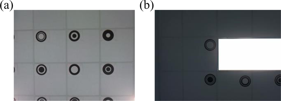
Input images under different ambient illuminations.
The image histogram is then analyzed (Figure 4). An image histogram presents the distribution of pixels across intensity values in a grayscale image. Based on the image histogram, a threshold intensity value for light source pixels is chosen, and all the pixels with the intensity value greater than the threshold are labeled as light source pixels. The ambient illumination affects the white balance of the vision sensor, which makes the pixels surrounding the light source appear less dark (Figure 3). This phenomenon affects the reliability of landmark recognition. The knowledge of the locations of light sources in the image helps the landmark recognition process deal with the effect of illumination and improves the rate of landmark recognition. After picking out the intensity values for light source pixels, the average background and foreground are extracted from the remaining peak intensity values of the image histogram, which will be used to assist landmark detection.
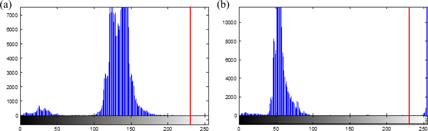
Image histograms (a) and (b) correspond to Figure 3(a) and 3(b), respectively. The vertical axis represents the number of pixels, and the horizontal axis represents the intensity value. The red line represents the chosen threshold value for the light source pixels.)
Considering both the reliability and speed of landmark recognition, the proposed landmark recognition algorithm is designed into a bilayer sequential structure consisting of a global recognition process and a local recognition process (Figure 5). First, the global recognition process is applied to the whole image to detect CLRs and identify landmarks. Second, if the number of identified landmarks from the global process is less than that needed for localization, the local recognition process is applied to locally enhance unidentified CLRs influenced by illumination and image boundary and reidentify them, which increases the rate of landmark recognition. In the flowchart, ROI stands for region of interest, CLR candidate landmark region, ICLR identified CLR, UCLR unidentified CLR, and DUCLR UCLR close to at least one light source or located on the boundary of the image.
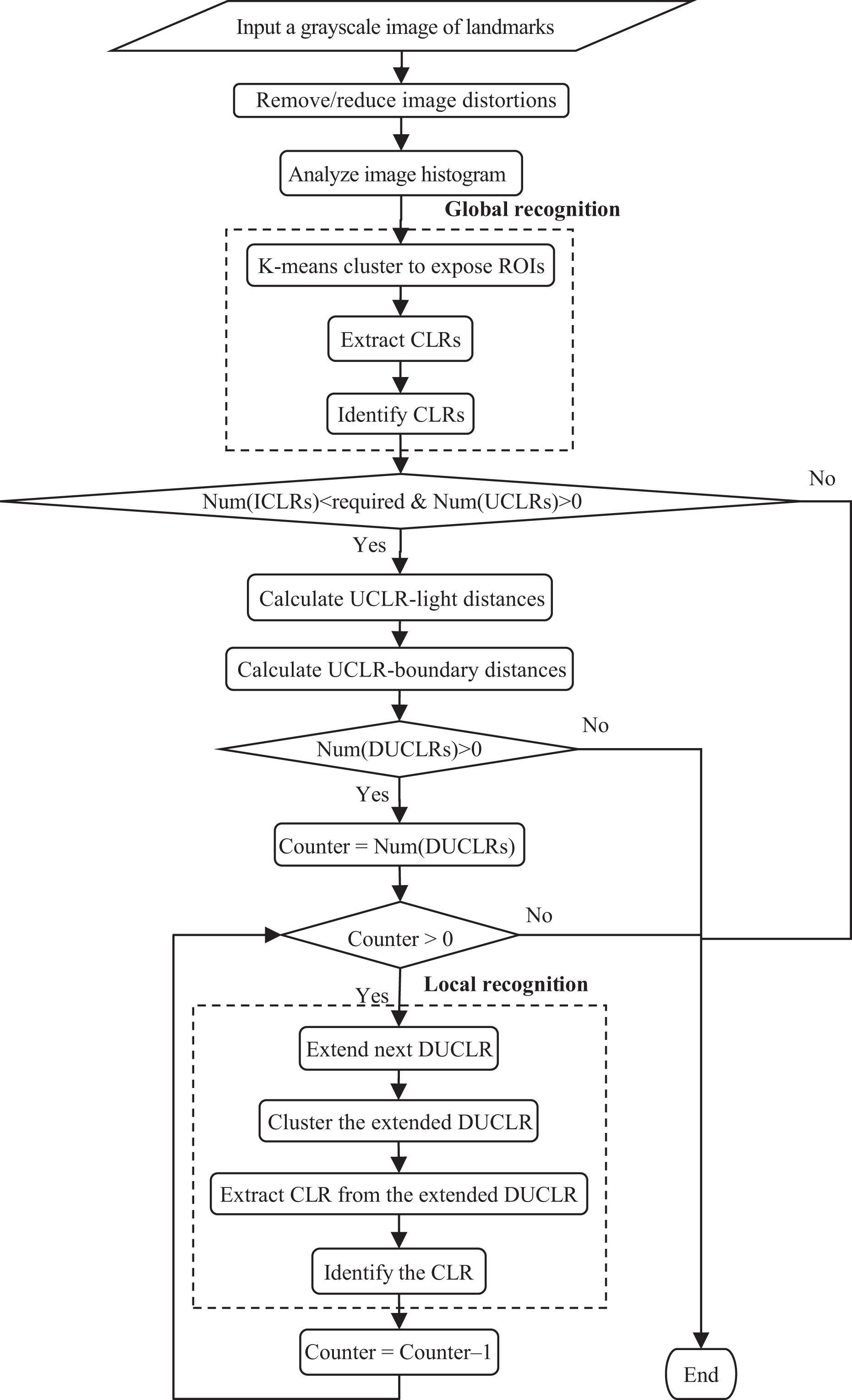
Flowchart of landmark recognition process.
Global recognition
The global recognition process labels ROIs and identifies landmarks across the whole image. The operations at this level are executed in the following order: image clustering, CLR extraction, and landmark identification.
Image clustering
The input grayscale image is processed using K-means clustering. 35 It partitions all the pixels in the grayscale image, excluding the light source pixels, into two clusters, “of interest” (which includes all ROIs) and “background” by minimizing the in-cluster sum of squared residuals of pixel intensity values. To facilitate fast and reliable clustering, initial values of K-means are chosen from the peak intensity values in the image histogram, excluding the light source pixels. By assigning the color of ROI pixels as black and that of background pixels as white, a binary image is generated (Figure 6).

K-means clustering ((a) and (b) result from Figure 3(a) and (b).)
CLR extraction
By labeling connected pixel regions, the black ROIs are extracted from the binary image. Tiny components with an area less than 10% of an inner ring are considered as noises and are removed without further processing. Internal ROIs, such as the black inner rings of landmarks, are labeled. We check if an ROI is contained by another ROI by comparing their external containing rectangles. If yes, it is considered a candidate black inner ring; if no, it is considered a candidate outer ring. Each candidate outer ring and the pixels encompassed by it define a CLR. Each CLR is cut out from the binary image using the external tangent rectangle of the outer ring.
Landmark identification
The global recognition process identifies only those CLRs with closed outer rings. Each CLR is identified by comparing it with the set of landmark templates. Each landmark template is a binary bitmap of the associated landmark pattern. A CLR is scaled to the size of a template. The degree of matching between a CLR and a template is defined using Pearson’s correlation coefficient 36 as

where ri,j
denotes the correlation coefficient between CLR-i and template-j,
For each CLR, the correlation coefficients with all the templates are calculated. If the maximal correlation coefficient is greater than a threshold, this CLR is regarded as identified, and its identity is given by the best-matching template (Figure 7); otherwise, this CLR is regarded as unidentified, which, if necessary, will be further processed by the local recognition process. For each identified landmark, the position of its center in the image is calculated as the geometric center of all its ROI pixels.

Identified CLRs from the global recognition process ((a) and (b) result from Figure 6(a) and (b), respectively. A yellow dot denotes the estimated center of a landmark. A green number denotes the binary identity code of an identified landmark.)
Local recognition
If the number of landmarks identified by the global recognition process is less than the required number for localization and the number of unidentified CLRs is greater than zero, the local recognition process will be activated to process those UCLRs.
One main reason causing the failure in landmark identification in the global recognition process is that UCLRs are incomplete due to their closeness to light sources or locations on the image boundary (Figure 6). The shortest distance between each UCLR and each light source region on the image and the shortest distance between each UCLR and each side of the image boundary are calculated. Those UCLRs close to light sources or located on the boundary are denoted as DUCLRs. The local recognition process will try to identify each of these DUCLRs through the following operations: DUCLR extension, image clustering, CLR extraction, and landmark identification.
DUCLR extension
This operation helps to repair those DUCLRs affected by light sources. Figure 6 shows that CLRs close to light sources appear incomplete after image clustering. The reason is that, although some pixels belong to ROIs, they have low contrast with respect to the background and are thus clustered into the background. To increase the chance of identifying DUCLRs, we get a more complete region in the input grayscale image corresponding to each DUCLR to include the missing pixels: Set the extension height and width of the DUCLR according to the size of ICLRs. Check and, if necessary, modify the extension size in each direction against the DUCLR-light and DUCLR-boundary distances to keep the extension away from light sources and in the image boundary. Cut out the region of the DUCLR in the input grayscale image according to the above-determined extension size.
Image clustering
The grayscale image piece of each extended DUCLR is processed using K-means clustering to expose and extract the contained ROIs (Figures 8 and 9). Because K-means partitions the background and ROIs local to the DUCLR, the clustering in fact incorporates the influence of the ambient illumination on the DUCLR and thus can expose more complete ROIs than the clustering in the global recognition process.
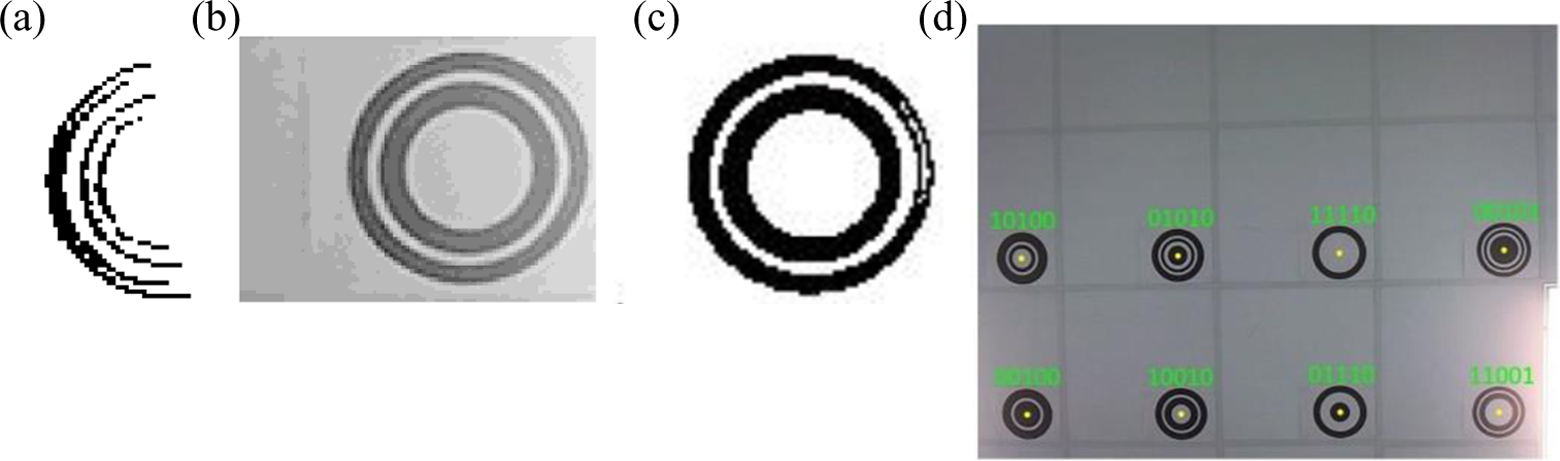
Local recognition example 1 ((a)–(c) show the process of recognizing landmark 11001 at the lower right corner of (d). (a) shows the result of global CLR extraction; (b) shows the result of DUCLR extension; (c) shows the result of local image clustering; (d) shows the final result of landmark recognition.)

Local recognition example 2 ((a)–(c) show the process of recognizing landmark 11010 in (d). (a) shows the result of global CLR extraction; (b) shows the result of DUCLR extension; (c) shows the result of local image clustering; (d) shows the final result of landmark recognition.)
CLR extraction
The contained CLR is extracted from each binary image piece of DUCLR using the same method of CLR extraction in the global recognition process.
Landmark identification
A CLR away from the image boundary, which contains a complete landmark, is identified using the template-matching method in the global recognition process. To identify a CLR on the image boundary, the CLR will be scaled according to the ratio between the size of ICLRs and that of templates, and all the templates will be cut on the same side according to the scaled CLR. To ensure the reliability of identification, we only process CLRs with less than half incompleteness. Then, the CLR is identified using the template-matching method.
For an identified landmark, the position of its center in the image is calculated as

where u and v denote the horizontal and vertical pixel coordinates of the landmark center, u′ and v′ are the horizontal and vertical pixel coordinates of the CLR center, sv and su are the width of the missing part, and ± corresponds to on which side of the CLR the missing part is located, with + associated with the right and bottom sides and − with the left and top sides.
Camera localization
Upon the recognition of landmarks, the global positions of the identified landmarks can be retrieved from the landmark map of the associated environment. Then, the position and orientation of the camera in the landmark environment can be estimated, which are equivalent to those of the mobile robot due to the fixed spatial relationship between the mobile robot and onboard camera. Algorithms are available to localize the camera based on the coordinates of landmarks in both the environmental and camera frames, for example, trilateration and triangulation. Localization algorithm is not an emphasis of discussion in this article. We adopt a convenient localization method to close the loop of this work.
Estimation of orientation and position
A typical indoor environment has a flat ground and a flat ceiling which are parallel to each other, the landmarks are attached to the ceiling, and the camera on the mobile robot faces the ceiling. We define the environmental frame as a Cartesian coordinate system with the origin fixed on the ceiling and XY plane coplanar with the ceiling. Thus, the image plane UV is parallel to the XY plane of the environmental frame (Figure 10).

Relationship between the image and environmental frames (O denotes the optical center of the camera, UV denotes the image plane, XY denotes the ceiling plane, C denotes the principal point on the image plane, A′ and B′ are landmarks on the ceiling, and A and B denote the projections of A′ and B′ on the image plane.)
Based on the difference between the orientation of a line in UV and that of the same line in XY, the orientation angle of the camera in XY can be estimated as

where xi and yi denote the environmental coordinates of the ith landmark in the units of physical length, ui and vi denote the image coordinates of the ith landmark in the units of pixels, and n denotes the number of identified landmarks. The first arctan in equation (6) gives the orientation angle of the line connecting two landmarks in XY plane, while the second arctan gives the orientation angle of the projection of the same line in UV plane. Equation (6) indicates that (1) at least two identified landmarks are needed to determine the planar orientation of the camera; and (2) if more landmarks are identified, the orientation estimation error can be reduced by averaging the estimates from multiple pairs of landmarks.
Then, by comparing the offset of a landmark relative to the optical center and the position of the same landmark in the environmental frame, the position of the camera in the environmental frame can be estimated as
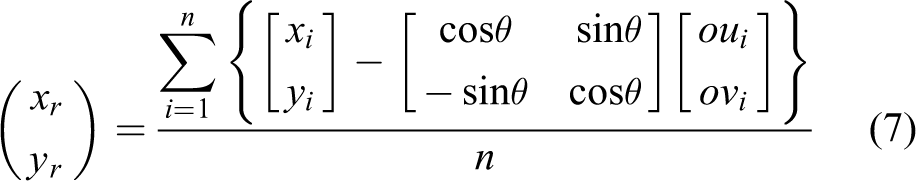
where, defined in the environmental frame in the units of physical length, xr and yr denote the XY coordinates of the optical center, oui and ovi denote the offsets of the ith landmark relative to the optical center in U and V directions, xi and yi denote the XY coordinates of the ith landmark, and θ denotes the orientation of the camera estimated using equation (6). Equation (7) reduces the position estimation error by averaging the estimates from multiple landmarks.
Mapping between pixels and physical length
The offsets of a landmark relative to the optical center, oui and ovi , are determined according to the mapping between the pixels in UV (image) plane and the physical length in XY (ceiling) plane. Two offset maps, U offset map and V offset map, are defined. Each map is a 2-D matrix which maps the U (or V) image coordinate of each pixel (in the units of pixels) to the physical offset of the corresponding point on the ceiling relative to the optical axis in the U (or V) direction (in the units of physical length). With these two offset maps, the offsets of any point on the ceiling (captured by the image) relative to the optical axis can be retrieved in U and V directions.
These two offset maps are generated from the following process. First, we place a mobile robot with an onboard camera facing the ceiling at a designated position on the ground, mount a number of markers on the ceiling at known positions within the field of view of the camera, and use the camera to take an image of the markers. Second, we retrieve the pixel positions of those markers in the image, obtain the physical offsets of those markers relative to the optical axis from their positions in the environmental frame, and define the U and V offset mapping at the pixels corresponding to those markers. Third, to define the U and V offset mapping at other pixels on the image plane, we create a triangular mesh to cover the whole image plane using Delaunay triangulation 37 where the pixel positions of those markers are used as the vertices, represent the position of each pixel using barycentric coordinates 38 as

and estimate the U and V offset mapping of each pixel by

where (up , vp ), (u 1, v 1), (u 2, v 2) and (u 3, v 3) denote the image coordinates of a pixel and the three vertices of the Delaunay triangle containing the pixel respectively, (oup , ovp ), (ou 1, ov 1), (ou 2, ov 2) and (ou 3, ov 3) denote the physical offset of these points relative to the optical center in U and V directions respectively, and λ 1 and λ 2 are the transformation coefficients from Cartesian coordinates to barycentric coordinates for pixel (up , vp ). To estimate the U and V offset mapping of each pixel, we at first calculate λ 1 and λ 2 from equation (8) based on known (up , vp ), (u 1, v 1), (u 2, v 2) and (u 3, v 3), and then calculate (oup , ovp ) using equation (9) based on known λ 1, λ 2, (ou 1, ov 1), (ou 2, ov 2) and (ou 3, ov 3).
Experiments
Experiments were performed to validate the proposed localization technique.
Experimental settings
The experimental environment was the indoor corridor environment of an office building (Figure 1), with a flat ceiling and a flat floor parallel to each other. A set of 5-bit landmarks were attached to the ceiling and facing the floor. Each landmark was printed with a diameter of 210 mm on a piece of letter-sized regular print paper. The distance between the centers of neighboring landmarks was 610 mm. The positions of the landmarks in the environmental frame were measured manually and carefully.
A Pioneer 3-DX mobile robot was used as the carrier (Figure 1). A Logitech HD Pro C910 webcam (with a resolution of 640 × 480 pixels) was mounted on the top of the robot and faced upward to capture the landmarks attached to the ceiling. The distance between the onboard camera and the ceiling is about 1870 mm. An onboard laptop computer, with Intel Core 2 Due 2.0 GHz CPU and 2G RAM, was used to control the movement of the mobile robot, receive and process the images from the camera, and estimate the camera’s position and orientation.
The landmarks were arranged into three different grids (Figure 11), and the proposed mobile robot localization scheme was tested with three types of robot paths, linear, rectangular and circular. In Figure 11, the landmarks are labeled with decimal identities converted from the original binary identities for a compact presentation.

Landmark arrangements and robot paths in experiments.
The camera was calibrated before the experiments to obtain the intrinsic camera parameters needed for image dedistortion and localization, using a printed black/white checkerboard pattern and the camera calibration toolbox in the literature. 34 The calibration results are listed in Table 1.
Calibrated camera parameters.

Experimental results
The experiments were carried out with the above settings. Figure 12 presents the landmark recognition results of two typical cases. Figures 3 and 12 show that various objects in the environment other than landmarks were captured by the input images, including ceiling tiles, light, AC outlet, alarm, exit sign, and electrical box. The results in Figures 8(d), 9(d), and 12 show that the proposed landmark design and recognition scheme lead to effective landmark recognition under the disturbance of the illumination condition, incompleteness of landmarks, and existence of other objects.

Landmark recognition results under the disturbance of illumination, incomplete landmarks, and nearby objects.
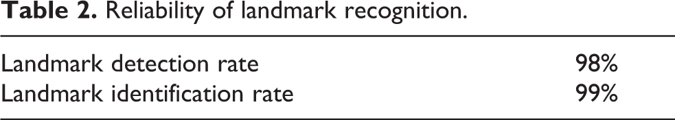
The reliability of landmark recognition was tested with the landmark arrangements and robot paths in Figure 11. The overall reliabilities of landmark detection and identification are shown in Table 2. The detection rate is the ratio between the number of landmarks detected and the total number of landmarks captured by the camera. The identification rate is the ratio between the number of landmarks correctly identified and the number of landmarks detected. Those landmarks with more than half incompleteness are not included. The results show a very high reliability of landmark recognition.
Reliability of landmark recognition.
Moreover, the test results of localization accuracy are presented in Table 3. The position was measured at a precision of 1 mm, while the orientation was measured at a precision of 1 degree. Consequently, with the experimental system, the overall average position accuracy was 20.2 mm, and the overall average orientation accuracy was 0.5°, which are sufficient for most regular-scale indoor mobile robot tasks. These position and orientation errors are system-specific. The landmark recognition process reliably identified the landmarks and thus did not contribute to the localization errors. The main factors causing these errors include the landmark environmental position error, landmark image position error, image-physical offset mapping error, camera calibration error, and camera resolution. Hence, the localization accuracy is expected to improve as the accuracies in measurement and camera improve.
Localization accuracy.

In addition, with the computation power of the experimental system, the time of the whole localization process from the image input to the localization estimation ranges from 0.30 s to 0.36 s, depending on the necessity of running the local recognition process. In particular, the global recognition process for the whole image takes about 0.25 s, the local recognition process for each DUCLR takes about 0.10 s, and the localization estimation takes about 0.001 s.
Conclusion and discussion
This article presents a landmark-based self-localization scheme for indoor operations of mobile robots. The proposed binary ring-code landmark design and bilayer landmark recognition process are robust to environmental illumination conditions and substantial landmark incompleteness in images. The experimental results have proved that the proposed scheme is highly reliable in landmark detection and identification. The presented localization scheme can work with independent mobile robots and multi-robot systems with consistent performance.
The work of this article focuses on landmark recognition and landmark-based localization. However, the localization accuracy may be further improved by fusing the localization results of this approach with those of other onboard localization approaches. For instance, off-the-shelf mobile platforms often come with onboard odometry based on wheel encoders. Although both the landmark-based localization and odometry have inaccuracy, by fusing the localization results from both approaches using a fusion algorithm, for example, extended Kalman filtering, 39 the uncertainty in localization can be reduced to be lower than that of each individual localization approach, and thus, the localization accuracy can be improved. Moreover, the landmark-based approach may be further strengthened by incorporating more visual features extracted from images. 40
A practical consideration for applying landmark-based localization is to balance between the number of landmarks used in an environment and the area covered. A larger environment needs a larger number of landmarks. If we would use a set of landmarks with unique identities, we would have to increase the number of bits in the identity coding. In order to maintain the detectability of landmarks with more rings under the limited camera resolution, we would need to increase the size of the landmark pattern. Large number and large size of landmarks are not desirable from the point of view of landmark installation/maintenance and space usage. We envision the possibility of covering a large environment with a relatively small set of landmarks. The presented localization algorithm requires only two identified landmarks to localize the camera each time. Thus, we can explore a relatively sparse landmark arrangement for the environment, so that a limited number of landmarks can cover a larger area. Moreover, a large environment can be divided into subareas each of which can be covered by a small set of landmarks. A robot can self-localize inside a subarea based on landmarks, and self-localize in the whole environment by adding its location inside the current subarea to the subarea’s location in the whole environment. In this way, we can reuse a small set of landmarks to all those subareas. Another possibility is to use the landmark-based localization together with other onboard localization approaches, for example, odometry. Whenever landmarks are detected, the robot will self-localize using the landmark-based localization approach. During the interval between successive landmark detections, the robot will self-localize using odometry. The landmark-based localization does not have error accumulation and thus plays a role of preventing error accumulation and correcting odometry. These strategies may be combined to deal with large environments.
A main task of our further research is to improve the flexibility of camera and landmark arrangement. It is well recognized that attaching landmarks to the ceiling provides more tolerance to obstacles than other layouts. However, it also constrains the camera to face the ceiling. Considering that camera is a capable sensor for mobile robot navigation, it is not economic to limit its function to localization only. Instead, it is more natural to self-localize while the camera is observing the environment. Therefore, the camera can be oriented for observation instead of localization. To achieve that, we will need to deal with some new challenges: Landmarks are attached to generic planes, not limited to the ceiling; the images of landmarks are deformed in general, not circular; the sizes of landmark projections generally vary. Moreover, larger number and more variety of objects other than landmarks may be captured by a camera oriented in a generic direction than facing the ceiling. Avoidance/minimization of the false detection of landmarks in such a situation will be an important research objective. Besides ensuring reliable landmark recognition, we will seek to improve the processing speed of landmark recognition in order to make the landmark-based localization scheme sufficient for mobile robot applications with higher requirement in speed.
Footnotes
Declaration of conflicting interests
The author(s) declared no potential conflicts of interest with respect to the research, authorship, and/or publication of this article.
Funding
The author(s) disclosed receipt of the following financial support for the research, authorship, and/or publication of this article: This work was supported in part by National Science Foundation (Award no. 1360873).