
Abstract
This paper presents the design, implementation, and experimental validation of a compact Ackermann-steered mobile robot platform developed for autonomous navigation and diverse service applications. The platform integrates dual stereo cameras and an inertial measurement unit to ensure robust localization, alongside a pan-tilt RGB-D camera designed for active perception tasks. Specifically, the dual stereo cameras mounted at the front and rear provide bidirectional visual odometry, which is fused with inertial measurements via an extended Kalman filter to achieve accurate, drift-reduced state estimation. Furthermore, the pan-tilt actuator enables dynamic viewpoint control, facilitating robust object tracking and dense three-dimensional (3D) perception. The system is built upon the Robot Operating System 2 framework, providing a modular and extensible architecture that allows for seamless integration with various perception and navigation algorithms. Experimental evaluations—including velocity tracking, dual visual odometry benchmarking, mapless navigation, and real-time 3D mapping—validate the effectiveness and versatility of the proposed platform in outdoor environments.
Introduction
Mobile robots have been widely adopted across domains such as delivery, infrastructure inspection, and environmental monitoring.1–3 As the demand for compact, cost-effective, and adaptable robotic platforms continues to grow, recent research has focused on developing systems capable of robust navigation and enhanced situational awareness, particularly in global positioning system (GPS)-denied or complex outdoor environments.4–6
Among various locomotion schemes, Ackermann steering mechanisms are particularly advantageous in outdoor paved settings due to their low-slip motion, mechanical simplicity, and compatibility with car-like kinematic constraints. However, navigation in such environments often faces challenges when Global Navigation Satellite System (GNSS) signals are unreliable or unavailable. This necessitates advanced onboard perception and localization strategies capable of operating independently of external infrastructure.
To address these limitations, we propose a compact and versatile Ackermann-steered mobile robot platform featuring stereo vision-based visual odometry (VO), inertial sensing, and active perception modules. The system employs front and rear stereo cameras to estimate bidirectional VO, which is fused with inertial measurement unit (IMU) data via an extended Kalman filter (EKF) to achieve drift-compensated localization. This approach enhances robustness in visually degraded or occluded environments by ensuring consistent pose estimation during bidirectional maneuvers. Furthermore, a pan-tilt RGB-D camera provides active three-dimensional (3D) perception, enabling the platform to serve as a testbed for dynamic visual tracking algorithms.
Built upon the Robot Operating System 2 (ROS 2) framework, the platform offers a modular and extensible software architecture for perception, planning, and control. 7 While a complete end-to-end software stack is provided, individual modules are designed for compatibility with standard ROS 2 packages, facilitating the flexible integration and evaluation of various algorithms. This design ensures the platform functions effectively both as a standalone system and as a research testbed for benchmarking diverse perception and navigation strategies.
This paper outlines the hardware and software architecture of the platform and validates its performance through experiments on velocity control, dual VO-based localization, mapless navigation, and 3D mapping. The experimental results confirm the system’s effectiveness and versatility, demonstrating its suitability for research and outdoor service applications, including autonomous driving, inspection, and patrol missions.
Related work
Mobile robotic platforms utilize diverse drivetrain configurations, each tailored to specific mobility requirements and operational environments. This section categorizes prior research based on drivetrain mechanisms—specifically differential drive, skid steering, and omnidirectional systems—and examines their system characteristics. Subsequently, we highlight the limitations of existing platforms in outdoor service scenarios and contrast them with the proposed Ackermann-steered platform, which features high-performance computing, dual VO, and active perception capabilities.
Differential drive and skid steering platforms
Differential drive and skid steering mechanisms are widely adopted in mobile robotic platforms due to their mechanical simplicity, compact form factor, and ease of control. These configurations are particularly advantageous for cost-sensitive applications and are prevalent in service robots, educational kits, and research prototypes.
In practical deployments, skid-steered platforms have demonstrated efficacy in ground-surface exploration, spraying, and agricultural tasks. For instance, the Warthog platform by Clearpath Robotics was customized to support both ground and subsurface imaging through the integration of LiDAR and microwave antennas, validating its field readiness in both real-world and simulated experiments. 8 Similarly, platforms equipped with pan-tilt actuators and magnetic guidance systems have been developed specifically for greenhouse spraying applications. 9
Conversely, differential drive systems have been extensively employed in research and educational settings. Their low mechanical complexity and modular design make them well-suited for algorithm validation and control education. The UiAbot platform exemplifies this trend by integrating LiDAR and an IMU within a ROS 2-based control architecture, enabling simultaneous localization and mapping (SLAM) and autonomous navigation in indoor environments. 10 Another compact differential drive platform has been introduced as a flexible testbed for research-level control and autonomy experiments. 7
Despite their widespread utility, these platforms possess inherent kinematic limitations. Both differential drive and skid steering systems are prone to significant wheel slippage, which degrades odometry accuracy and results in trajectory deviations. Furthermore, generalizing their motion models across diverse terrains remains challenging, limiting their performance in unstructured or inclined environments.
Omnidirectional platforms
Omnidirectional mobile robots, typically employing Mecanum or omni wheels, offer holonomic mobility characterized by independent translation and rotation capabilities. This maneuverability renders them particularly advantageous in constrained indoor environments, such as smart factories and logistics warehouses, where precise movement within tight spaces is essential. Consequently, numerous studies have leveraged this mobility to facilitate autonomous navigation, manipulation, and human–robot interaction (HRI) tasks.
In industrial contexts, omnidirectional platforms have been engineered with modular drive-suspension units to accommodate variable payloads while ensuring agile motion.11,12 To support robust navigation in cluttered spaces, these systems frequently employ multi-sensor fusion, integrating LiDAR, IMU, and VO to achieve accurate localization. 13 Furthermore, lightweight onboard computing units running ROS 2 have been widely adopted to enable real-time SLAM and autonomous control. 14 Beyond autonomous operations, such platforms are also utilized in HRI scenarios; for instance, variable-admittance models have been applied to decouple compliant behavior in intended and unintended motion directions, thereby ensuring intuitive and safe collaboration with human operators. 15
While omnidirectional mobility provides distinct benefits in structured indoor settings, these advantages often come at the cost of mechanical robustness and traction efficiency. Due to the complexity of the wheel mechanisms and reduced stability on uneven surfaces, such platforms are generally less suitable for high-speed or outdoor operations compared to conventional steering configurations.
Swerve-drive and swivel-based platforms
Swerve-drive platforms enable holonomic motion by independently controlling the steering and propulsion of each wheel module, providing superior maneuverability for precise navigation in dense or dynamic environments. Consequently, numerous swerve and swivel-based architectures have been proposed as effective solutions to achieve agile planar motion.
For instance, the RoMop platform employs a swivel-based mechanism that facilitates multidirectional translation through continuous platform rotation and passive planar linkages, thereby mitigating kinematic singularities. 16 Similarly, the S-bot utilizes a solar-powered, remotely actuated swerve-drive system designed to support agile, long-range transport tasks in outdoor logistics environments. 17
Research on three-wheeled swerve platforms has demonstrated high-speed trajectory tracking using spline-based motion planning, achieving reduced wheel slip and lower position errors compared to omni-wheel systems.18,19 Furthermore, holonomic platforms based on powered casters, such as TidyBot++, have been developed to enhance mobility in household settings, enabling learning-based manipulation through intuitive tele-operation. 20
However, despite their mechanical versatility, swerve-drive systems typically necessitate multiple actuators per wheel and require sophisticated multi-level control architectures. This inherent complexity increases hardware costs, computational loads, and energy consumption. Moreover, ensuring precise synchronization between wheel steering and propulsion poses significant challenges for real-time control, particularly under dynamic conditions or on uneven terrain. These factors often constrain their practicality for low-cost, long-duration, or power-limited applications.
Ackermann-steered platforms
Ackermann steering geometry is extensively utilized in autonomous ground vehicles due to its kinematic efficiency and suitability for high-speed, low-slip motion on structured surfaces. Unlike omnidirectional or skid-steered mechanisms, Ackermann geometry minimizes tire scrub and facilitates smoother turning dynamics, making it well-suited for applications demanding precise maneuvering and energy efficiency.
Significant research has been dedicated to trajectory planning and control strategies tailored to the non-holonomic constraints of Ackermann-steered robots. For power-constrained applications such as planetary exploration and border patrol, energy-aware path planning approaches have been proposed, achieving notable energy savings through motion primitives consistent with Ackermann kinematics. 21 In agricultural contexts, ROS-based navigation stacks combining real-time trajectory optimization with non-smooth pose regulation have demonstrated robust obstacle avoidance. 22 Additionally, for off-road scenarios, trajectory planning frameworks incorporating terrain traversability and 3D pose dynamics have been introduced to ensure feasible path generation on uneven terrain. 23
Parallel efforts have focused on platform development and advanced control methodologies. The Chronos platform, for instance, offers a cost-effective, 1/28-scale testbed for education and research, featuring an open-source software framework for multi-agent coordination. 24 To address the complexities of rough-terrain path tracking, hybrid controllers leveraging deep reinforcement learning have been developed, exhibiting enhanced robustness against dynamic disturbances compared to traditional model-based control. 25 Furthermore, real-time planners utilizing motion primitives have enabled smooth, time-efficient trajectories for operation amidst moving obstacles, 26 while time-optimal trajectory generation has been analyzed to identify fundamental components for efficient navigation under strict dynamic constraints. 27
Despite these advancements, a significant gap remains in standalone autonomy. Most existing Ackermann-based platforms rely heavily on pre-mapped environments or external positioning systems, such as GNSS or motion capture, due to a lack of robust onboard state estimation capabilities. Where VO is employed, it is frequently limited to monocular setups, which are susceptible to scale ambiguity and failure in low-texture environments. Moreover, current platforms seldom incorporate active perception modules, such as pan-tilt RGB-D sensors, limiting their capacity for dynamic object tracking and semantic scene understanding.
Distinctiveness of the proposed platform
The proposed platform integrates an Ackermann steering mechanism with dual stereo vision and visual–inertial fusion to achieve accurate, drift-reduced state estimation and dense 3D perception in real time. The Ackermann configuration ensures efficient, low-slip maneuverability while mimicking the kinematic characteristics of on-road vehicles, offering superior suitability for realistic navigation scenarios compared to differential or skid-steered systems.
For robust localization, dual stereo cameras mounted at the front and rear provide bidirectional VO. These estimates are fused with angular velocity data from an onboard IMU via an EKF, substantially mitigating the drift typically observed in VO-only systems, particularly in environments with occlusions or low-texture regions. Furthermore, the platform incorporates a pan-tilt RGB-D camera to enable active object tracking with dynamic viewpoint control. This capability ensures continuous perception of moving or partially occluded targets in 3D space. Unlike conventional LiDAR-based systems, our approach performs dense 3D mapping using stereo image sensing. This enables the generation of color-textured maps without reliance on heavy or expensive LiDAR sensors, offering a lightweight and cost-effective alternative while preserving map density and spatial fidelity.
The system architecture is fully modular and implemented in ROS 2, supporting real-time SLAM with loop closure, active perception, and autonomous navigation. This design renders the platform not only a practical solution for outdoor service tasks such as patrol, inspection, and delivery but also a flexible and extensible testbed for mobile robotics research.
To provide a clear positioning of the proposed system within the landscape of existing research, Table 1 presents a comparative analysis with other representative Ackermann-steered mobile robot platforms: the miniature educational robot Chronos, 24 the open-source autonomous racing platform F1TENTH, 28 and the mid-sized off-road platform AgileX Hunter SE. 25 While Chronos offers a cost-effective solution for swarm robotics, it relies on external infrastructure for localization. Similarly, the F1TENTH platform, widely used for high-speed racing research, typically employs 2D LiDAR and standard computing units such as the Jetson TX2 or Xavier. However, it generally relies on fixed sensor mounts, limiting its ability to perform active perception tasks. The Hunter SE represents a robust solution for rough terrain but employs a heavy sensor suite including GNSS, making it less suitable for compact service applications in GPS-denied environments. In contrast, our platform is distinguished by integrating high-performance onboard computing (NVIDIA Jetson AGX Orin) and a dual stereo vision system into a compact chassis. Unlike F1TENTH or Hunter SE, our system achieves robust drift-reduced localization via fused dual VO without reliance on LiDAR or GNSS, and uniquely supports active object tracking through its pan-tilt perception module.
Comparison of the proposed platform with existing Ackermann-steered research platforms.

IMU: inertial measurement unit; 2D: two-dimensional; SLAM: simultaneous localization and mapping; GNSS: global navigation satellite system; VO: visual odometry.
Hardware design
Platform overview
Figure 1 presents an overview of the developed robotic platform. The robot measures
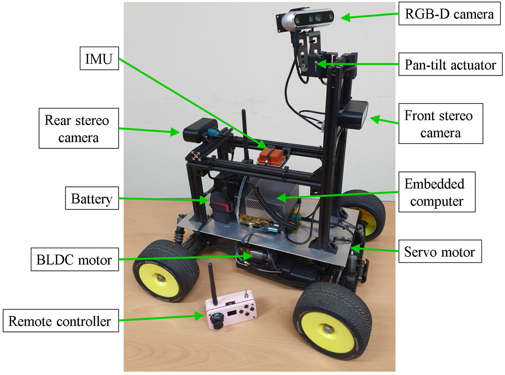
Overview of the physical configuration of the robotic platform.
Hardware architecture
Figure 2 illustrates the hardware architecture and system interfaces. The central onboard computer (NVIDIA Jetson AGX Orin) operates on the ROS 2 framework and orchestrates communication between the sensing and control modules. It executes high-level computational tasks, including object detection and tracking, 3D mapping, sensor-fusion-based localization, path planning, and motion command generation.
The propulsion system is powered by a brushless direct-current (BLDC) motor (Hobbywing XERUN 4268) driven by an electronic speed controller (ESC; Hobbywing XERUN XR8). Steering is actuated by a high-torque servo motor (Savox SB-2290SG) via pulse width modulation (PWM) signals. A 32-bit microcontroller (Arduino Nano ESP32) handles low-level control, receiving velocity and steering commands from the onboard computer via a universal serial bus (USB) serial interface or from a remote controller via Zigbee wireless communication. The microcontroller translates these inputs into PWM signals for the ESC and servo motor, simultaneously executing proportional–derivative (PD) control to regulate the BLDC motor speed.

Block diagram of the hardware architecture. Solid arrows indicate wired connections, and the dotted arrow represents wireless communication.
For perception, the platform is equipped with an RGB-D camera (Intel RealSense D455) dedicated to object tracking and two stereo cameras (StereoLabs ZED X Mini) mounted at the front and rear of the chassis for VO and 3D perception. The stereo cameras interface with the onboard computer via Gigabit Multimedia Serial Link connections to ensure high-bandwidth data transmission, while the RGB-D camera connects via USB.
To facilitate active tracking, the RGB-D camera is mounted on a two-axis pan-tilt actuator (ROBOTIS Dynamixel 2XL430-W250), providing dynamic gaze control. Additionally, an IMU supplies inertial measurements, which the onboard computer uses to estimate the robot’s angular velocity and orientation. Both the pan-tilt actuator and the IMU communicate with the onboard computer via USB.
Software design
Software architecture
Figure 3 presents the software architecture of the proposed robotic platform. The system is built upon the ROS 2 framework, which ensures modularity, distributed communication, and real-time performance. Each block in the diagram represents either an individual ROS 2 node or a logical cluster of nodes collaborating to execute specific robotic functions.
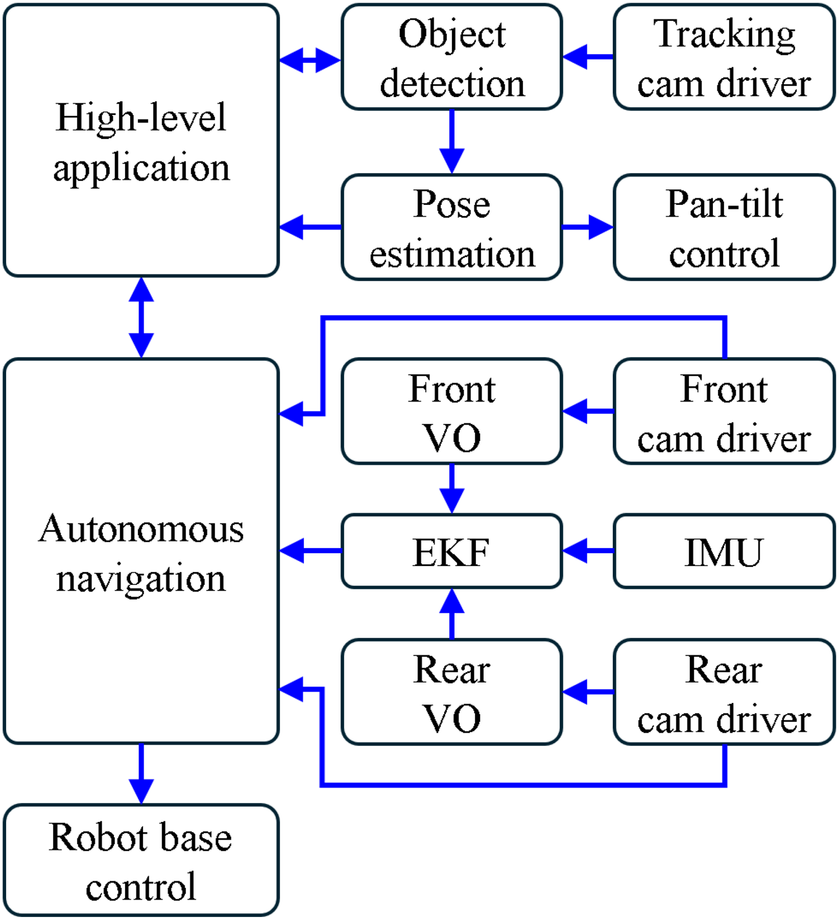
Software architecture of the robotic platform.
At the highest level, the High-Level Application Module orchestrates task-specific behaviors tailored to the operational requirements. This module serves as the command interface for mission-level applications, such as last-mile delivery, autonomous patrolling, and infrastructure inspection. It transmits navigation goals to the Autonomous Navigation Module while receiving real-time feedback regarding the robot’s pose, system status, and task progress.
The Autonomous Navigation Module is implemented using the Nav2 stack, 29 leveraging its comprehensive suite of algorithms for path planning and control. In this platform, the module integrates subcomponents for localization, costmap generation, global and local planning, and recovery behaviors to facilitate robust point-to-point navigation and dynamic obstacle avoidance. Based on sensor inputs and goal constraints, it computes the desired linear velocity and steering angle. These commands are transmitted to the Robot Base Control Module, which translates them into PWM signals to actuate the ESC and steering servo motor.
To support active perception capabilities, the platform incorporates a vision-based tracking subsystem. The Tracking Cam Driver Module acquires RGB-D images and point clouds from the pan-tilt camera, which are subsequently processed by the Object Detection Module to identify target objects. The Pose Estimation Module calculates the 3D position of the detected target, while the Pan-Tilt Control Module actively regulates the two-degree-of-freedom gimbal. This feedback loop ensures continuous visual alignment with the target, even during robot motion.
For state estimation, the system employs two stereo vision modules mounted at the front and rear of the chassis. The Front and Rear Cam Driver Modules capture synchronized stereo image pairs and depth information. These data are processed by the respective VO Modules to estimate the egomotion of each camera relative to its initial frame. Finally, the EKF Module fuses these VO estimates with angular velocity data from the IMU to produce a drift-reduced, consistent estimate of the robot’s pose and velocity.
The Autonomous Navigation Module utilizes this fused odometry for localization and aggregates point cloud data from both stereo cameras to construct costmaps for path planning. This architecture enables fully autonomous operation, integrating accurate localization, responsive navigation, and intelligent object tracking within a unified and extensible ROS 2 framework.
Odometry estimation
The EKF Module (see Figure 3) estimates the robot’s pose by fusing egomotion data from the Front and Rear VO Modules with angular velocity measurements from the IMU, thereby providing robust position and orientation estimates over time.
Each VO Module independently computes the six-degrees of freedom motion of its corresponding stereo camera by tracking visual features across consecutive frames. This stereo-based approach facilitates depth-aware 3D motion estimation by exploiting geometric disparities in the observed environment. Crucially, utilizing both front and rear stereo cameras significantly enhances robustness, particularly when one sensor’s field of view is compromised by occlusion, poor illumination, or low texture. By fusing the VO outputs from both sensors via the EKF, the system generates a highly accurate and drift-reduced odometry estimate relative to the robot base frame.
Figure 4 depicts the coordinate frames assigned to the robot chassis and the stereo cameras. The robot coordinate frame,
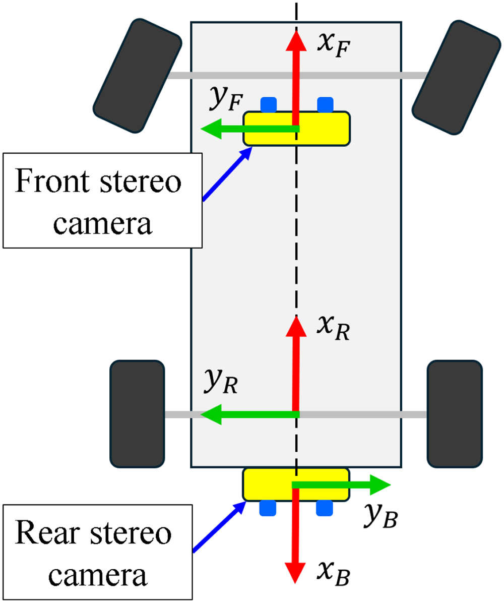
Coordinate frames of the robot platform and its stereo vision sensors.
The coordinate frames, velocity vectors, and transformation matrices utilized in this work are summarized in Table 2. These notations are consistently applied throughout the derivation of the state estimation and control models in the subsequent sections.
Nomenclature for coordinate frames, velocity vectors, and transformations.
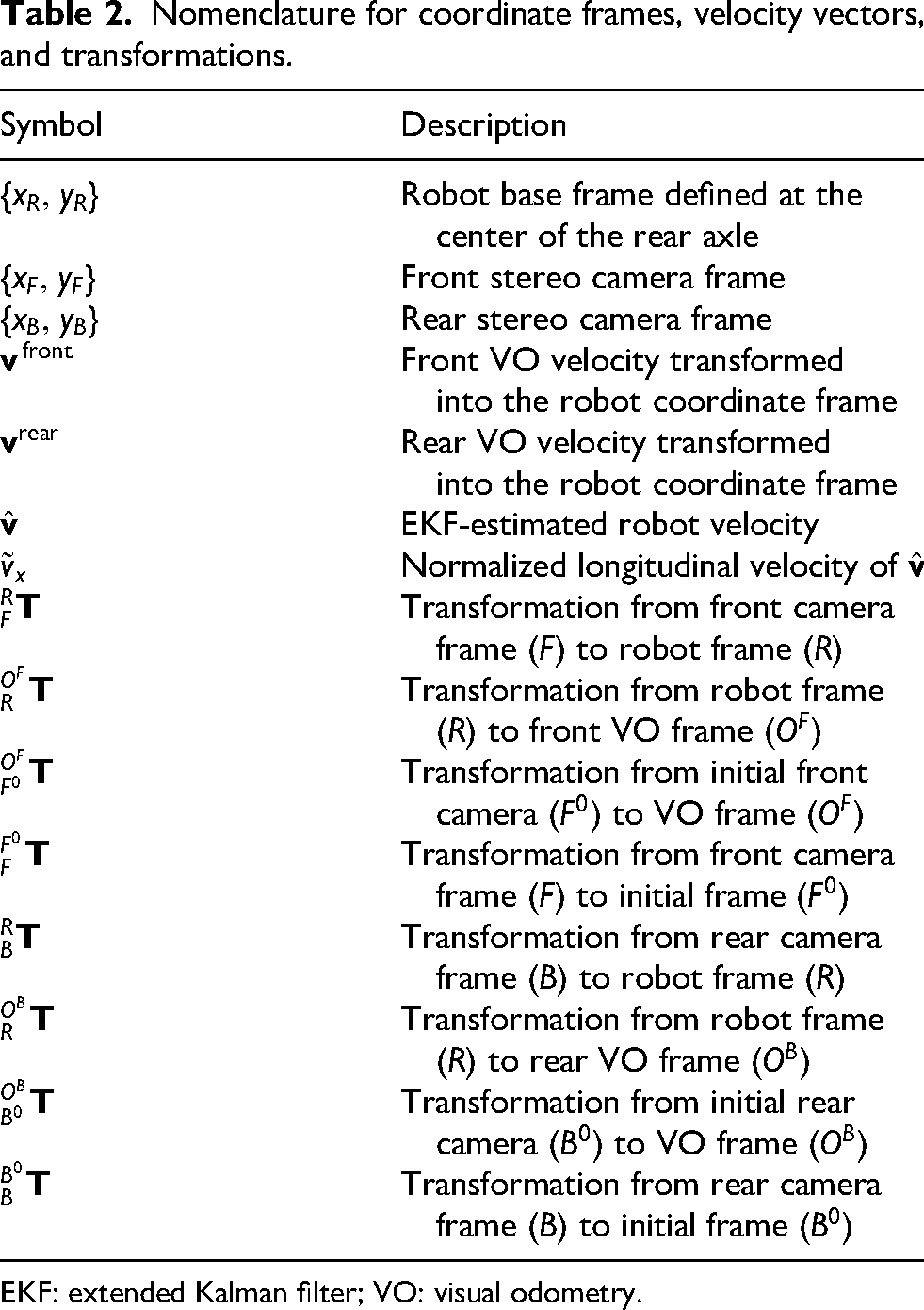
EKF: extended Kalman filter; VO: visual odometry.
VO filtering
VO is inherently susceptible to drift induced by environmental factors such as illumination variations, motion blur, dynamic obstacles, and texture-less surfaces. Directly incorporating these outlier-prone measurements into the EKF update step can severely compromise the integrity of the overall state estimation.
To mitigate this, a filtering mechanism is implemented to reject unreliable VO measurements based on the robot’s kinematic constraints and velocity feasibility. First, the velocity estimates 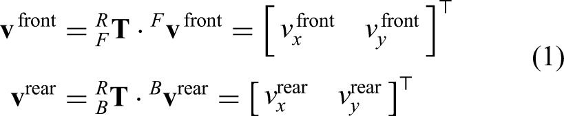
Figure 5 illustrates the admissible region in the velocity space defined for outlier rejection. Here,
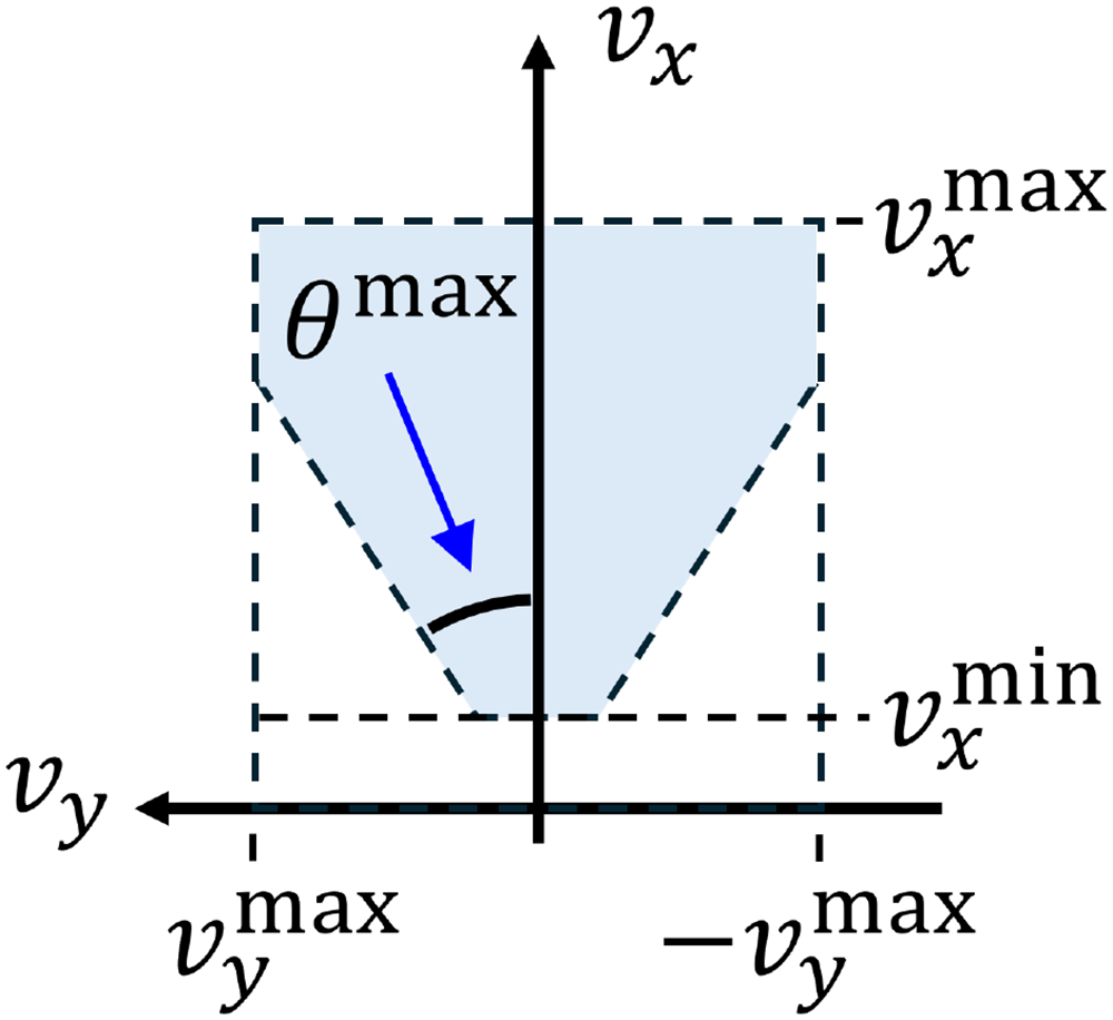
Admissible region in the velocity space employed for outlier rejection.
To ensure kinematic consistency, a VO measurement is accepted for the EKF update only if it falls within the defined validity bounds: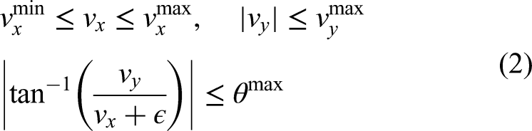
Coordinate transformation of VO estimates
The Front and Rear VO Modules independently compute the egomotion of their respective stereo cameras relative to their initial frames. To fuse these spatially disjoint estimates, the camera-centric trajectories must be mapped into the common robot base frame. This transformation ensures that all motion updates are consistent with the robot’s kinematic center, enabling accurate sensor fusion within the EKF.
Let 
where
An analogous transformation is applied to the rear VO system. Let 
where
By applying these transformations, the trajectories from both the front and rear cameras are unified into the robot base frame. These synchronized and spatially aligned pose estimates serve as redundant measurement inputs to the EKF, thereby enhancing the robustness and accuracy of the final localization.
Velocity control
The Robot Base Control Module translates high-level motion commands—specifically reference linear velocity and steering angle—into low-level actuator signals. While the steering angle is regulated by a servo motor with an internal closed-loop mechanism, precise linear velocity control necessitates a custom controller to generate appropriate PWM signals for the ESC. To achieve this, we employ a feedforward-feedback control architecture. A polynomial mapping function, derived from empirical data, generates the baseline feedforward PWM command for a desired reference velocity, while a PD controller utilizes real-time velocity feedback to compensate for modeling uncertainties and dynamic disturbances.
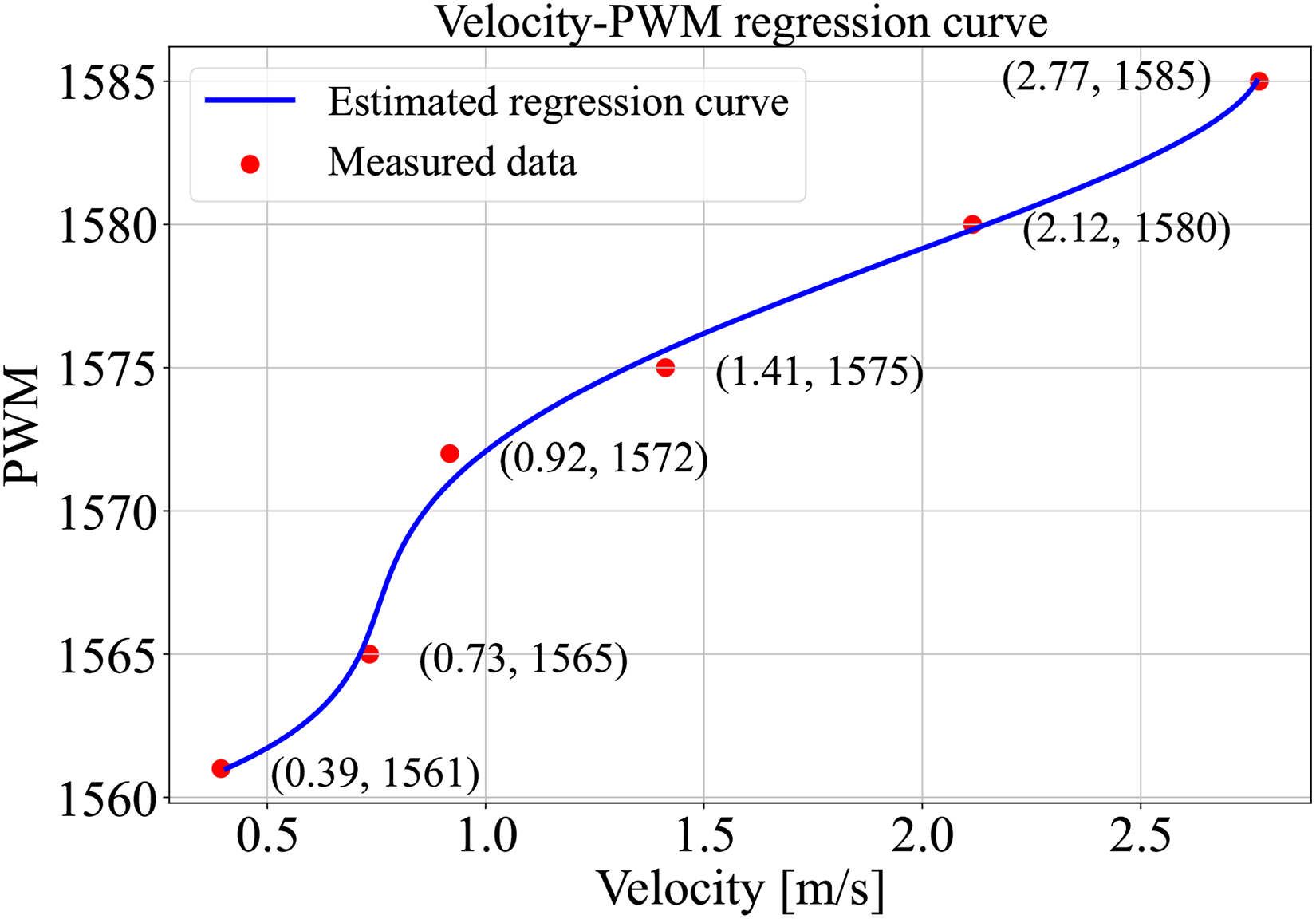
To characterize the system response and derive the feedforward model, open-loop step tests were conducted. Figure 6 depicts the measured forward velocity profiles for six discrete PWM inputs (1561, 1565, 1572, 1575, 1580, and 1585). The robot’s longitudinal velocity,
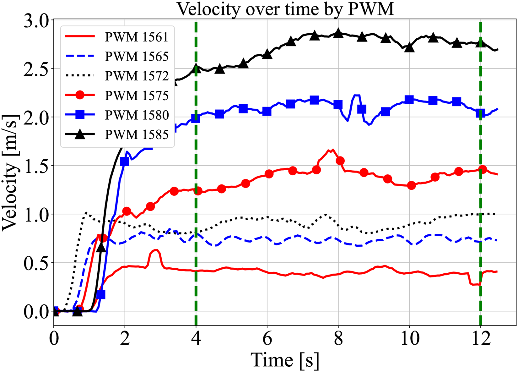
Measured forward velocities of the robot over time for six discrete pulse width modulation (PWM) inputs.
To facilitate robust regression across the full operational range, the collected 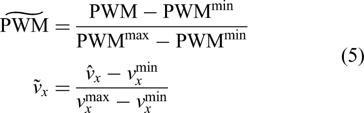
Parameters for pulse width modulation (PWM) and velocity normalization.

Using these normalized datasets, a fourth-order polynomial regression model was derived to approximate the mapping from the reference velocity 
Polynomial regression result between normalized forward velocity and normalized pulse width modulation (PWM) input.
Coefficients of the fourth-order polynomial regression model.

Experiment
Velocity tracking
To validate the efficacy of the proposed control strategy, we evaluated the robot’s tracking performance across a range of reference velocities. The control architecture integrates the feedforward model, derived from the fourth-order polynomial regression in (6), with a PD feedback controller to minimize tracking errors in real time.
Step response tests were conducted for reference velocities of 0.5, 1.0, 1.5, 2.0, and 2.5
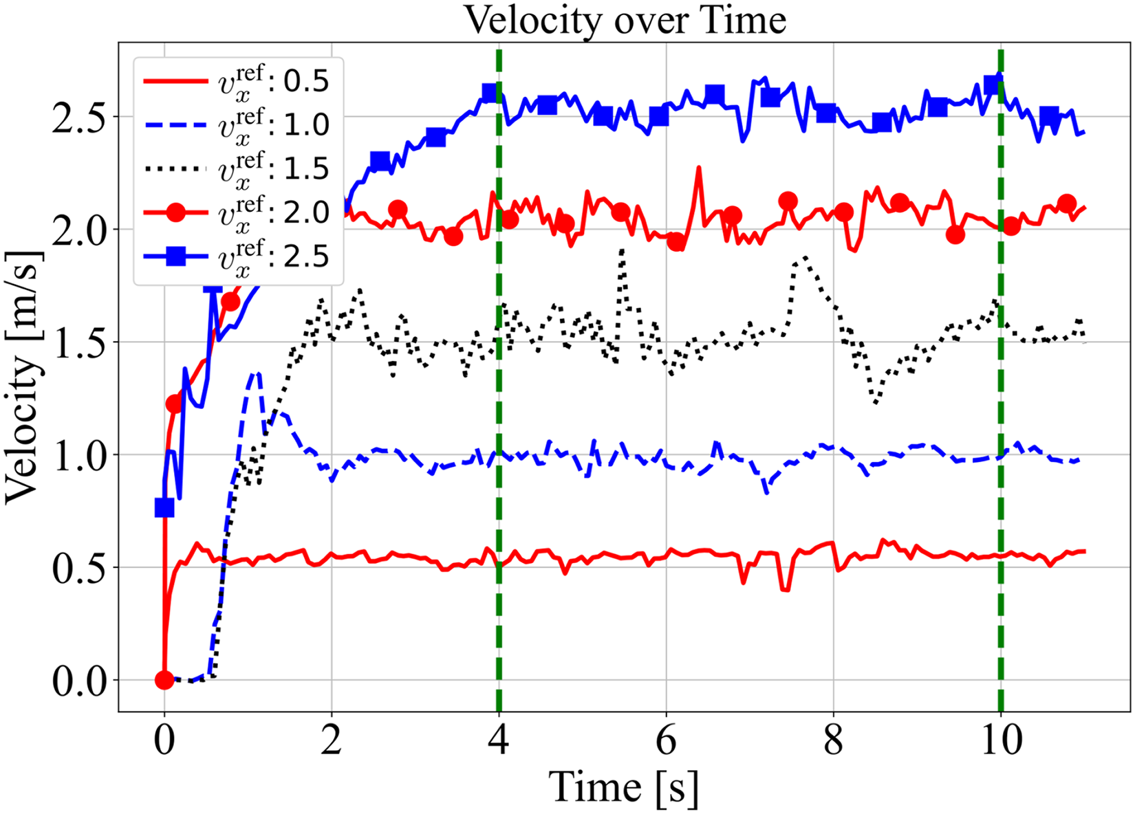
Measured velocities over time for five reference velocity commands.
Statistical analysis of velocity tracking performance (steady-state interval: 4–10 s).

RMSE: root mean square error; SD: standard deviation.
The quantitative results demonstrate robust tracking performance for most reference velocities, maintaining RMSE values generally below 0.085
However, a distinct increase in both RMSE (
Dual VO-based localization
To validate the contribution of the proposed dual VO system compared to single-camera configurations, we conducted a comparative ablation study in an outdoor environment. The experiment was designed to quantify the localization accuracy of the front-only VO, rear-only VO, and the proposed dual VO (fused via EKF) with respect to a ground truth trajectory obtained via real-time kinematic (RTK) GPS.
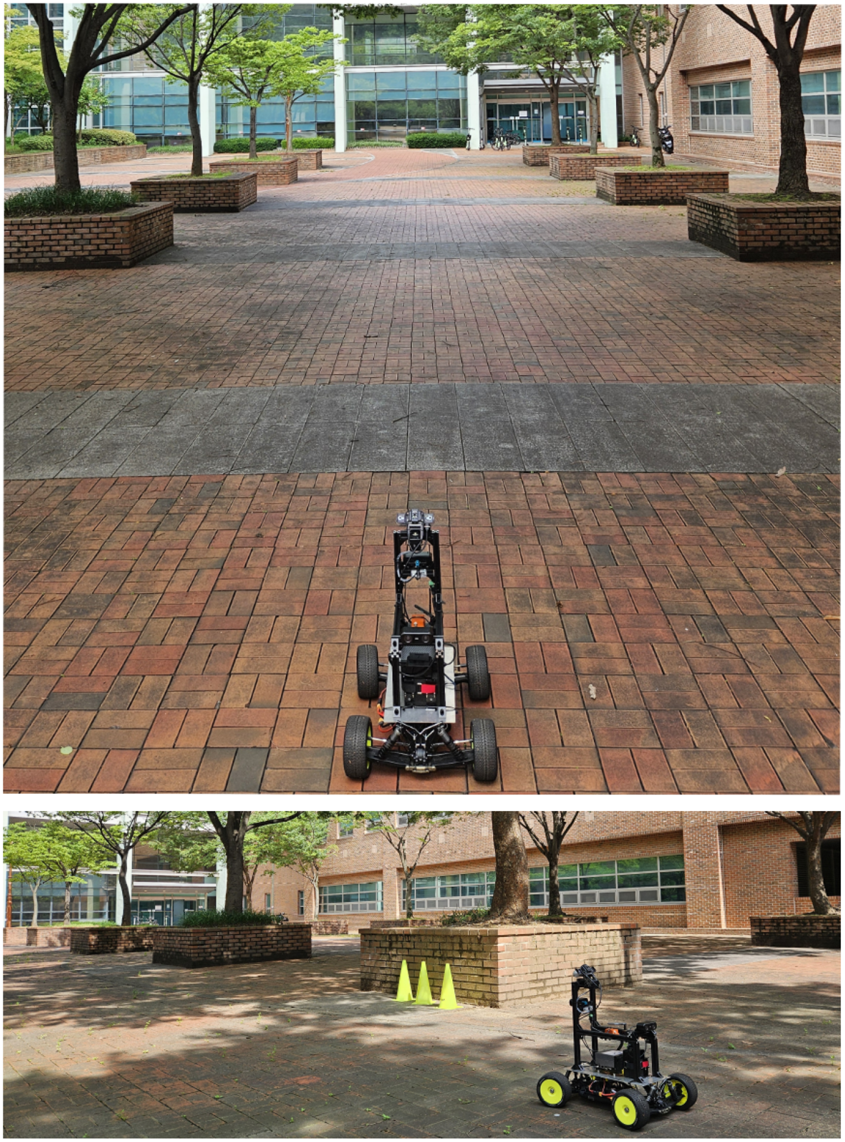
As illustrated in Figure 9, the experiment took place in a paved outdoor square. To introduce realistic environmental challenges, the test was conducted under uneven illumination conditions. As shown in the inset of Figure 9, the front camera faced intense backlighting and lens flare due to direct sunlight, whereas the rear camera observed a region cast in shadow. These conditions were intentionally selected to verify the robustness of the sensor fusion algorithm when individual visual sensors are degraded by lighting variations.
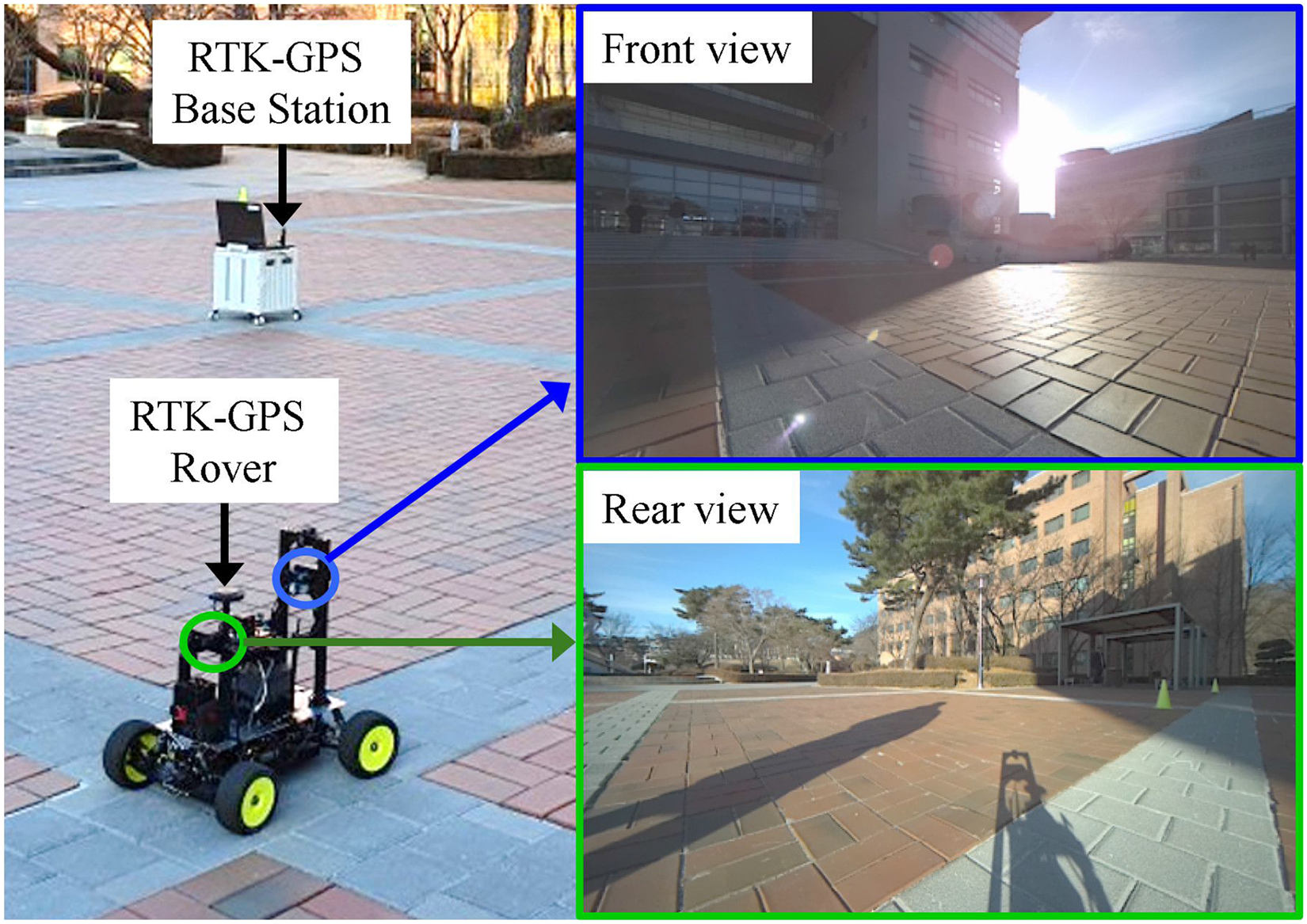
Experimental setup for evaluating visual odometry accuracy. An RTK–GPS system (Base Station and Rover) was employed to record the ground truth trajectory. The inset images demonstrate the contrasting illumination conditions: the Front view is affected by strong backlighting, while the Rear view captures shadowed regions. RTK: real-time kinematic; GPS: global positioning system.
The robot traversed a rectangular path, and the trajectories estimated by the front VO, rear VO, and dual VO were recorded simultaneously alongside the RTK–GPS ground truth. Figure 10 presents the comparative trajectory plots. It is evident that the single-camera approaches (front and rear VOs) exhibit noticeable drift, particularly during turning maneuvers and in straight sections affected by the aforementioned adverse lighting. Specifically, the front VO shows significant deviation in the upper-left corner, likely attributed to feature loss caused by the strong backlight. In contrast, the dual VO trajectory (red dashed line) maintains close alignment with the RTK–GPS ground truth (black solid line) throughout the entire path. This demonstrates that the EKF-based fusion effectively compensates for the independent and uncorrelated errors of each camera by robustly filterning out outlier measurements.
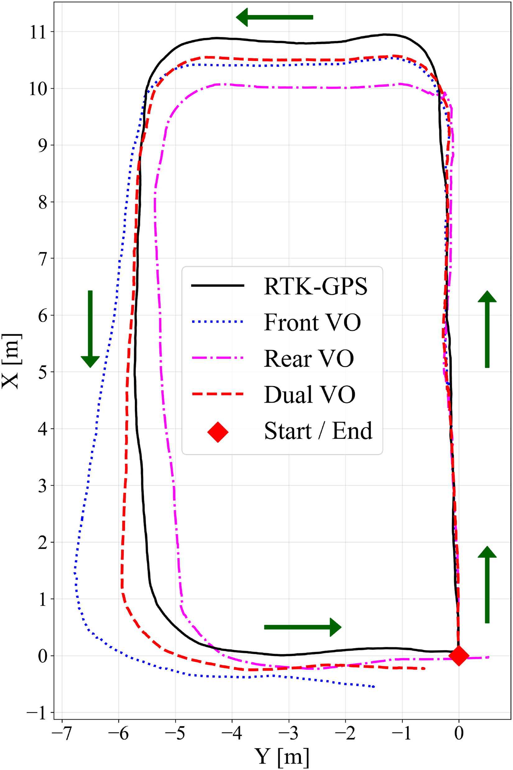
Trajectory comparison of front VO, rear VO, and dual VO with the RTK–GPS ground truth. VO: visual odometry; RTK: real-time kinematic; GPS: global positioning system.
Table 6 summarizes the quantitative performance metrics, including RMSE, mean error, maximum error, and SD. The front and rear VOs yielded RMSE values of
Comparison of trajectory estimation accuracy (reference: RTK–GPS).

RTK: real-time kinematic; GPS: global positioning system; VO: visual odometry; RMSE: root mean square error; Std Dev: standard deviation.
Mapless navigation
To validate the autonomous capabilities of the proposed platform, a mapless navigation experiment was conducted in a previously unknown environment. In this scenario, the robot was tasked with navigating toward a predefined goal coordinates without reliance on pre-built occupancy grids or external localization infrastructure. Consequently, the system depended exclusively on its onboard perception modules and local motion-planning algorithms to detect obstacles in real time and generate collision-free paths.
As depicted in Figure 11, the testing environment featured a constrained spatial layout. Obstacle area
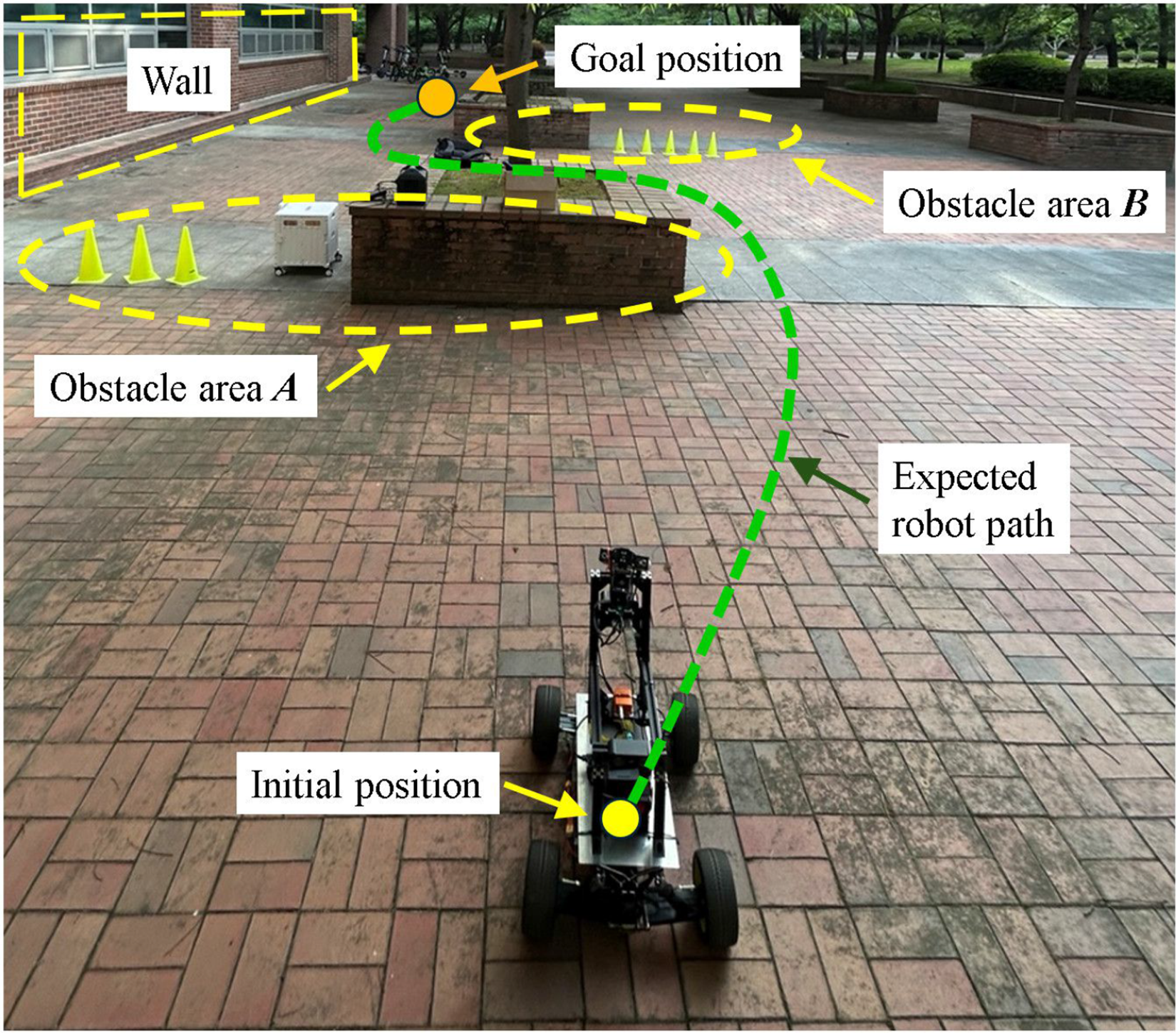
Experimental environment for mapless navigation.
The navigation framework was implemented using the ROS 2 Nav2 stack. Specifically, the A
Figure 12 illustrates the experimental outcome, displaying the global and local costmaps alongside the robot’s executed trajectory. The inflated obstacles in the global costmap correspond to areas
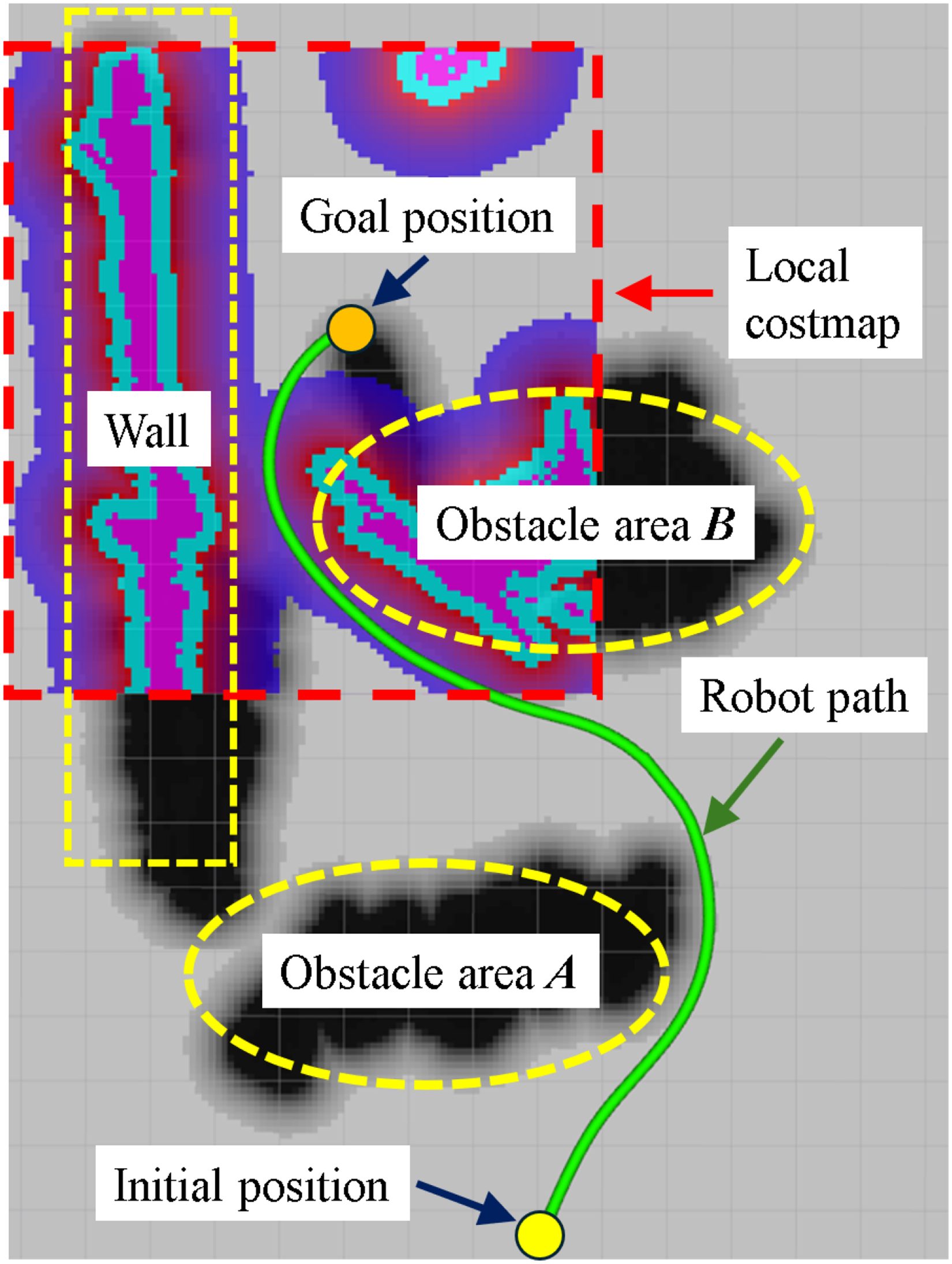
Experimental result of mapless navigation: Global/local costmaps and the executed trajectory.
The results confirm that the robot successfully avoided all obstacles and reached the target location smoothly. Despite the restricted maneuvering space, the integrated system demonstrated robust performance, effectively combining real-time terrain perception, costmap inflation, and adaptive Ackermann control. This experiment validates the platform’s utility for real-world service applications—such as patrol, inspection, and delivery—in environments where prior map data is unavailable or unreliable.
SLAM-based 3D map generation
To assess the platform’s capacity for dense environmental reconstruction, a 3D SLAM experiment was conducted in an outdoor setting characterized by various static structures, as depicted in Figure 13. The mapping framework was implemented using real-time appearance-based mapping (RTAB-Map), a graph-based RGB-D SLAM algorithm fully integrated with the ROS 2 ecosystem. 31
Experimental environment for 3D SLAM and map generation. 3D: three-dimensional; SLAM: simultaneous localization and mapping.
In this configuration, the front-facing stereo camera served as the primary sensor, providing synchronized RGB images and aligned depth maps. RTAB-Map processed this incoming RGB-D stream to internally compute VO and extract features for loop closure detection. This demonstrates the platform’s capability to support standalone SLAM packages without reliance on external state estimation modules. The resulting constraints were added to a pose graph, which was continuously optimized online to maintain global map consistency and correct for accumulated drift.
During the experiment, the robot was tele-operated via a Zigbee-based remote controller to traverse the environment along a predetermined path similar to the trajectory shown in Figure 12. As the robot moved, RTAB-Map incrementally reconstructed a dense 3D map of the surroundings in real time. By operating in RGB-D mode, the system directly utilized the high-fidelity depth data generated by the stereo camera, ensuring accurate spatial representation without the computational overhead of redundant disparity calculations.
Figure 14 presents the resulting 3D point cloud map. The reconstruction captures the geometric structure of the environment with high fidelity, clearly distinguishing vertical walls, obstacles, and free space. This outcome demonstrates the system’s capability to perform real-time 3D SLAM and construct globally consistent maps in previously unknown environments.
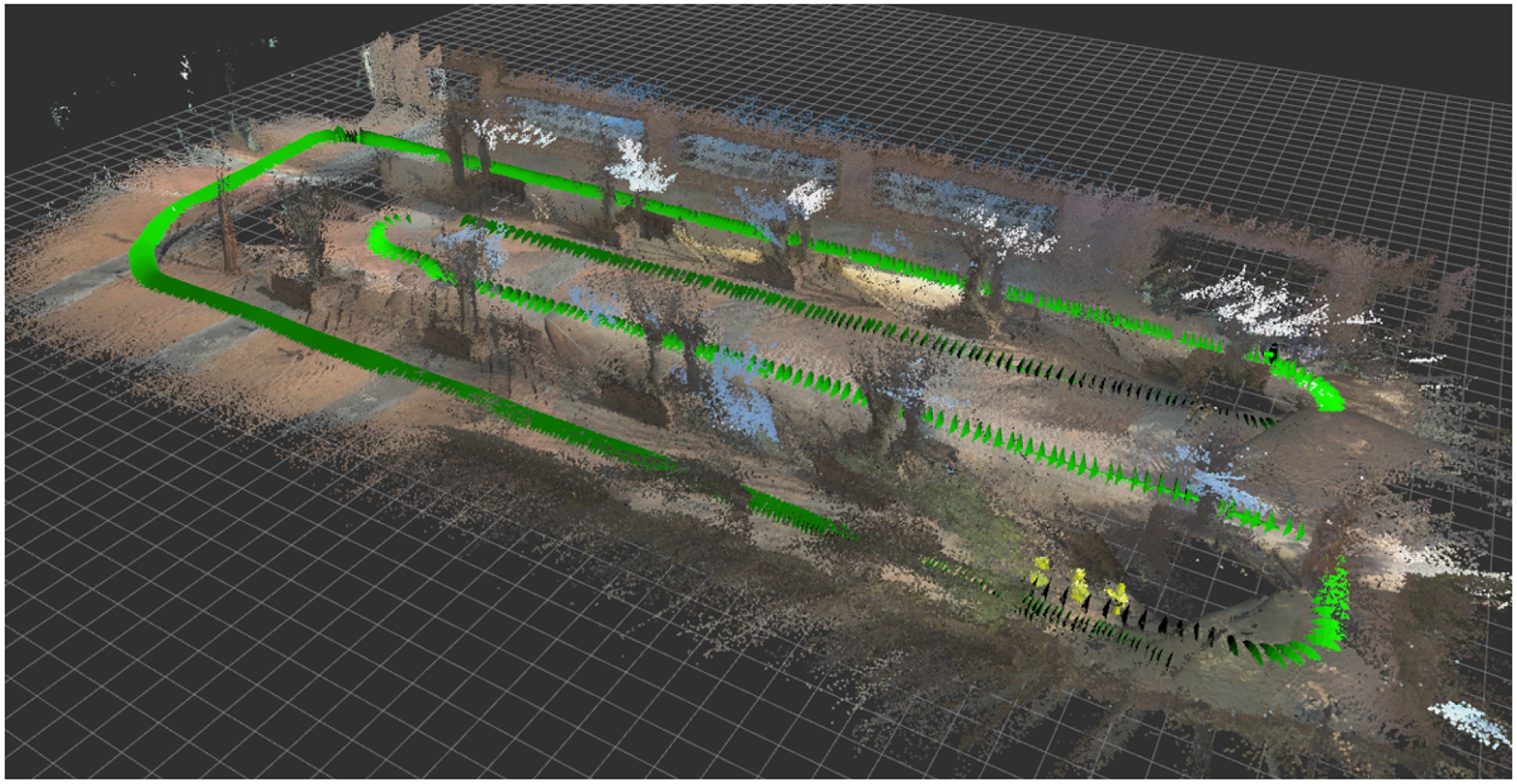
Experimental result of 3D SLAM: The reconstructed point cloud map. 3D: three-dimensional; SLAM: simultaneous localization and mapping.
The successful execution of this experiment validates that the developed platform is well-suited for tasks requiring comprehensive 3D environmental understanding, such as autonomous inspection, exploration in complex outdoor environments, and digital-twin generation for infrastructure modeling. Furthermore, the results underscore the platform’s ability to seamlessly integrate and operate multiple computationally intensive perception modules within a unified ROS 2 framework. The demonstrated 3D mapping capability thus highlights the system’s value not only as a reliable service robot but also as a flexible testbed for developing and evaluating diverse SLAM and perception algorithms.
Conclusion
This paper presented the design, implementation, and experimental validation of a compact Ackermann-steered mobile robot platform equipped with a dual VO system and active perception capabilities. Built upon the ROS 2 framework, the proposed system ensures modularity and extensibility, allowing researchers to seamlessly integrate and benchmark various algorithms for perception, localization, and navigation.
Experimental evaluations in outdoor environments demonstrated the platform’s robustness and quantitative performance. Velocity tracking tests confirmed stable motion control with an RMSE remaining below
Future work will aim to enhance the platform’s autonomy in highly dynamic and crowded environments. Specifically, we plan to leverage the integrated pan-tilt RGB-D perception system to implement active visual tracking algorithms for HRI and surveillance tasks. Additionally, to mitigate the mechanical resonance observed at specific velocities, we intend to adopt model-based control strategies, such as MPC, and reinforce the mechanical damping of the sensor mounts to ensure superior stability.
Footnotes
Funding
The authors disclosed receipt of the following financial support for the research, authorship, and/or publication of this article: This work was supported by the National Research Foundation of Korea (NRF) grant funded by Korean Government through MSIT under Grant No. RS-2024-00337584.
Declaration of conflicting interests
The authors declared no potential conflicts of interest with respect to the research, authorship, and/or publication of this article.
Data availability statement
Data sharing not applicable to this article as no datasets were generated or analyzed during the current study.