
Abstract
This article studies the problem of painting an obstacle free rectangular region by a swarm of mobile robots. Initially the robots are deployed randomly within the target area subject to the condition that the distribution is d*-dense, where
Introduction
The concept of swarm mainly emphasizes on the collective, cooperative and coordinated behaviour of a group of insects for performing a particular task. This concept of swarm is blended with the concepts of distributed algorithm to generate several applications for multi-robot coordination where the members of the swarm are identical. Together with the development of these physical robots, the research interests have been shifted towards the development of suitable algorithms that are capable of handling the coordination among multiple robots to perform large tasks. Among various applications of swarm of robots, research interest is gearing up in the field of area coverage. A swarm of mobile robots will achieve complete coverage of an area if and only if every location of the area is reached or scanned by at least one robot in the swarm. One of the applications of multi-robot area coverage is searching and rescuing of victims 1 in various hazardous or hostile environments. Moreover, the concept of area coverage may also be used in various applications 2 such as car body painting, area painting, lawn mowing and milling, sweeping, terrain exploration and mapping. Since covering an area is same as painting an area, from now onwards painting and covering are used interchangeably throughout this article.
This article addressed the problem of coverage or painting of a known obstacle-free rectangular area by robots with limited visibility range. Previous research works on multi-robot area coverage 3,4 –7 consider that the robots are having unlimited visibility, where each robot in the swarm can see the entire space. However, the visibility range of a robot depends on the power of the sensor or camera attached to it. To reduce the cost of mass production of robots in a swarm, the robots are intentionally made very simple with limited capacity. In this scenario, a robot having unlimited visibility is quite unnatural. In this article, we assume the robots to have limited visibility, so that they can view up to a fixed distance.
We have assumed that a swarm of N robots are deployed randomly inside the rectangular area, and each robot is having a visibility capacity up to a fixed distance d. However, it is assumed that the initial distribution is d*-dense, where
The proposed algorithm is based on CORDA 8 model or wait–observe–compute–move model. CORDA is a theoretical model. It is a step towards real-life movements. In this model, a robot’s action (throughout the algorithm) can be viewed (and hence programmed) as a sequence of computational cycles when each cycle consists of four phases, namely wait (optional), observe, compute and move. Whatever a robot observes in observe phase is used to compute the next destination in compute phase and finally moves to the computed destination in move phase. These phases are non-overlapping, and each of these phases are carried out sequentially by each robot. It can be pointed out here that a robot observes its surroundings according to its local system. These features make the robots easier to program and thus make the solution cheaper. In most of the previous works found in the literature (except one), regarding coverage problem, CORDA model has not been considered. In those algorithms a robot can carry out all types of actions, such as viewing their surroundings, computing, moving, and communicating with teammates, all at a time, that is, simultaneously over a continuous period of time. These are features of a more powerful robot. Interestingly, in the domain of other problems than coverage, such as gathering and partitioning, 2,9 researchers consider only CORDA model because of its simplicity. The only work on coverage problem using CORDA reported in the literature are based on unlimited visibility. In the proposed algorithm, the robots are assumed to follow full-compass model in which they agree on the direction and orientation of their local axes. They are also assumed to be asynchronous.
Most of the previous works 4 –7,10 –12 in this area have considered the presence of obstacles within the area and as a result, the existing algorithms involve large amount of complex calculations for a relatively weak model. However, covering an area without obstacle using the same complex calculations takes unnecessary extra time and make the solution more complicated. The robots used in these algorithms are not simpler as they need a large amount of memory with great computational ability. Moreover, active communication among the robots and prior information of the environment are also necessary in some of the existing solutions.
Getting a solution to the coverage problem becomes challenging when robots are assumed to be very simple with respect to computation and communication power, availability of memory and so on. The algorithm that we are going to propose here shows that the solution of the coverage problem can be achieved using a more realistic and relatively stronger model with simpler robots. In the proposed algorithm, the robots are neither controlled by any central authority nor any external body. The robots are assumed to be oblivious or memoryless in a restricted manner as they need to retain only a very small amount of information. The memory requirement is comparatively low. In addition to that, our aim is to design a solution, with these robots, which minimizes the cost as much as possible. Thus, an efficient solution would restrict redundant work done by the robots. By this, we mean that in an ideal situation any portion of the area should not be covered by more than one robot. Under the circumstances, direct communication among the robots seems to be absolutely necessary. When the robots work in a team, communication among the team members is also required. Most of the algorithms present in the literature assume that robots can communicate among themselves while covering the region. In the proposed solution, instead of direct communication, only a passive communication among the robots is assumed which further makes the solution less costly and simpler compared to the existing ones. By passive communication we mean the mode of communication is only through observing others without any kind of message passing or so. However, it is not expected that two robots observe their surroundings simultaneously at the same time. In the proposed solution, repeated coverage is avoided, though the robots perform their task independently without having any active communication with other robots.
Second section discusses the related research works. Third section includes the problem definition, models and assumptions in detail. Fourth section has two subsections. The first one discusses the painting algorithm and in the second subsection, the correctness of the algorithm is established. In the fifth section, the completion time of phase I is calculated. The simulation of the proposed algorithm is discussed in sixth section, and we conclude the article in the seventh section.
Related work
Various research works that dealt with multi-robot coverage problems have been reported. In the existing works, the problem definition varies in a way that the area to be covered may or may not contain obstacles. Moreover, the robots may have different capabilities with respect to visibility range, limited or unlimited. With all these variations, the main approaches that are followed in the existing algorithms are classified into two categories, team-based approach 5,6 and individual approach. 3,4,7 In the team-based approach, multiple robots move and perform their task in a team. Depending on different situations, a team can be subdivided into two teams and then after achieving their targets, the teams unite again and proceed further as a single team. Individual approaches are based on the concept of virtually dividing the whole area into a number of disjoint cells, and each robot is assigned the job of covering at least one such cell. In this approach, the robots usually work independently from each other.
The algorithms proposed in previous works 4 –7 consider the presence of obstacles in the area and the robots with unlimited visibility. Kong et al. 4 used a distributed approach to solve the problem. They followed the ‘boustrophedon cellular decomposition approach’ to divide the whole region into some cells. Full-compass and asynchronous models are assumed. Moreover, the robots need to maintain and share among themselves the adjacency graphs that are generated by each of them separately, to represent covered and uncovered cells. This results in a requirement of a large amount of memory and computational power of the robots. Latimer et al. 5 provided a fully synchronous team-based solution. They assumed full-compass model. The robots within a team always maintain communication, coordination and synchronization with each other which make the solution expensive and unrealistic. Moreover, the algorithm may result in repeated coverage. Rekletis et al. designed a team-based solution 6 and a distributed solution. 7 In the study by Rekletis et al., 6 the models used are full-compass and fully synchronous. There are two types of robots in a team: explorers, to explore the cell boundaries, and coverers, to cover the cell explored by the explorers. Throughout the algorithm, the explorers need to communicate among themselves which once again increase the overhead. Moreover, coverers may result repeated coverage by covering the area which is already covered by the explorers. On the other hand, in the study by Rekletis et al., 7 the model assumed is also full-compass but asynchronous. The algorithm uses the concept of building Reeb graphs by each robot and then sharing and updating of the same among themselves. This makes the algorithm complex. In addition to that, another limitation of the algorithm is its assumption of a special type of initial distribution of the robots, where robots are deployed in regular interval along the lower boundary of the region.
Very less works have been reported for the coverage problem with limited visibility and obstacle-free area. Although an algorithm that is meant for areas with obstacles is also applicable in an obstacle-free case, however, complex solution for a simpler problem makes the solution unnecessarily complicated. Das et al. 3 presented a completely distributed simple algorithm to paint/cover a region without obstacle by following the basic CORDA model. They have considered, rather a stronger model, direction-only and asynchronous, for the solution. There is only passive communication among the robots in which the robots do not exchange information among themselves. The robots take the decisions regarding any type of movement based on the location of other neighbouring robots. The algorithm is able to successfully cover the whole region without repeated coverage and collision among the robots. Considering the presence of obstacles, Fazli et al. 10,11 proposed an offline coverage algorithm where the robots were initially aware of the entire environment including static obstacles. The authors here assumed that the robots are of limited visibility capability. However, the assumption of known environment dilutes most of the challenges faced in case of limited visibilities. Moreover, this algorithm demands the presence of a significant amount of memory in each of the robots. The robots here cannot be oblivious. Jiao et al. 12 proposed a decomposition algorithm for boundary coverage problem in case of a single robot as well as multiple robots. These algorithms assume the existence of polygonal obstacles. The robots are assumed to have unlimited visibility. However, their line of sight might be obstructed by the presence of obstacles.
The proposed algorithm shows that the coverage problem can be solved in a more realistic manner. In the proposed work, although the robots know the dimension of the region, they are completely unaware of the environment beyond its visibility range. If a robot does not see any of the boundaries, it is even completely unaware of its position within the area. Moreover, there is only passive communication among the robots. The robots are completely autonomous, and they are able to work independently from each other. As the communication and computational overheads are less, simple robots are used in place of complex robots. With respect to the existing algorithms, the proposed one is based on comparatively stronger model as it is designed by following the standard CORDA model, asynchronous and full-compass model. Most of the previous works have not considered the standard CORDA model 8 for designing the algorithms. The algorithm is also capable enough to accommodate the robots with different speeds, caused due to non-plane surfaces. The algorithm takes finite amount of time to solve the problem without any collision and repeated coverage.
Problem definition, assumptions and models
Our problem is to paint an obstacle-free rectangular area by a swarm of robots. The area is bounded on all sides. Assuming that no two robots can occupy the same position, the robots are randomly distributed over the region subject to the condition that the distribution is d*-dense. If vertical lines (hypothetical) are drawn through each robot then in d*-dense distribution, the distance between two consecutive vertical lines should be less than or equal to d*. In this article, we assume that
(a) Robots are identical and homogeneous with respect to their computational power. (b) They are autonomous in the sense that there is no central control. All the robots execute the same algorithm independently of the others to achieve the goal in a completely distributed way. (c) Robots have passive communication among themselves. The robots do not exchange any kind of information with others. (d) All robots are allowed to move on a plane. (e) Robots are having limited visibility. Each robot can view only those robots that are located at the most at a fixed distance d from it. So, the area of visibility for each robot can be measured by a circle (known as circle of visibility) with radius d (known as visibility radius). (f) Full-compass: Each robot has its own local coordinate system in which they are placed at the origin. The robots agree on directions and orientations of their local axes. (g) The robots are assumed to follow CORDA model. A computational cycle is defined to be a sequence of observe, compute and move steps. Each of the robots executes same instructions in all the computational cycles. Once a robot completes one computational cycle, it starts executing the next one. This process is repeated until the whole job is completed. The actions taken by a robot in compute and move steps, entirely depend on the observe step. In some situations, an observation might lead a robot not to change its position in move step. In such cases, the robot seems to be idle, though it is actually executing all the three steps. The duration of a computational cycle is the total time taken by the robot to execute observe, compute and move steps in one cycle. In each move step, a robot moves at the most
Coverage algorithm
The first part describes the proposed algorithm. The correctness of the algorithm is proved in the second part.
Description of the algorithm
The basic idea of the algorithm is to divide the whole region into a number of disjoint parallel vertical strips. Each robot will be assigned one strip for painting. The robots have limited view of their neighbours. Based on the gathered information in the observe step, a robot calculates its own strip boundaries. The robots retain the information regarding strip boundaries using some variables that are updated during the execution of the algorithm. Let us first discuss some terminologies that will be used later. (a) Nearest right neighbour (nrn)/nearest left neighbour (nln): For a robot R, the nearest right (left) neighbour is the robot R′ such that (i) R′ is on the right (left) of R, (ii)
In the first phase of the algorithm, a robot calculates the boundaries of the strip which is to be painted by itself and in the second phase, the robot actually paints the strip. From the position where the robots are deployed initially, each of the robots moves in the upward direction (according to their own local coordinate system) first until it reaches the upper boundary of the region. It then moves in the vertically downward direction to reach the lower boundary of the region. While traversing this route, the robot finalize its strip boundaries, left, right, bottom and top. After reaching the lower boundary of the strip to be painted (in general, the lower boundary of the region), the robot starts painting from the bottom left-most corner of the strip. It is assumed that movements of the robots are not instantaneous.
A robot finally fixes its right and left boundaries at a distance
Variables to be considered by the robots R together with their descriptions and initial values.

Observe
According to the local co-ordinate system, the robot R first observes the position of the neighbours within its area of visibility. Suppose, the robot R have
Compute


Destination Coordinate

UB: upper bound; LoB: lower bound
Move
In this step, the robot moves to the destination point
Correctness proof
Suppose, R1 and R2 be two robots, moving with velocity v1 and v2, respectively, such that initially
Lemma I
If the robots move with equal speed, during the first phase of the algorithm, a robot observes its nearest left and right neighbours at least once.
Proof
When two consecutive robots, say R1 and R2 (nearest left and right neighbours of each other), move in opposite directions they must pass through the visibility circle of each other. In case, a robot has more than one nearest neighbour (left or right) on the same vertical line, at least one of them would pass through the visibility circle of the robot. We consider the following two cases separately.
Case (I): When R1 and R2 are moving in the same direction (say upward direction).
In this case, since they are moving with the same velocity, the vertical distance between them remain same as long as they move in the same direction. Hence, initially if they are not visible to each other, as long as they move in the same direction, they do not become visible to each other.
Case (II): When R1 and R2 are moving in the opposite direction.
Figure 1(a) describes this situation when R1 and R2 are moving in the opposite direction. When R1 is at A, let R2 be at B. R1 takes the snapshot of its surroundings at A and then at A′. By the time R1 reaches A′, R2 reaches B′ passing through the visibility range of R1. We are to prove that either R1 from A observes R2 at B or R1 from A′ observes R2 at B′.

Illustrations for the proof of lemma I.
Here,
It can be noted here that a parallelogram with two opposite hands (of size
According to our initial assumption the initial distribution of robots is d*-dense. Hence R1 must see R2 either from A or from A′. Now, if R2 halts at B and B′ for taking snapshot, the same argument holds for R2 also. Otherwise, if at B, R2 is in motion, then it must halt somewhere in between B and B′ from where it observes R1 on
Lemma II
If it is given that the ratio between the velocities of two robots can be at the most r, a robot observes its nearest left and right neighbours at least once if the initial distribution is D*-dense, where,
Proof
Herein, we consider the two cases separately when two consecutive robots move in the same direction or opposite.
Case (I): Let us first consider the case when two consecutive (horizontally) robots R1 and R2, which are the nearest left and right neighbours to each other, are moving in the opposite direction along the vertical line passing through their initial position and they pass through each other’s visibility range. Let us assume that R2 is moving faster than R1.
Let A and A′ denote the positions of the robot R1 in two successive computational cycles from where R1 takes the snapshot of the surroundings in the observe step as shown in Figure 2. Let R2 be at the horizontal distance

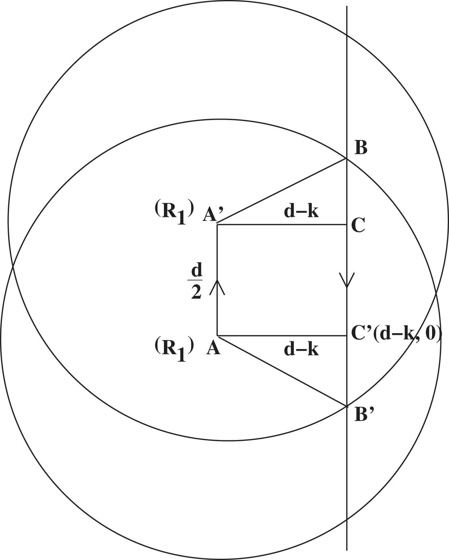
Illustrations for the proof of case I of lemma II.
It is required to be pointed out here that when we consider
From lemma I and our initial assumption, k cannot be less than
From equation (1), we can say that the upper bound of
Suppose, it is given that
Case (II): When R1 and R2 are moving in the same direction.
A situation may arise, when two robots R1 and R2 never move in the same direction. In particular, say R1 is initially on the top boundary, R2 is on the lower boundary of the region and they move with equal speed. Thus, they never move in the same direction provided there are no other robots on their vertical lines. Hence, case II should not be considered in drawing any conclusion.
Hence, on the basis of case I, we can conclude that when it is given that the ratio between the velocities of two robots can be at the most r, the proposed algorithm is valid for D*-dense initial distribution, where
Corollary
Since D* is real and greater than 0, r cannot be more than 3 in any case. Thus,
Now, in case more than one robots are on the same vertical line initially, these robots need to compute the upper and/or lower boundaries of their strips without any conflict.
Lemma III
After viewing a robot on the same vertical line, to make a total agreement with it regarding the common boundary between them, a robot have to wait a maximum of
Proof
We assume that two robots R1 and R2 are deployed on the same vertical line and let v1 and v2 be the velocities of R1 and R2, respectively. They may or may not view each other initially. Suppose R1 finds R2 on the same vertical line during the vertical movement in phase I. To come to a total agreement with R2, regarding the common boundary, R1 has to ensure that R2 observes R1 in its current position. Thus, in the absence of direct communication, the only option for R1 is to wait at that position for some time to make itself visible to R2. The same reason holds for R2 also. Thus, if a robot finds another robot on the same vertical line, it does not change its position for few computational cycles. R1 waits at the same position until it observes R2 at the same position for two consecutive observe phases to understand that robot R2 is not changing its position. Moreover, it has to wait there for some more time to give R2 an opportunity that R2 also observes R1 in the same position for two consecutive observe phases. When the robots do not move, the time gap between its two consecutive observe steps is T0.
Figure 3 shows the timelines of two robots R1 and R2, which are initially deployed on the same vertical line. Suppose R1 first observes R2 on the same vertical line at the time instance A. At time A, the distance between R1 and R2 is less than d. However, if R2 is not in its observe step, R2 does not see R1 at time A. In the worst case, after
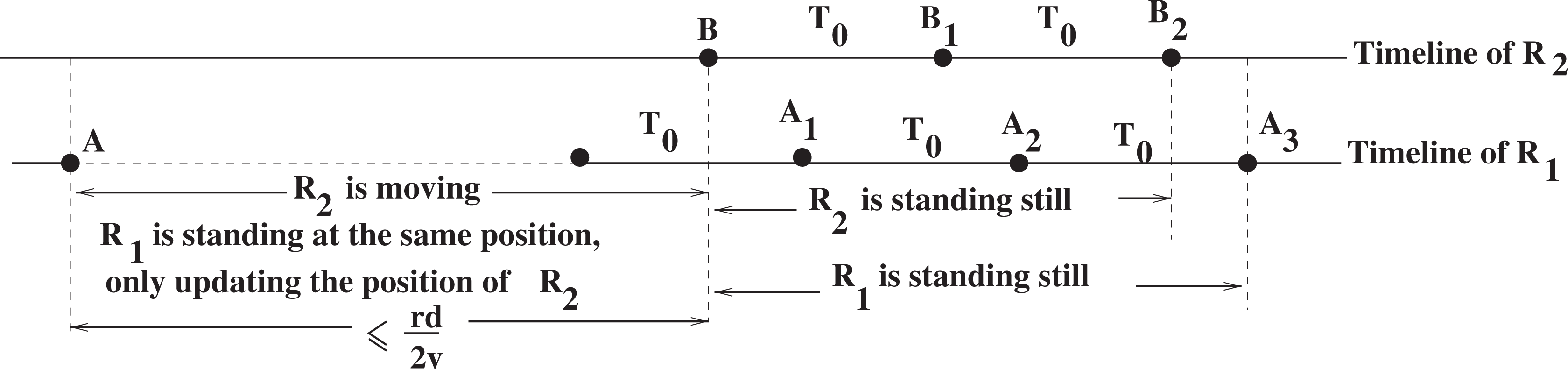
Timelines for R1 and R2. Black dots on the timelines indicate the instances of when R1 and R2 are passing through observe state.
During the time between A and B, R1 observes R2 on the same vertical line if their distance is less than d. During that period, R1 updates the position of R2 staying in the same position. If R2 goes beyond the distance d, R1 goes back to its normal action resuming vertical movement. □
Lemma IV
For successfully identifying the proper right and left boundary of the strip to be painted, a robot must wait Tw amount of time on the lower boundary of its strip before starting phase II, where
Proof
By lemmas I and II, we can say that if two neighbouring robots (their hdist is less than D*) traverse the whole path from their initial positions to the upper boundary of the region and then to the lower boundary, then during their journey they must recognize each other provided they do not move more than r times faster than each other. However, if the robots are initially deployed in such a way that more than one robot fall on the same vertical line, then they do not need to traverse the whole path.
One such situation is described in Figure 4, where robots R1 and R2 are on the same vertical line initially and R3 is the nearest right neighbour (nrn) of them. According to our algorithm, in this case, R2 observes R1 on the same vertical line, it fixes the upper boundary and then start moving in the downward direction to reach lower boundary to start painting. Similarly R1 also fixes its lower boundary following the same rule and then start moving towards upper boundary of the region. Thus, R1 and R2 do not traverse the whole path from their initial positions to upper boundary and then to the lower boundary of the region. The question may arise here that: Do they

Illustrations for the proof of lemma IV.
For calculating the waiting time, let us consider Figure 4. Let us assume that R2 is initially at a height h from the lower boundary of the region. As we have assumed that initially R1 is visible to R2, R2 fixes its upper boundary in the very beginning and in phase I R2 needs to move only in the downward direction to get ready for painting. However, if we assume that R3 is not visible to R2 initially, then R2 cannot start painting until it observes R3, that is, until R3 reaches the lower boundary.
Initially R3 is at least at a distance of
However, minimum value of v3 as expected by R2 is
The expression for Tw shows that for a faster robot, waiting time is less compared to a slower one. However, it can be noted that the upper bound derived here is quite a loose upper bound. Depending on all possible variations in initial distribution and speed, the worst case is considered. For example, for the robots that are placed on the same vertical line, to fix the upper and lower boundaries (at least one) they require at the most six extra computational cycles. However, in that case they do not need to traverse the whole of 2L distance. □
Theorem I
The whole region is painted by the robots without any overlapping, and the process is completed within a finite amount of time.
Proof
In the initial distribution, a robot may not observe its nearest neighbours. In those cases, robots determine its strip boundaries on the basis of the positions of its visible nearest neighbours. Thus, the initial formation may result in overlapping strips. During the movement of a robot in phase I, first towards upper boundary and then towards lower boundary, robots, being able to observe the position of their nearest neighbours at least once (by lemmas I, II and IV), can uniquely and unanimously determine the strip boundaries (left and right). Lemma III shows that the upper and lower boundaries are also computed without any conflict. Hence, the strips defined by the robots are non-overlapping. Moreover, as we have assumed that the boundaries of the region are visible to at least one robot initially, all the strips defined by the robots cover the whole region.
That is, the set of all strips determined by the robots defines a partition over the whole region. Thus, the whole region is painted by the robots without any repeated painting, provided the initial distribution of robots over the given region is d*-dense, where
Theorem II
The movement of the robots are collision free.
Proof
In phase I of the algorithm, each robot moves only in the vertical direction (first upward and then downward) along the line passing through their initial position. Since no two robots can occupy the same position, their lines of movement are distinct, except for those robots whose initial positions are on the same vertical line. If two or more robots are located on the same vertical line, they are always able to view the robot(s) just above and/or below it, once they fall in the visibility range of each other (by lemma III). It can be pointed out here that in each computational cycle, they can see up to a distance d but moves through a distance at the most
Time calculation
Let us once again ‘mention’ the parameters that would influence the total time taken by a robot for completion of phase I: (i) L: vertical length of the rectangular area, (ii) d: visibility radius, T0: maximum time taken by a robot to execute observe and compute steps and (iv) v: velocity of the robot.
Now, as discussed in lemma IV, if all the robots start their computation at the same time, then the maximum time required to reach the lower boundary is

where v is the velocity of the robot, r is a given upper bound on the ratios of the velocities of any two robots;
Thus, the total time of completion depends on the computational capacity (affecting T0), hardware (affecting v) and accessories (can influence d) used by the robots. An e-puck robot, that is used for educational purposes, uses Microchip dsPIC microcontroller with 8 kb RAM and 144 kb flash memory, two miniature stepper motors having speed of 1000 steps/s (controls the robot wheels), proximity sensors with 10–100 Hz capacity (measures the distance of an obstacle from the robot), a colour CMOS camera with resolution 640 × 480 colour pixels, and so on. 13 However, a Koala 2.5, a mid-sized robot designed for real-world applications, uses Dual Core Intel Atom N2800, 1.86 GHz with hyper threading, 4 GB RAM, 40 GB SSD, 2 DC brushed motors with incremental encoders with speed 0.6 m/s (max) and 0.011 m/s (min), 9× ultrasonic sensors that measures distance to the object (range 25–250 cm). 14
Simulation and experimental results
With the help of Player [version 3.2.2]/Stage [version 3.0.2] multi-robot simulation software, the first phase of the proposed algorithm has been simulated to show that the strips are computed correctly within a finite amount of time. It is quite obvious that if a robot can successfully complete phase I within the finite amount of time it would definitely be able to paint the assigned strip within finite time. However, painting procedure and required time of phase II depends on the accessories used by the robots to paint the area which depends on actual implementation. Moreover, the simulation shows that their movements are collision-free.
Simulation environment
For simulation the Player/Stage multi-robot simulation software is used, which is configured on Ubuntu 10.04 (Lucid Lynx) platform. Intel Core2Duo Processor with 3.00 GHz speed and 2.00 GB RAM provided as a hardware support to the Player (version 3.2.2) and Stage (version 3.0.2) software. Several robots are randomly positioned within an obstacle-free rectangular region with fixed boundaries and known dimensions.
The simulation uses 15 green coloured robots with
The local coordinate systems of each robots have identical direction and orientation as the global system and thus full-compass. The robots have equal speed since Player/Stage supports neither unequal speed for the robots nor asynchronicity among them. Thus, in effect, the algorithm has been simulated for a synchronous system. In the changed scenario, the time calculated in ‘Time calculation’ section is no more a good upper bound. A tighter bound can be calculated in a straight forward way as
Results
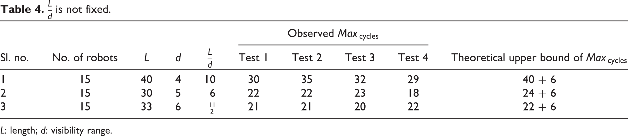
We have represented the results according to two different categories of the parameters involved in the simulation. In the first category, in Table 3, simulation results are shown by varying the values of L and d, keeping the ratio

L: length; d: visibility range.
L: length; d: visibility range.
Initial distribution of the robots corresponding to the second row of Table 4 with L = 30, d = 5.

L: length; d: visibility range.
In each of the cases, we compared the observed value of
Conclusion
This article presents an algorithm to paint a known rectangular region by a swarm of identical, simple, autonomous robots with limited visibility. The robots do not have any type of information exchange among themselves. The only information a robot gets about its visible neighbours is their positions as observed in definite time interval. The solution of the algorithm is designed for asynchronous robots following the basic CORDA model. The robots have full-compass local coordinate system. The algorithm guarantees complete coverage of the given region within a finite amount of time without any repetition. The proposed algorithm is valid only for a D*-dense initial distribution, where
Footnotes
Authors’ note
This article is a revised and expanded version of the paper entitled ‘Painting an Area by Swarm of Mobile Robots with Limited Visibility’, 15 presented at 6th International Conference on Information Processing at Bangalore, Karnataka, India during 10–12 August 2012.
Acknowledgements
The authors are grateful to the anonymous reviewers whose concern and suggestions help in improving the presentation and correctness of the article.
Declaration of conflicting interests
The author(s) declared no potential conflicts of interest with respect to the research, authorship, and/or publication of this article.
Funding
The author(s) received no financial support for the research, authorship, and/or publication of this article.