
Abstract
This work is motivated by the possibility that hemiplegic patients might achieve complete functional recovery of lower limb joints, muscles, and nerves by stretching and bending the lower limbs using rehabilitation training. A model of a rigid–flexible coupled lower limb rehabilitation robot is established and mechanically analyzed to satisfy both the control of various movement loci with flexion and extension and the requirements of rehabilitation training. According to the Denavit–Hartenberg method and the influence coefficient method, a kinematic model is established. Moreover, a static equilibrium equation is presented, and two motion planning methods for rigid branched chain movement are put forward. Fluctuation parameters are proposed to estimate the tension of every wire. A planning strategy of different rigid branched chains is analyzed during mechanical simulation using MATLAB [version 2013a]/SimMechanics along a specific trajectory. The law of wires and rigid branched chains is achieved. The wires’ working performance of a parallel robot can be improved by introducing a rigid branched chain. During the dynamic simulation of the mechanism, other wires’ tension changes are analyzed by setting the wire’s tension (100 N) of a coupled branched chain. The wire’s tension performance in the system is evaluated by its fluctuation performance. Finally, it is validated that the strategy of angle bisection is the best. The results prove that the rigid–flexible parallel rehabilitation robot can realize gait rehabilitation training of lower limbs, which leads to the servo control research of this robot.
Introduction
Rehabilitation training is the major method of treatment and exercise for physical rehabilitation. Rehabilitation training can realize the periodic movement of a trainee’s limbs with the help of a robot. To date, theory and practice have verified that sportive rehabilitation planning can protect limbs from muscular atrophy from disuse and ankyloses and promote nerve conduction and blood circulation, finally regaining limb motion ability. In lower limb rehabilitation training, robots often use rigid bodies as their mechanisms. A robot has been developed by Free University, Germany. 1,2 A double crank-rocker mechanism is adopted in its gait mechanism, but it has only one degree of freedom (DOF) with a single function and thus cannot realize complex movement. Moreover, the LOPES (LOwer-extremity Powered ExoSkeleton) gait rehabilitation robot has been developed by Veneman; this robot adopts an exoskeleton structure and comes in two models: active and passive. This equipment could accomplish specified gait training by the leg electromyography measurement results. 3 A 2-DOF lower limb rehabilitation robot has been developed at the University of California, United States. It is able to control the end point between the robot and the patient through a V-shaped mechanism, and it features reversibility. 4,5 Moreover, at the Federal Institute of Technology in Zurich, Switzerland, a new type of rehabilitation robot, Lokomat, has been developed. It could realize a patient’s gait movement via a wearable device with 4 DOF. 6,7 In China, research in this area has also made progress. Harbin Engineering University has developed a robot with a parallel mechanism to control a footboard to realize stride, which could meet the need of lower limbs having different motion trajectories, but it is too large. 8 In addition, a lower limb exoskeleton apparatus has been developed by Shanghai University, Zhejiang University and other institutions. 9,10 Rotary motion could be realized by the linear driving of an electric cylinder, and the movement of lower limb joints can also be realized. Wire-driven parallel mechanisms have the advantages of fast velocity, small inertia, good flexibility, and a simple structure. 11,12 Colombo et al. have controlled trunk movement using wire traction in Germany and have thus realized in accordance with gait motion control. 13 A horizontal lower limb rehabilitation robot has been designed via a wire-driven parallel mechanism by Keiko Homma in Japan. 14 Arm exoskeleton (CAREX-7) and a controller for dexterous motion training or assistance are designed by Sunil K Agrawal and his team at Columbia University. The CAREX-7 includes an additional wrist module compared with CAREX, and eight wires are routed through the exoskeleton cuffs to drive the whole-arm motion. Based on the “assist-as-needed” paradigm, a novel wrench-field controller was designed to regulate a needed wrench (force and torque) on the hand for assisting its dexterous manipulation. 15,16 In particular, it emphasized the security of the wire-driven apparatus and was the subject of experimental research aiming to vary rehabilitation movement patterns. All of the abovementioned research verifies the feasibility of a wire-driven parallel mechanism in the field of rehabilitation robots. A lower limb rehabilitation robot with a wire-driven exoskeleton has been investigated at Harbin Engineering University. 17 The workspace of the exoskeleton robot using single wire traction was analyzed, and an experiment on gait control was established. Research has shown that the manipulator’s workspace is limited by the position of the wire-driven wheel; in particular, when the manipulator approaches the border of the workspace, control error increases and wire tension quality is weakened. This influences the driving characteristics of the system and the controlling effect of lower limb motion. In view of the multiple motion trajectory and flexibility requirements of a lower limb rehabilitation robot, this article proposes a rigid flexible coupled rehabilitation robot with bending and stretching lower limbs. The motion planning of a rigid branched chain was achieved, and the fluctuation of every wire’s tension was studied through simulation. This validates the mechanism of a rigid–flexible coupled robot in rehabilitation training and provides facilities for a servo control strategy.
Mechanism of rigid and flexible coupled robot
A rigid and flexible coupled robot based on a wire-driven parallel robot can control the winch position of a certain wire branch through a rigid branched chain. In a lower limb rehabilitation robot with flexion and extension, a completely restrained position mechanism is formed by three wires pulling one towing point, which is linked to the trainee’s lower leg. In addition, a rigid branched chain has a parallel connection with one of the wire branched loops shown in Figure 1. Wire traction not only overcomes the difficulty in distribution but also minimizes the inertia and improves the dynamic control performance of the system. Further, the force limitation of the trainee’s initiative can be reduced by a flexible wire under force closed-loop control. This control method can improve the security of the system.

(a) Model of rigid–flexible rehabilitation robot for bending and stretching lower limbs. (b) Prototype of rigid–flexible rehabilitation robot for bending and stretching lower limbs.
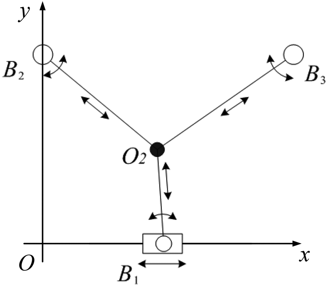
The robot model is shown in Figure 2. Oxy is taken as the fixed coordinates of the system, O2 is the wire-towing point, and
Rigid–flexible rehabilitation robot for bending and stretching lower limbs.
Kinematic analysis
Figure 3 displays the simplified model of the flexion and extension of the trainee’s lower limbs. The fixed coordinate system is

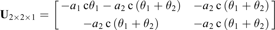
where s = sin and c = cos.

Simplified model of trainee’s flexion and extension of lower limbs.
The length of the wire can be determined by

Substituting equation (1) into equation (2), the inverse relationship of the wire’s position can be deduced. Wire length l1 is also affected by the rigid branch due to the position of pulley B1.
Passive issues regarding the robot position can be solved using the “Triangle” method. The lengths of l2 and l3 are given, and the position of towing point O2 can be obtained by

Taking the derivative of equation (1), the velocity relationship between the trainee’s lower leg and thigh is given as

From the derivative of

Substituting equation (4) into equation (5), the inverse relationship of velocity can be written as follows
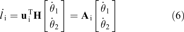
where
From the derivative of equation (4), the acceleration relationship between the lower leg and the thigh could be written as

where

Taking the derivative of

Substituting equation (7) into equation (8), the inverse relationship of acceleration can be written as follows
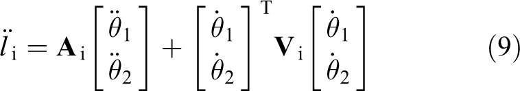
where
Here, the kinematics model of the robot has been completed. Because of its position, the velocity and acceleration of the joint are obtained through equations (1), (2), (6), and (9), and we can know the length, velocity, and acceleration of every wire. All of these together lay a foundation for the dynamic analysis and servo control of the robot.
Motion planning
which is simplified as follows

where
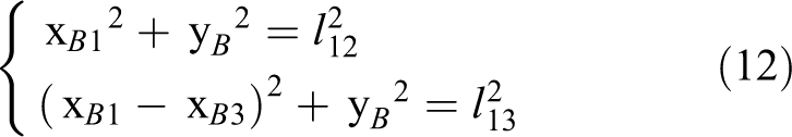
In the first method, the lengths l2 and l3 of wires 2 and 3, respectively, may be achieved when the desired motion position of the towing point is known. l12 is the distance between points B 1 and B 2, l13 is the distance between points B 1 and B 3. Based on the geometrical relationship, the equation can be written as
According to the law of cosines, this is given by

Through (2), (12), and (13), it can be deduced as

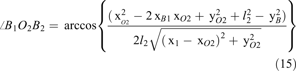
Finally, the equation of the angle can be written as
In the second strategy, the position of xB1 is known,
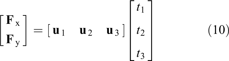
This is a redundant driving system, and the wire tension is nonunique in the entirely restrained wire-driven parallel robot. Suppose that the tension of wire 1 is a constant value during traction; the effect of the motion planning of the rigid branched chain acting on the performance of every wire tension is then analyzed. Meanwhile, the driving characteristics of the robot can be investigated by observing the change laws of the tension of wires 2 and 3. Equation (10) can then be expressed as

where

In order to evaluate the mechanical properties of the system, the fluctuation parameters of the evaluation index are introduced, which measure the fluctuation of the wire traction during the driving process, which can be given by
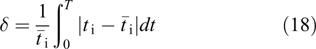
where T is the lower limbs’ training cycle and
The smaller the fluctuation parameter value, the less the energy loss of the wire, the stability of the wire is better, the servo control stability is better, and the safety of the patient is less affected.
Simulated analysis
In Figure 2, the positions of the pulley in the fixed coordinate are

where θ1 and θ2 are in degrees.
Considering the control requirements, the regularity of the wires’ motion is simulated and analyzed. In addition, the relationship of motion between wires and joints is confirmed. By employing the SimMechanics toolbox in MATLAB/Simulink and the rigid–flexible coupled robot mechanism in Figure 2, as shown in Figure 4, the kinematic simulation model of the rigid–flexible lower limb rehabilitation robot mechanism with flexion and extension is established.

The SimMechanics model of the robot with flexion and extension.
The change curves of the length, velocity, and acceleration of wires 2 and 3 under two different planning strategies are displayed in Figure 5.

The (a) length, (b) velocity, and (c) acceleration change curves of wires 2 and 3.
From Figure 5, the ranges of length, velocity, and acceleration are approximately 600 mm, 1250 mm·s−1, and 2650 mm·s−2 for wire 2 and 450 mm, 950 mm·s−1, and 2100 mm·s−2 for wire 3, respectively. The change law of wire 2 is opposite to that of wire 3, and their numerical values in peaks and troughs have a few differences. This reflects the location validity of B2, B3 and shows the rationality of the trainee’s initial state. This further lays a foundation for the mechanism design of the robot and the choice of the driven elements and system calibration in rehabilitation training.
In the process of planning strategies 1 and 2, the position curve of rigid chain motion is shown in Figure 6(a). The curve of positional deviation ΔxB1 is shown in Figure 6(b).

Motion state of rigid chain. (a) Position curve of rigid chain motion during different planning strategies and (b) the curve of positional deviation.
From Figure 6, the ranges of rigid chain movement are 900 mm and 700 mm in planning strategies 1 and 2, respectively. The difference between them is 200 mm. When the traction point is located on the midpoint of the x-axis, that is,
Figure 7 shows the change curves of the length, velocity, and acceleration of wire 1 in planning strategies 1 and 2.

Motion state of wire 1 during different planning strategies. (a) Length changes of wire 1, (b) velocity changes of wire 1, and (c) acceleration changes of wire 1.
From Figure 7, we can observe that the motion laws of wire 1 are basically the same in both planning strategies. The variation ranges of length, velocity, and acceleration of wire 1 are approximately 170 mm, 470 mm·s−1, and 1600 mm·s−2, respectively. This is because the change law of wire 1 is related not only to the motion position of the rigid chain but also to the coordinate yO2 of each point. If yO2 is sufficiently large compared to ΔxB1, the motion law of wire 1 is nearly identical between the planning strategies of the rigid chain, as shown in Figure 7.
The driving characteristics of the wires under the two planning strategies of the rigid chain are analyzed when the output force of the robot is 0. Suppose that the wire driving force is

Tension change curve of wires 2 and 3 in the process of the planning strategy 1.
At present, the fluctuation parameters are written as

(
By applying planning strategy 2, the change laws of t2 and t3 of the wire tension are obtained through simulation, as shown in Figure 9.

Wire tension change curves in the process of planning strategy 2. Tension change curve of (a) wire 2 and (b) wire 3.
The fluctuation parameters of wire tension are now
(
By comparing the fluctuation parameters of the two planning strategies, it can be observed that
In output force planning, the force direction should be perpendicular to and behind the crus to improve the force efficiency and reduce the pressure exerted on the knee. The output force changes with the raising and lowering of lower limbs due to gravity and can be set according to specific conditions in the trainee’s muscle strength. Therefore, in Figure 10, we assume that the output force is 40 N and 20 N in the processes of raising and lowering, respectively.

Output force of robot under given trajectory.
Suppose that the wire tension of the coupled branched chain is

Changing tension curves of wires in the first planning strategy. Changing curve of the tension of (a) wire 2 and (b) wire 3.
Wire tension presents a vertical step at the moments of 1 s and 2.5 s. This is caused by changes in output force according to Figure 10. The change in force direction is continuous, so the effect on wire tension is uninterrupted. The force direction can also influence the magnitude of the wire tension, but it would not cause a vertical step. The tension quality depends on the tension value, thus we calculate the fluctuation parameters of the wire tension at 40 N and 20 N.
The fluctuation parameters of wire tension are

(
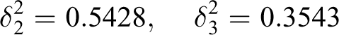
In the second planning strategy, the change laws of wire tensions t2 and t3 could be attained through simulation, as shown in Figure 12.
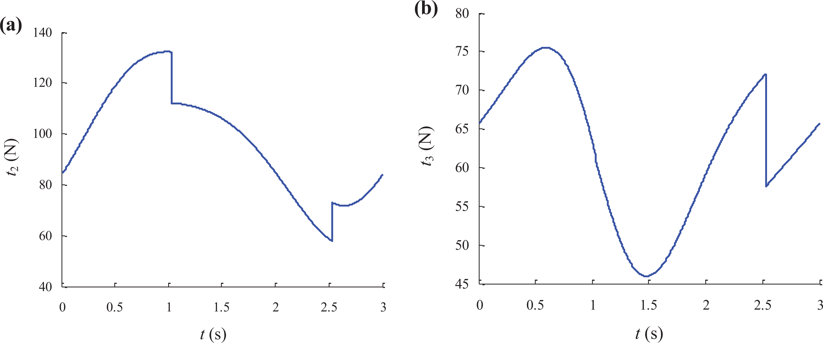
Changing tension curves of wires in the second planning strategy. Changing curve of the tension of (a) wire 2 and (b) wire 3.
At this moment, the fluctuation parameters of wire tension are

(
By comparing the fluctuation parameters in the two planning strategies, we could find
In addition to the external output force, the structural layout of the wires can influence the fluctuation of wire tension. After the external output force is determined, the fluctuation of wire tension can be improved by moving the position planning of the rigid chain.
Conclusion
According to the characteristics of the lower limb rehabilitation robot and the requirements of lower limb rehabilitation training, a model of a rigid–flexible coupled rehabilitation robot of lower limbs is conducted. The model could improve the performance of wire tension in the completely restrained wire-driven parallel robot while satisfying its configuration. The D-H method and the influence coefficient method are employed to build a kinematic model of the robot system. Two rigid chain planning strategies are proposed. D’Alembert’s principle is applied to establish the dynamic model of the system. The fluctuation parameter of wire tension is introduced to appraise the driving characteristic of the wires. This research lays the foundation for position servo control of the robot system and driving characteristics. The expected movement (normal gait trajectory) of the knee joint and hip joint is taken as the control target. The motion state of the system and the characteristics of the driving wires are simulated and analyzed. The result indicates the validity of the structural layout of the driving wires and the original state of rehabilitation training. The fluctuation parameters of wire tension prove that the planning strategy with the angle bisection method is better in normal gait trajectory.
In this article, two kinds of planning strategies are proposed, which are related to the trajectory of the motion and the wire force. In the normal gait, it proves that the first planning strategy is better than the second. However, due to the different conditions of measuring the pros and cons of different strategies, the proposed strategy may not be optimized, which will be discussed in the future study.
Footnotes
Declaration of conflicting interests
The author(s) declared no potential conflicts of interest with respect to the research, authorship, and/or publication of this article.
Funding
The author(s) disclosed receipt of the following financial support for the research, authorship, and/or publication of this article: This project is supported by the National Natural Science Foundation of China (51405095), Postdoctoral Scientific Research Fund of Heilongjiang (LBH-Q15030), and Fundamental Research Funds for the Central Universities (HEUCF170701).