
Abstract
Introduction
Wearable robotic exoskeletons offer the potential to move gait training from the clinic to the community thereby providing greater therapy dosage in more naturalistic settings. To capitalize on this potential, intuitive and robust interfaces are necessary between robotic devices and end users. Such interfaces hold great promise for research if they are also designed to record data from the robot during its use.
Methods
We present the design and validation of an open source graphical user interface (GUI) for wireless operation of and real-time data logging from a pediatric robotic exoskeleton. The GUI was designed for trained users such as an engineer or clinician. A simplified mobile application is also provided to enable exoskeleton operation by an end-user or their caretaker. GUI function was validated during simulated walking with the exoskeleton using a motion capture system.
Results
Our results demonstrate the ability of the GUI to wirelessly operate and save data from exoskeleton sensors with high fidelity comparable to motion capture.
Conclusion
The GUI code, available in a public repository with a detailed description and step-by-step tutorial, is configurable to interact with any robotic device operated by a microcontroller and therefore represents a potentially powerful tool for deployment and evaluation of community based robotics.
Introduction
Gait rehabilitation remains a major challenge in pediatric populations. Clinic-based robotic assisted gait trainers (RAGT) have become more prevalent in the past decades for use in pediatric populations. 1 Yet, systematic reviews of RAGT do not provide evidence to support improved outcomes.2,3 Potential reasons for the underwhelming results from these studies are the relatively limited intervention schedules (2–5 sessions per week, 25–60 minutes each, for up to 6 weeks)3,4 and the absence of dynamic adaptable control systems that challenge the user and ensure active participation in rehabilitation. 4 Wearable exoskeleton technology offers the potential to address these shortcomings by providing daily bouts of overground gait training tailored to the individual user. As an example, we previously developed a pediatric knee exoskeleton that alleviates crouch gait in children with cerebral palsy by using precisely timed knee extension assistance to dynamically change posture. 5 A recent cohort study in children as young as 5 years of age showed that this approach was safe and well tolerated, and knee extension was significantly increased and knee extensor muscle activity was maintained during overground walking with the exoskeleton. 5 Our recent efforts have expanded the assistive capabilities of the exoskeleton to include three different options; constant torque assistance, 5 target trajectory tracking with impedance-based control, or real-time adaptive control.6,7 The overall goal of our research is to develop a wearable exoskeleton to provide gait training optimized for each individual that can be performed outside of the laboratory or clinical setting. In general, wearable pediatric exoskeletons are an active area of research with several recent studies in addition to our own demonstrating new systems designed to improve pediatric gait and facilitate gait training in a wide variety of movement disorders.4,8,9
While much attention to date has focused on designing the optimal method of human-machine interaction between the exoskeleton and user, 10 comparatively little effort has been undertaken in design and implementation of an intuitive user interface for operating these devices in rehabilitation and community settings. A user interface serves as the primary means of communication between engineers, clinicians, and ultimately end-users and the robotic exoskeleton. The interface can serve a variety of functions, including device powering on/off, adjusting device settings and mode of operation, wirelessly recording and displaying data, and reporting user performance metrics including progress on rehabilitation goals. Graphical User Interfaces (GUIs) have become commonplace in everyday life and for human-robot interactions. Most websites, phone apps, or electronic kiosks are designed with a visual interface that allows for intuitive yet comprehensive control. User interfaces have also become an integral component of commercially available rehabilitation robotic technology. One such example is Ottobock’s Cockpit 11 and Setup 12 Applications, available for phone and tablet devices. This design approach includes development of separate interfaces for each type of user: the ‘Cockpit’ application for the end-user and a ‘Setup’ application for clinicians to adjust the technical settings of the devices. Yet despite the commercial use of such interfaces and their obvious value for human-robot interaction, little literature exists regarding how to design such a system. To our knowledge, there are no existing paradigms that dictate guidelines or examples of designing an interface for a wearable rehabilitation device.
Equally valuable to rehabilitation engineering research are open source tools that can be easily adapted for different technologies and research purposes. Open source tools are used in many areas of rehabilitation, such as electroencephalography (EEGLAB 13 ), human biomechanics (OpenSim 14 ), and even prosthesis design (OpenBionics 15 ). Other more general open source software and hardware tools enable common engineering tasks for rehabilitation applications, such as Lab Streaming Layer 16 (LSL), which allows the integration of data from multiple sources onto a single platform, Unity game engine, 17 which enables creation of custom virtual environments that incorporate and respond to a person’s movements, and Arduino, 18 which provides integrated open source electronics for sensor measurements and device controls. Increasingly these open source tools have been leveraged to create novel devices and systems that use signals from body-worn and/or biological sensors to implement closed loop robotic control for training or exercise, i.e., to facilitate neurorehabilitation. Some examples, in addition to our own and others’ microcontroller-based lower extremity exoskeletons6–9 include wearable exoskeletons for assistance and rehabilitation of hand function, 19 EEG-based brain computer interfaces for controlling functional electrical stimulation (FES),20,21 robotic systems that provide biologically-based haptic feedback for motor skill development and training,22,23 and frameworks for developing 3 D interactive games for rehabilitation exercise. 24 Whereas these systems leverage open source tools for operation, control and user-interaction, and some even make their architecture available for others to use, 22 no open source graphical user interfaces exist specifically to facilitate serial or wireless communication of control parameters, operational commands or data logging for an open sourced, microcontroller-based rehabilitation robot.
The goal of this project was to design an interface capable of wirelessly communicating with and receiving data from our wearable robotic exoskeleton using open source software. Similar to previous commercial systems, this interface was developed with two distinct components: a desktop (or laptop) interface for clinicians and engineers, and a phone interface for end-users wearing the exoskeleton. A secondary goal was to establish an open source resource for future graphical interface design in rehabilitation by making all source code for the GUI available through a public software repository so that it can be adapted for use with other devices.
Methods
Design requirements
The initial interface for our pediatric exoskeleton, or P.REX, 6 utilized a prompted command line interface. While effective in the laboratory setting, this approach is not robust to human error and required many entries (approximately 24) to initiate exoskeleton operation. Further, data transfer and communication were via a wired connection and two communication streams were necessary, one for each leg. Based on this experience, we established general design requirements for a GUI that were divided into two main areas: the interface component, which describes design of the front-end user interface, and the communication and data handling component, which encompasses the back-end software that passes data between the device running the GUI and the robotic exoskeleton (Table 1).
Design requirements for P.REX graphical user interface.

In addition to these inputs, a more abstract design goal was to limit the user’s scope to only that information necessary for them to control the device as desired or as predetermined by the study or clinical team. By only enabling certain features to the user at certain times, the interface is more intuitive and more resistant to user error. For instance, when using a constant torque controller, the number of torque assistance levels (i.e., setpoints) the user needs to set depends on the state machine chosen. Therefore, if a two state machine is chosen, the user is presented with two torque setpoints. If a three state machine is chosen, three setpoints are presented. The buttons to start and stop data collection with the exoskeleton can be similarly managed; these buttons are disabled until the user has entered all required settings, at which point the start button is enabled. After the exoskeleton is activated the start button is disabled and the stop button is enabled. This limitation of the user’s scope makes the desired action more intuitive and also helps ensure that certain actions are only taken at the appropriate point and in the appropriate way in the communication process.
Design environment
P. REX (Figure 1(a)) is designed to provide individualized assistance for knee extension during walking. Because it is a pediatric exoskeleton, the individual who dons the exoskeleton may be different from the person who operates the GUI (for example, a young child and caretaker, respectively). In particular, the current GUI design is targeted for use by a trained operator such as an engineer or clinician, although in future versions that function may be served by a caretaker as well. Therefore, for the remainder of the manuscript, the person donning the exoskeleton is referred to as the “wearer” and the person operating the GUI is termed the “user”. In future iterations, it may also be possible for the wearer and the user to be the same individual.

Overview of a pediatric knee exoskeleton (P. REX). (a) The device incorporates a custom actuation assembly and embedded electronic control system mounted on the lateral side of the leg. (b) The hierarchical real-time control loop running in the embedded microcontroller during exoskeleton operation. The diagram in the top right inset shows the 5 state finite state machine. Red blocks are states where extension assistance can be provided. The diagram in the bottom right inset shows the feed-forward and feedback closed loop control for torque delivery.
The exoskeleton controller (Figure 1(b)) has been previously designed.5–7 The exoskeleton has two operational modes: Standby Mode and Walking Mode. In Standby Mode, the goal is to be transparent to the wearer and therefore only minimal assistive torque is provided to compensate for device friction and inertia but no walking assistance is provided. In Walking Mode, the user can select from three different torque-based assistance strategies: 1) constant torque; 2) impedance-based control that tracks a target knee trajectory; or 3) real-time adaptive control. The exoskeleton control system is hierarchical (Figure 1(b)). At the top level, a finite state machine is implemented to parse the wearer’s gait cycle into as few as two states (stance phase and swing phase) or as many as five states (early stance, middle stance, late stance, early swing, and late swing). The settings for this finite state machine are individual-specific and therefore must be editable in the GUI design. In the second layer, a user must select one of the above 3 assistance strategies. Each strategy requires unique, wearer-specific parameters to be entered before the exoskeleton can function. For example, the constant torque controller provides different assistance levels within each gait phase, while the adaptive controller adjusts assistance as a proportion of the wearer’s estimated knee moment in real-time. 7 Each of these settings can be tuned based on wearer preference, and therefore need to be available as optional adjustments in the GUI. The lowest level of the controller utilizes a closed loop feedback and feedforward PID controller to deliver torque at the knee as specified by the control layers above it (Figure 1(b)). The exoskeleton control system was written in AVR-C using an Arduino Integrated Development Environment (IDE) (Arduino, Somerville, MA) to operate on a Teensy 3.2 microcontroller (PJRC, Portland, OR). The operating code includes two parts: First, a header file that contains definitions of variables and imports proper libraries; and second, a set of function files that carry out exoskeleton control strategies at each level of the control hierarchy and sensor monitoring. Each leg of the exoskeleton uses an independent microcontroller running the same version of the control code.
The desktop P.REX GUI was designed for engineers and/or clinicians in a research laboratory or clinical setting to interact with the control code running on the exoskeleton microcontrollers. The graphical components of the GUI were designed using the Tkinter library and the backend operation was programmed in Python 3.7.3 (Python, Wilmington, DE). The primary goals of this interface are to communicate operational settings of the exoskeleton closed loop control system running on the embedded microcontroller and to receive data from the exoskeleton to be stored on the computer running the GUI. The interface allows for communication in two ways: 1) using a wired connection between the USB serial port of the computer and the Teensy Microcontroller embedded in the exoskeleton electronics or 2) using a wireless Bluetooth serial connection facilitated by the BlueSMiRF modem (SparkFun Electronics, Niwot, CO) connected to the microcontroller (Figure 1(a)). The wired USB and Bluetooth communications require installation of a serial module (pyserial) and Bluetooth module (PyBluez) to allow Python code to access the host machine’s serial and Bluetooth communication resources, respectively. The Bluetooth modems stream data to and from the desktop computer using an USB Bluetooth dongle (ASUS, Taipei, Taiwan). Two BlueSMiRF Bluetooth adaptors, one for each exoskeleton leg, were connected to the dongle using a client-server relationship.
The GUI was also designed to be modular such that it can interface with any system that runs real-time control code from a microcontroller with embedded Bluetooth modem. For example, we have also developed a controllable electrical stimulation unit to be used in tandem with the exoskeleton. We have therefore incorporated space in the desktop GUI to specify the control parameters of the electrical stimulation, including the desired gait phases in which electrical stimulation should be on or off, and the amplitude, pulse-width, and frequency of stimulus.
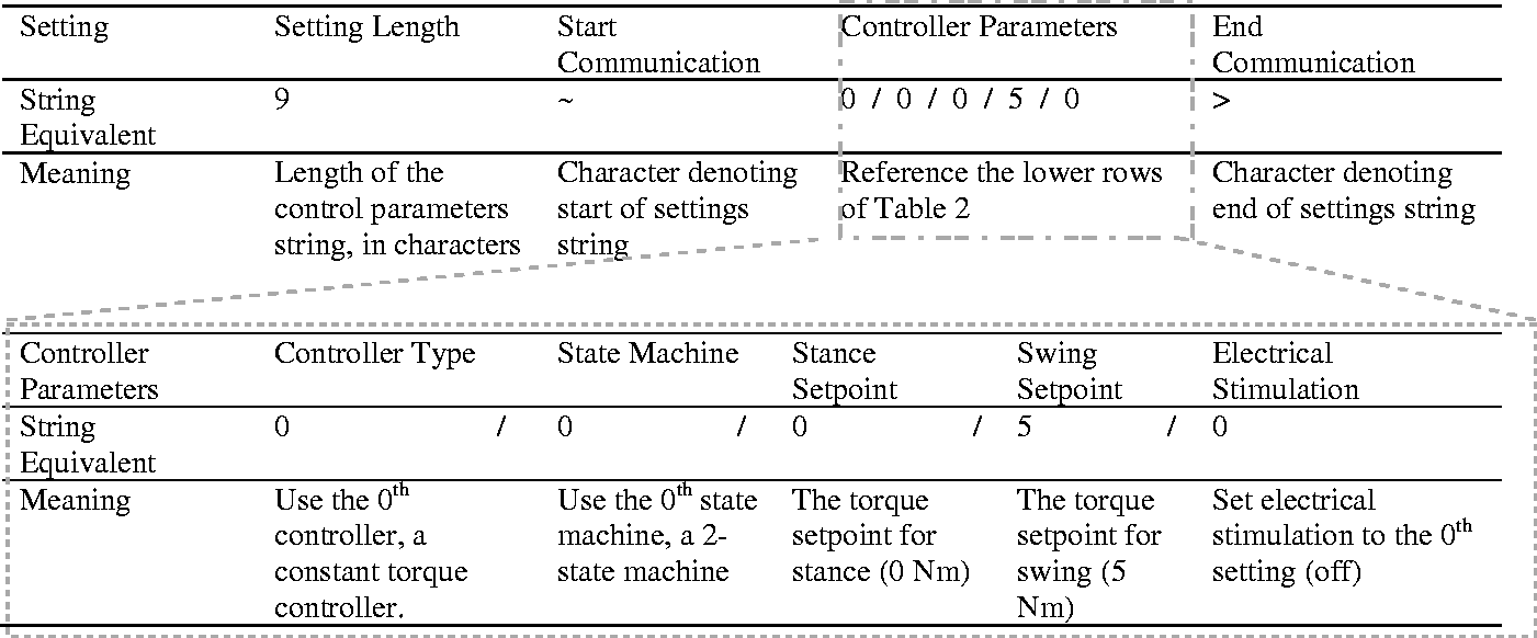
The GUI facilitates bi-directional communication between the host desktop computer and the embedded microcontrollers running the code that controls the exoskeleton in real time. Custom functions were created to package the control inputs entered by the user in the GUI into a single communication string that is then sent to the embedded exoskeleton code, where a second function parses the inputs from the GUI and integrates them into the real-time control system. These customizable functions are intended to allow use of the GUI with any robotic application equipped with the requisite hardware. A string was chosen because it provides a constant format that can be used for any kind of ASCII symbol, and only requires a marginally greater amount of data space than the integer or double data types in our context. This string (Table 2) contains settings separated by a character delimiter (the forward slash symbol, “/”,) with separate characters indicating the start (“∼”) and end (“>”) of the settings. The exact string format and length is flexible and determined by the exoskeleton operational settings that have been selected in the GUI. For example, the controller type (constant torque, adaptive, or impedance-based trajectory tracking) and finite state machine (2–5 states) selections will impact the number of control-specific parameters that must be specified in the GUI. An example of a GUI generated communication string is shown in Table 2. The string can also contain other information that is internally generated, such as the total length of the string itself and the origin of the settings (i.e., a desktop or phone) which are used by the embedded code of the exoskeleton to unpack the string, apply the updated control settings, and send communication back to the GUI. If the user desires, the exoskeleton code will save the updated settings to the EEPROM (non-volatile data storage) in the microcontroller which can be accessed by other GUI based terminal devices such as a phone.
Example string format for communication of controller specific parameters.

During exoskeleton operation, all sensor data received by the desktop GUI is sent to Lab Streaming Layer (LSL), an open source cross-platform synchronization tool. 16 Sensor data are formatted as floating point (single precision) data when read by the microcontroller and sent to LSL. Lab Recorder, an interface for LSL, is opened automatically as a sub-process by the Python GUI. Once data are received by LSL, any computer connected in the network can access it. Due to inherent speed limitations of graphing in Python, a separate graphing application was designed in Unity (Unity Technologies, San Francisco, CA) for data visualization during a trial. This application is also opened as a sub-process by the Python GUI and automatically calls data from LSL for visual display. A complete schematic of the system architecture is presented in Figure 2.
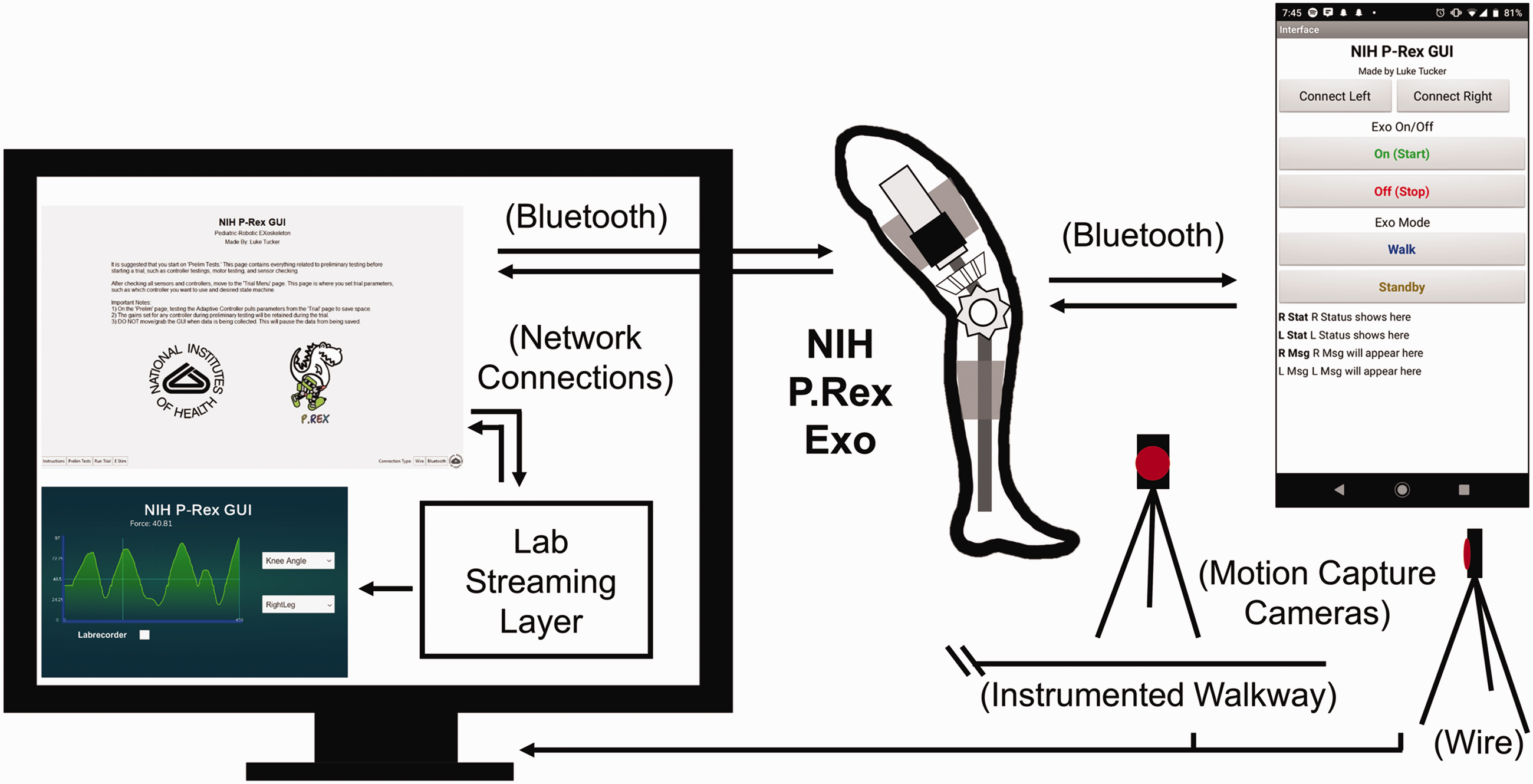
P.REX GUI system architecture: left, desktop interface; center, P.REX; top right, phone interface; bottom right, commercial data collection instruments. All components on the computer screen constitute the desktop GUI. Data are sent over Bluetooth to the Python application, shown on the top left of the computer screen. The Python application sends exoskeleton sensor data in real time to LSL to be time-stamped and saved. A separate (optional) plotting application shown at the bottom left of the computer screen pulls data in real time from LSL. Time series data are saved with LSL and can be compared with motion capture and force plate data collected in the laboratory. The exoskeleton can also be controlled over Bluetooth with a phone interface, shown in the top right.
Validation test
We performed benchtop tests to evaluate the reliability, speed, and systematic delay of the desktop GUI. The exoskeleton was secured to an extruded aluminum frame and manipulated by hand to simulate knee flexion and extension similar to that experienced during human walking. A motion capture system (VICON, Oxford Metrics, UK) collected kinematic data from the exoskeleton to externally calculate knee angle as the ground truth. Four reflective markers were attached to the thermoplastic shells of the exoskeleton near the lateral hip, medial and lateral knee, and lateral ankle centers of rotation. The posterior angle between the thigh and shank segments was used to calculate knee angle from the motion capture system as a reference for the exoskeleton sensors. Data from the on-board sensors (three sensors per leg: knee joint torque sensor, force sensitive resistor, and knee joint angle from the motor encoder) were collected for angle comparison and to evaluate the GUI data streaming and saving functionality.
During data collection, each system (motion capture and P.REX GUI) was started independently and data were saved in the respective software. To test the efficacy, reliability and sampling rate of the desktop GUI interface, we sent a series of twenty square wave pulses over a wire to the P.REX and to a commercial DAQ unit (National Instruments, Austin, TX) in the motion capture system to serve as a reference. During the experimental trial, the motor of each leg was back driven by hand to increase computational effort of the exoskeleton’s operating system. The P.REX GUI collected the triggered pulses and data from the exoskeleton onboard sensors over the Bluetooth wireless connection and sent them to LSL to be timestamped and saved. Additionally, an incremental counter was encoded into the main sampling loop of the Python GUI to measure the desktop GUI sampling rate. This counter incremented during each iteration of sampling from the exoskeleton and was output as a separate channel to LSL. The sampling rate of the desktop GUI, which is different from the sampling rate of the embedded microcontroller operating the exoskeleton, was determined from the mean and standard deviation of the time between samples from this counter. Signals collected by the exoskeleton GUI over Bluetooth and the Vicon motion capture system were synchronized in post-processing using MATLAB (Mathworks, Natick, MA) by aligning the leading edge of the first square wave pulse in each data set. The time delay between the GUI and DAQ system was then quantified by the mean and standard deviation difference in time between the subsequent 19 pulses. The data sampling rate for exoskeleton was computed from the mean of the interval between LSL time stamps of the exoskeleton sensor data. Both legs of the exoskeleton were set to send data at 100 Hz which matches the commercial DAQ for motion capture set to sample at 100 Hz.
Results
GUI design
The GUI design splits the interface between three pages; “instructions”, “preliminary testing”, and “run trial” pages. The instructions page is the first page displayed to the user and gives guidelines for how to use the GUI (Figure 3(a)). The preliminary testing page (Figure 3(b)) incorporates all elements of the system that would need to be checked before running a trial, such as streaming live sensor data or testing control modes by streaming data from each exoskeleton in “Left Leg Output” and Right Leg Output” consoles. For example, if the Potentiometer button is pressed, the bits value, voltage value, and corresponding knee angle values from both legs will be displayed and updated in real-time in the corresponding output console as shown in Figure 3(b). The “Universal Control Parameters” frame sets low level motor PID gains. The “Motor Parameters” frame allows diagnostics of the low level feedback control for each leg by testing constant, ramped, and sine-wave torque outputs. The motor performance can be visually checked in real-time by pressing the Motor button in the “Sensor Checking” frame, which then plots the set point and actual torque in the corresponding output console for each leg. Similarly, the “Torque Control Parameters”, “Impedance Control Parameters” and “Speed Control Parameters” frames allow diagnostic testing of these motor control modes that can be checked visually by pressing the corresponding button (Torque Controller, Impedance Control, or Speed Control) in the “Sensor Checking” frame. The Adaptive Control button displays motor output for a previously developed controller that estimates user effort and is hard-coded into the exoskeleton microcontroller. 7 The real-time reading from any sensor can be displayed in the Right and Left Leg Output windows by clicking a corresponding sensor button in the “Sensor Checking” frame. The potentiometer requires calibration each time the user dons the exoskeleton and the “Potentiometer Parameters” frame allows the user to input the sensor reading of each leg at two knee angles: 0 degrees (leg straight) and 90 degrees (knee flexed so thigh is perpendicular to the shank) to complete this calibration.

The P.REX GUI interface. (a) Instruction page. (b) Preliminary testing page including windows for live streaming of data from exoskeleton sensors. (c) Run trial page, including controls to start and stop data collection, and windows for live streaming of data from exoskeleton sensors and controllers. (d) Electrical stimulation page; an optional (exemplar) system that can interface through the GUI architecture via the addition of a tab in the GUI interface.
The run trial page (Figure 3(c)) allows the user to activate the desired assistance strategy and finite state machine, adjust the settings to the selected control modes, and enable collection, streaming and saving of exoskeleton data. After the controller, state machine, and data collection settings have been entered by the user, the upload settings button can be pressed, causing the GUI to create and send the aforementioned string-based command to the exoskeleton. After receiving the string, the embedded exoskeleton control code parses it and assigns the appropriate parameters in the real-time control code. After uploading settings on the run trial page, the ‘Start Trial’ button becomes active in the Data Collection Options frame (Figure 3(c)). The ‘Data Collection Options’ frame was customized for the experimental workflow in our laboratory with the exoskeleton and therefore includes several settings that are frequently adjusted prior to and/or during a data collection trial including: turning electrical stimulation on/off, toggling between exoskeleton Standby and Walking modes, adjusting the left and right FSR thresholds that dictate whether each foot is on or off the ground (normalized to the mean FSR value during stance), adjusting the trial number, sending new controller/sensor settings to the exoskeleton, and saving those settings. After the trial is started, the ‘Start Trial’ button automatically inactivates and the ‘Stop Trial’ button activates. When pressed, the ‘Stop Trial’ button ends data streaming from the exoskeleton and deactivates the motor. After the ‘Stop Trial” button is pressed, this button is replaced by a ‘Continue Trials’ button and the ‘Finish Trials’ button activates as well (Figure 3(c)). If the ‘Continue Trials’ button is pressed, the user will go through start/stop trial with the same settings. If the ‘Finish Trials’ button is pressed, the user can configure and upload the new settings and then restart the above start/stop/continue trial process.
The Run Trial page also incorporates other settings important to exoskeleton operation. The ‘Universal Controller Parameters’ subsection allows the user to tune the lower-level PID gains before any given trial. The PID gains are tuned manually for each exoskeleton setup, so this feature is especially useful when a first-time wearer walks with the exoskeleton. The E Stim Options subsection allows the user to choose electrical stimulation be on or off during the stance and/or swing phases of the gait cycle. This feature is intended to work with a separate controllable electrical stimulation unit that contains its own embedded microcontroller. (The electrical stimulation waveform parameters are specified on a separate page of the GUI as shown in Figure 3(d), located under ‘E Stim’ in the bottom left navigation menu).
The GUI allows for a robust workflow (Figure 4) for P.REX operation. The exoskeleton is first donned by the wearer and secured using straps to the custom-fit thermoplastic shells on each leg. The exoskeleton is then connected to a power supply, either from a lithium-ion battery or a DC power supply for in lab use. Turning the exoskeleton on provides power to all on-board electronics, including the microcontroller and the BlueSMiRF Bluetooth module required for communication with the desktop GUI. Concurrently, the GUI can be started on a desktop computer by double-clicking the Python script, automatically displaying the Instructions Page of the GUI, Lab Recorder, and the separate plotting application to the user. Before proceeding, the user should follow the instructions in Lab Recorder to initiate data saving via LSL. All data from each trial are saved in the Extensible Data Format (XDF) and the filename can be specified in Lab Recorder or alternatively one can be automatically generated. Once the exoskeleton is powered on and the GUI has been activated, the exoskeleton and GUI can be paired either over wire or Bluetooth by clicking either the ‘Wire’ or ‘Bluetooth’ button in the bottom right corner of the Instructions page. A sub menu appears to enter the MAC address (Bluetooth) or serial communication port (wire) before a ‘Connect’ button is activated to pair with the exoskeleton. This step also provides a layer of security by ensuring the GUI can only connect to the intended robotic device.

The P. REX GUI operational workflow. The top diagram shows operational sequence for the GUI user and P.REX wearer. Dashed boxes and lines represent optional steps not required. The bottom inset displays the communication between the python GUI and P.REX Arduino controller in response to GUI user input, including formatted strings and trial numbers from the GUI to the P.REX and handshake signals (symbols: ‘$’,‘, [comma]’, ‘@’, and ‘^’) sent from the P.REX back to the GUI to confirm receipt of a command.
After pairing, the user can move to the Preliminary Testing Page by clicking the ‘Prelim Page’ button in the bottom left corner. This page is optional and allows the engineer or clinician operating the GUI to ensure that all of the hardware on the P.REX is operating correctly. For instance, to check that the potentiometer is well-tuned to the true knee angle of the subject, the green ‘Potentiometer’ button in the ‘Sensor Checking’ submenu can be pressed, streaming live data from the potentiometer to the ‘Left Leg Output’ and ‘Right Leg Output’ displays. As the person wearing the exoskeleton flexes and extends his or her knee, the engineer or clinician operating the GUI can measure the wearer’s knee angle and ensure that the potentiometer is mapped to an equal value. If the potentiometer needs to be tuned, the engineer or clinician can position the wearer’s knee to 0 and 90 degrees, record the raw bit value of the potentiometer from the ‘Left Leg Output’ and ‘Right Leg Output’ displays, and input them under the ‘Potentiometer Parameters’ submenu. By clicking ‘Set Pots,’ each potentiometer is tuned to the true knee angle of the patient. Similar tests can be performed for the force-sensitive resistors, the motor encoders, or torque sensors.
After checking the hardware of the exoskeleton on the GUI, the Run Trial page of the GUI can be used to prepare the state machine and controller modes of the exoskeleton and activate a controller mode to provide assistive torque to the wearer. The page is displayed by clicking the ‘Run Trial’ button in the bottom left corner of the display. First, the engineer or clinician must choose which assistance type to use, either constant torque, impedance trajectory, or adaptive control. If using the constant torque controller, the user then chooses which state machine to use, ranging from the 2 to 5 as previously described. These operations are accomplished by selecting the appropriate radio buttons under the ‘Controller Options’ submenu. Depending on the control mode chosen, the GUI operator can then move to the respective submenu, either ‘Impedance Controller,’ ‘Adaptive Controller,’ or ‘Constant Torque Controller.’ The value of the controller settings in each submenu depends upon the controller chosen. A separate algorithm based on internal knee moment prediction determines the settings of the adaptive controller 7 ; the impedance trajectory and constant torque controller settings are individual-specific and can be adjusted in the GUI. Settings for these controllers are typically determined based on preliminary clinical analysis and observation as described in our previous work. 5 After entering the settings for the chosen controller mode, the user selects whether or not to use electrical stimulation during each gait phase by selecting the boxes under the ‘EStim Options’ submenu. Lastly, the engineer or clinician uploads the settings to the exoskeleton by selecting ‘Upload Settings.’ This button sends the string of settings to the exoskeleton, which is automatically parsed by the exoskeleton’s operating system. After receiving a confirmation message from the exoskeleton, the engineer or clinician can select ‘Start Trial’ to engage the motor of exoskeleton. The P.REX initializes into frictionless Standby Mode, allowing the wearer to walk without resistance or assistance from the exoskeleton. The user can toggle the ‘Mode’ radio button to ‘Walking,’ at which point the exoskeleton monitors the user’s gait characteristics and applies a corresponding torque as dictated by the chosen control mode. Once a trial is initiated, all data are streamed in real-time to LSL, where it is time stamped and saved on the GUI desktop. To disengage the motor and end a trial, the user can select the ‘Stop Trial’ button. This automatically places the P.REX back into Standby mode and the ‘Stop Trial’ button changes to ‘Continue Trials’ button. The user can then increment the trial number to activate the ‘Continue Trials’ button, and collect more data using the same controller settings (Figure 4(b)); the process can proceed as the user alternatively presses the Stop Trial and Continue Trial buttons. The user can terminate an experiment by pressing the ‘Finish Trials’ button, at which point the assistance mode can be modified, or the user can return to the Preliminary Testing page to adjust sensor or controller settings (Figure 4).
The GUI also allows for a simple workflow when testing the exoskeleton without a user wearing the exoskeleton. These tests are often desirable to determine the characteristics of each control mode6,7 and when troubleshooting issues with the onboard electronics of the exoskeleton. In this workflow, the P.REX and GUI are turned on and paired just as if a user was wearing the exoskeleton. Once connected, all testing of the exoskeleton can be performed using the ‘Preliminary Testing’ page. To characterize the actuator performance during benchtop testing, the user can command the motor with three different waveforms of current; a constant current, a ramp to a current, or a sinusoidal current. These options are selected from the ‘Motor Parameters’ sub menu and the test is started when the user clicks the green ‘Motor’ button under the ‘Sensor Checking’ sub menu. The sensors on each leg of the exoskeleton can also be checked and tuned from the preliminary testing page.
A scaled-down version of the desktop interface was implemented as a mobile app. This was designed for use by the wearer and/or their caretaker, and therefore incorporates a simpler design with less features. The mobile app component was designed using the MIT App Inventor to operate on Android devices. This App is used only to start or stop a trial and turn the current controller on (‘Walking Mode’) and off (‘Standby Mode’). Use of the mobile app interface requires a more sophisticated user to specify all settings using the desktop GUI. Those settings are saved to the EEPROM of the Teensy on each leg of the exoskeleton and are then called by the phone interface. Therefore, the phone interface incorporates only four buttons: ‘Start,’ ‘Stop,’ ‘Standby,’ and ‘Walk’ (Figure 5). The start button turns the control loop on and automatically puts the exoskeleton into Standby Mode. The walk button begins motor actuation according to the higher level controller saved from the desktop GUI. The stop button disengages the motor and stops a trial.

A separate phone interface was developed in the MIT App Inventor. This interface calls settings previously saved by the desktop GUI and provides a simple method by which a wearer or their caretaker could control the exoskeleton for community ambulation.
Validation results
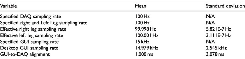
Table 3 presents the results from the exoskeleton validation tests. Both legs of the exoskeleton communicated with the host computer and GUI at almost exactly 100 Hz. The slight deviation is most likely due to the accuracy of the built-in timers on the microcontrollers. Additionally, the desktop interface operated at approximately 15 kHz, far above the exoskeleton sampling rate. For this reason, the signals collected by the commercial DAQ unit and by the desktop interface aligned almost exactly. The close alignment between the simulated knee angles further emphasizes the signal fidelity of the interface (Figures 6 and 7). During data collection, the Unity application was successfully able to display live data streaming from the exoskeleton.
System characterization by pulse alignment.

Motion capture and exoskeleton angle measurement comparison (top, left leg; bottom, right leg). Data were collected from the encoder of each leg of the P.REX (blue) and overlaid onto knee angle as collected by a commercial motion capture system (red). This comparison shows that the communication protocol is robust and comparable to commercially available systems at the specified sampling rate (100 Hz).

P.REX measurement of torque and controller state during simulated walking. During data collection, each leg of the exoskeleton was manually back-driven by hand to maximize the computational load on the embedded microcontroller. The torque setpoint, measured torque values, and finite state determined by the P.REX controller were accurately collected by our data streaming protocol. The system was not attached to a support when operating by hand, which accounts for oscillations.
Discussion
The desktop interface allows for complete, robust control of the exoskeleton and accurate data collection in the laboratory. Our previous approach 6 was a command line interface that was not robust to human error, provided no visual feedback of current settings, and required approximately 24 separate entries to prepare the exoskeleton for use. The GUI presented here instead enables all settings to start the exoskeleton to be updated at the same time and then uploaded to the exoskeleton using a single button press. The GUI also facilitates synchronization of exoskeleton data with other modalities such as motion capture, force plates, electromyography (EMG), and electroencephalography (EEG) via LSL without relying on any proprietary third party software. Additionally, the GUI is able to interact with all of these systems using a network connection either over WiFi or ethernet router.
To our knowledge, this is the first published design of an operating methodology for a graphical interface with wearable rehabilitative robotic technology that also wirelessly time-stamps and saves data from the system. All source code is made freely available in a public repository (https://github.com/NIHFAB/PREX-GUI-FAB). Important dependencies to use our code include LSL, a Python 3.7.3 Interpreter, and Python libraries (time, tkinter, os, sys, pylsl, pyserial, subprocess, and PyBluez). These libraries can be installed using ‘pip install’, a package management system for Python, in the command line interface of the desktop computer. Detailed instructions for code installation, and a step-by-step tutorial, are available on the GitHub website and wiki page. Our code was tested on a HP EliteBook laptop running Windows 10 with an Intel® Core™ i7 7th Gen CPU processor and would likely require modification for Linux and Mac operating systems. Much of the underlying functionality of our source code could be adapted for use with another robotic device. The source code can be split into 5 main categories; 1) functions to construct settings strings, 2) functions to receive and parse data from the device, 3) higher level communication functions to send and receive data from another device, 4) a GUI class to construct a visual display and connect different visual features to the previous functions, and 5) functions to interact with external applications, such as sending data to LSL or calling our plotting application (Table 4). The source code can be adapted for use with virtually any robotic device by modifying key functions within each category. The general workflow for adapting the GUI is as follows. First, a new string format should be designed based on the device operational requirements, i.e., the control parameters that are required inputs of the device. New developers should create a logic diagram of the important operating features or editable inputs (in our case, these features are the controller modes and state machine and their associated parameters) and map which variables fall into each case of the operation of their device. Once each case is determined, a universal format similar to that presented in Table 2 can be designed. The functions that construct the strings (Table 4) should then be customized to package the inputs into the designed format to send the user inputs from the GUI to the microcontroller. Next, the functions that receive and parse data from the robot microcontroller should also be customized so the number of received data variables matches those sent from the microcontroller. Then, the GUI Class functions and associated tkinter widgets, which handle the text the user inputs into the GUI, should be customized so the visual display provides entry boxes, radio buttons or push buttons that correspond to the necessary inputs to be communicated to the microcontroller (i.e., the input values that will be sent via the custom designed string). These widgets can also be configured to display custom titles, instructions, comments, institutional logos or images on the GUI (Figure 3(a)). Finally, the functions that send data from the GUI to external applications, such as LSL for data-logging and timestamping, should be modified to match the outputs sent from the robot microcontroller. After the code is customized to handle the inputs and outputs of the new robotic device, the only other modification necessary is to ensure the MAC address(es) of the microcontroller Bluetooth modem(s) are updated in the code to match the hardware. Additional details and a simple example of programming the GUI to accept and send an arbitrary input from a user to a microcontroller are available in the GitHub wiki (https://github.com/NIHFAB/PREX-GUI-FAB/wiki). In addition to the python GUI code, the phone app could also be adapted to a different device using the IDE on the MIT App Inventor website (https://appinventor.mit.edu/).
P.REX source code function and classes.

GUIs for wearable rehabilitative technology are essential to deploying this technology in daily living and therefore present a powerful avenue for research in rehabilitation robotics. The most important feature of our interface is its ability to stream data in real time over a Bluetooth connection and timestamp those data for further analysis, allowing untethered gait training in the laboratory or at home. In the field of rehabilitation robotics, this functionality is key to monitoring device performance and user improvement over time. For one, it allows researchers to study human-robot interaction without the physical interference from wires. Such a method of accurately saving data in real time will also allow researchers to amass a large data base of operating characteristics on their device. In our context, this will allow our research group to analyze the performance of each aspect of our exoskeleton’s hardware (motor, motor drive board, torque sensor, and potentiometer) while testing the exoskeleton in a pediatric population. It will also enable the device to report user statistics without relying on external methods of collecting data, such as motion capture or inertial measurement units. One of our primary clinical populations is children with crouch gait, for whom an important clinical outcome metric is change in knee angle during gait. The ability to save data in real-time from the onboard potentiometer and motor encoder of the P. REX will allow us to track changes in knee angle during gait, enabling the device to be closely monitored during community ambulation without additional measurement hardware. The GUI source code in the repository can be altered to wirelessly log data from any sensor connected to a microcontroller (for an example, see step 4 of the tutorial on the GitHub wiki), thereby enabling its future use in community-based rehabilitation robotics research.
Although the GUI presented here was designed for modularity to enable its adaptation to and use with other robotic applications, several limitations warrant discussion. First, the software has several library dependencies and the compatibility of the software with future operating systems and hardware is contingent on continued compatibility of these dependent software packages. Second, although the GUI software in principle can be used to communicate with any microcontroller system containing an available and configurable Bluetooth or serial communication socket, it has only been evaluated using the Arduino platform on Windows. Third, the software was designed for implementation and use by engineers and therefore knowledge and understanding of Python coding principles is a prerequisite for using and customizing the software. Finally, the P.REX used for testing the GUI here includes an emergency stop button that cuts power to the robot in the event of abnormal or unexpected behavior arising from sensor, actuator or GUI malfunction; it is recommended that any wearable robotic device include this feature for user safety. Additionally, a few hardware and software requirements must still be met for community-based gait training with P.REX. Most importantly, a framework for privately sharing data from the exoskeleton in a home or community setting must be implemented. As currently constituted, the GUI saves data from the exoskeleton on the desktop (or laptop) running the GUI software. However, during actual deployment, it would be desirable to transfer these data from the computer running the GUI back to our institution. To accomplish this task, we recommend the development of an additional network communication framework to encrypt data to protect each wearer’s privacy, and then send those data over a wireless network to a server that can be accessed by the clinic or laboratory. A proposed system architecture for this modification is presented in Figure 8. Additionally, we plan to perform subject testing using this desktop GUI and the phone application to ensure it is intuitive for unfamiliar users. Finally, a second phone app that could be downloaded onto iOS devices will ultimately be implemented.

Proposed system architecture for community based deployment of P.REX GUI for home based gait training.
Footnotes
Acknowledgements
We would like to thank CodeNIH and Blynn Shideler for supporting development of the P.REX GUI.
Contributorship
DLD, TCB, and JC conceived the study. LAT, JC, LH and TCB researched literature and participated in engineering development. TCB, LAT, JC and DLD participated in experimental design. LAT and JC collected and analyzed data. LAT, JC, LH and TCB wrote the first draft of the manuscript and created figures. All authors reviewed and edited the manuscript.
Declaration of conflicting interests
The author(s) declared no potential conflicts of interest with respect to the research, authorship, and/or publication of this article.
Funding
The author(s) disclosed receipt of the following financial support for the research, authorship, and/or publication of this article: This work was funded by the intramural research program of the National Institutes of Health Clinical Center.
Guarantor
TCB.