
Abstract
The Paden–kahan subproblem is a simple and flexible method to solve the closed-form inverse resolution but limited by the geometrical structure of robots, which is very difficult to be kept because of processing and installation. Therefore, a closed-form solution on arbitrary configurations is an important issue in the field of robotic inverse kinematics. A novel second subproblem is firstly proposed in this study based on the product-of-exponentials model adapting to the two arbitrary axes without geometric constraints (parallel, vertical, disjoint, and so on). Furthermore, the algebraic methods involving the basic properties of the screw theory and Rodrigues’ rotation formula are employed for the solution, which makes the constraint equations of the second subproblem solvable for arbitrary configurations. This methodology can be applied to the inverse solutions of 5-degree-of-freedom robots that satisfies the Pieper criterion and can express the inverse solutions via two common formulas. Finally, the simulation and the real-world experiment demonstrated the accuracy of the method and the validity, respectively.
Introduction
The mapping relationship between the end effector and the joint angles of robots, referred to as a robot kinematics model, is very important in robot applications. 1 This relationship can be defined as forward or inverse kinematics, wherein the forward kinematics is to build the relationship in terms of the position and orientation of the end effector from the joint angles and can be easily determined by the link parameters and joint variables of a robot. Conversely, inverse kinematics (IK), which resolves the joint angles from the model based on the position and orientation of the end effector, is a nonlinear and configuration-dependent problem that may have multiple solutions. 2
As solving the IK problem is significantly complicated, a closed-form inverse solution is desirable because it offers fast computational speed and high precision. 3 However, robots must satisfy the Pieper criterion, which requires the paralleling of the three adjacent joint axes or the intersection of these joint axes at a single point. 4 Fortunately, most commercially available multi-joint robots satisfy this criterion. Additionally, there are several widely used methods to solve IK problems, such as Paul’s inverse transformation, 2 Pieper’s method, 4 and Paden–Kahan subproblems. 5 The first two methods are based on the Denavit–Harbenterg (D-H) model and require a large number of formula derivations and configuration-specific recalculations of solutions. 6 The Paden–Kahan method is based on the product-of-exponentials (POE) model, which decomposes a full manipulator into three classes of subproblems that can be easily solved, and every subproblem includes several types, and there are 28 types for three classes, 7 which consequently make the inverse solution to be easily obtained by assembling several subproblems according to the configuration. Evidently, the Paden–Kahan method is flexible, simple, geometrically meaningful, and numerically stable. 3,7 Moreover, because of these advantages, it can be widely applied in various research areas. 8 –11
Although it possesses the benefit of being more adaptable than other conventional methods, the types of existing subproblems are all based on the geometric relationships of adjacent axes such as intersecting, 3,7,12 parallel, 13,14 and different vertical surfaces. 15 However, in practice, the above relationships are hard to be kept during the process of machining and installing, and it limits the range of applicability of robots. In order to resolve this problem, a new second subproblem (new Sub-2) without geometric constraints is developed. New Sub-2 utilizes the new first subproblem (new Sub-1) to reduce the five IK solutions for 5-degree-of-freedom (5-DOF) robots into two formulas. It is important that this new method can be applied in other fields, such as semi-vehicle suspension systems 16 and 2-DOF quarter-car suspension systems. 17
The remaining sections of this article are arranged as follows: first, background knowledge on the aforementioned problem is presented in the form of a mathematical description of the second subproblem, properties of the screw theory, and two important lemmas. The subsequent section details the derivation process of the novel first and second subproblems. Next, the closed-form inverse solutions of the 5-DOF robots are provided. The succeeding section demonstrates the practicability of the first and second subproblems developed in this study by presenting analysis and comparative results of simulation and actual experimentation. In the final section, the significance of the results and future work is discussed.
Background knowledge
Mathematical description of the second subproblem
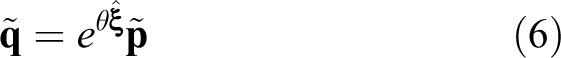
As shown in Figure 1, the second subproblem is defined as a rotation of

where

where

where

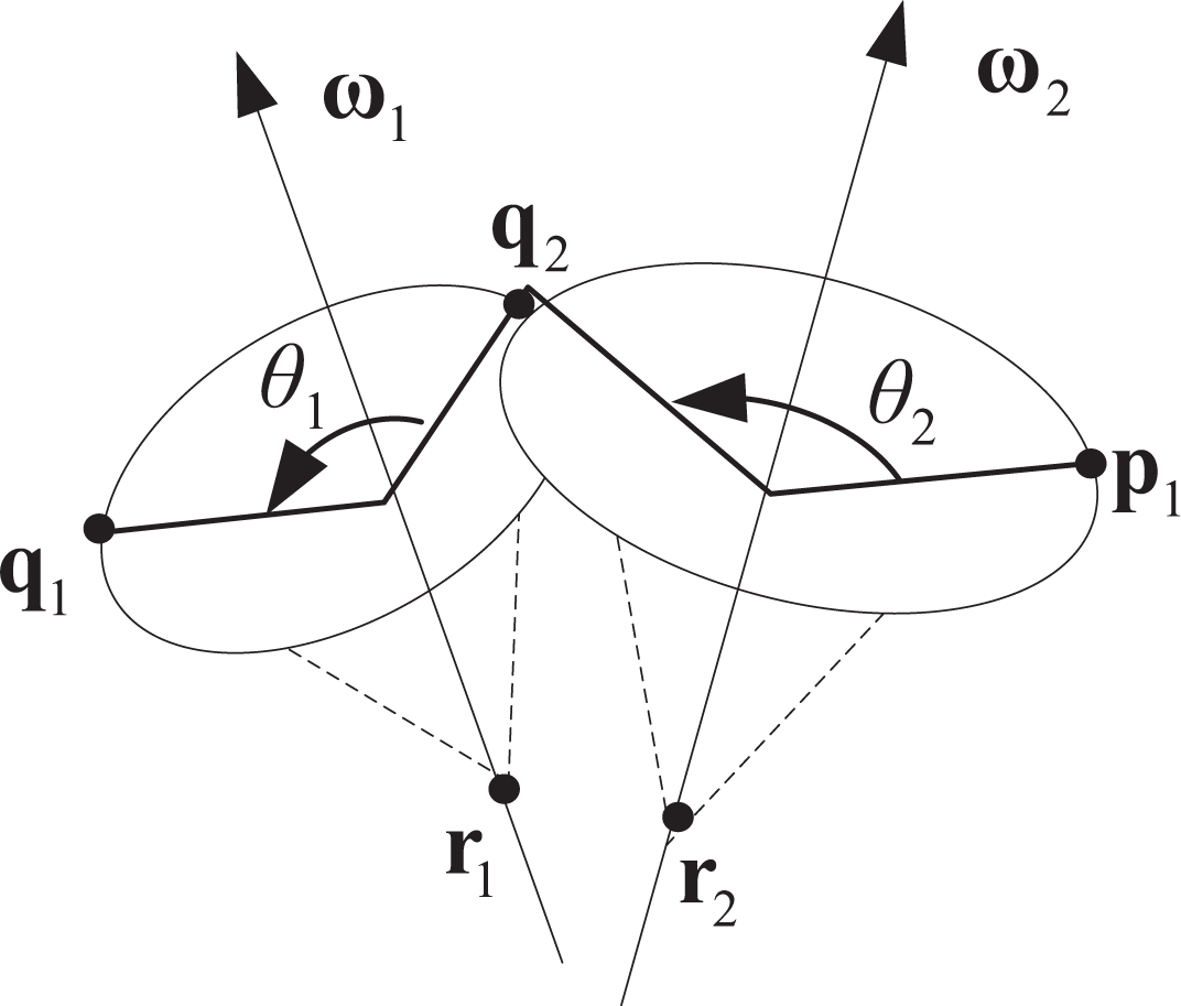
Second subproblem.
Two related lemmas
In order to facilitate the understanding of the derivation process of the novel subproblems, two important lemmas are provided here for application in a later section.
Lemma 1
If a vector

Lemma 2
Applying equation

Proofs of Lemmas 1 and 2 can be found in Appendix 1.
Calculation of novel subproblems
The existing methods can be applied in the robots with some special geometric relationship; however, the resulting expressions vary according to the robot configuration. Because of this, a general and simple expression is more practical in robot applications. Therefore, a novel method combining the geometric and algebraic methods is introduced, in which the explicit geometric relationship, such as the equidistant relationship before and after the rotation, is utilized to obtain the constraint equations, while the algebraic method involving the basic properties of the screw theory and Rodrigues’ rotation formula is used to resolve the equations.
Solving the new Sub-1 using algebraic methods
As can be ascertained from Figure 2

First subproblem.
Furthermore, according to Lemma 1

Then, substituting the Rodrigues’ formula for

where

Because
and
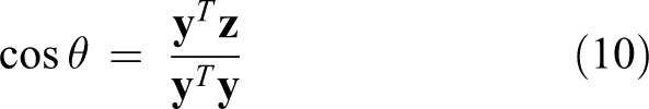
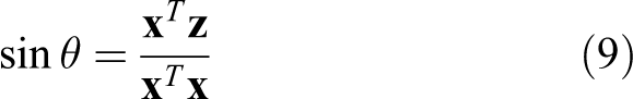
Thus, θ can be expressed as

This equation is new Sub-1.
Solving the new Sub-2 using algebraic methods
As illustrated in Figure 1, the distance between

Additionally, applying Lemma 1 yields

Then, substituting equation (13) into equation (12) yields the following

Squaring both sides of the above equation simplifies the formula to yield

where

According to Lemma 2, θ1 can be directly obtained, as shown in equation (16).

Because θ1 is constant, the value of
As expected, the above equation is adaptable to any case with two adjacent axes; however, it is important to note that the two points
Inverse solution of a 5-DOF robot
Figure 3 shows the structural diagram of a 5-DOF robot, including a shoulder joint, an elbow joint, and wrist joints, where the shoulder and elbow joints are two disjoint axes, and three joints of the wrist are intersecting; its POE model can be expressed as

where
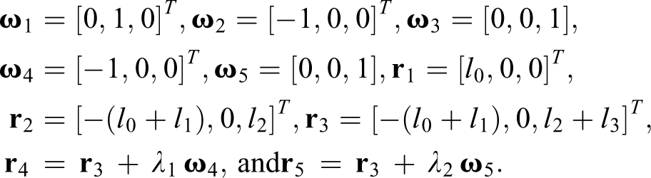
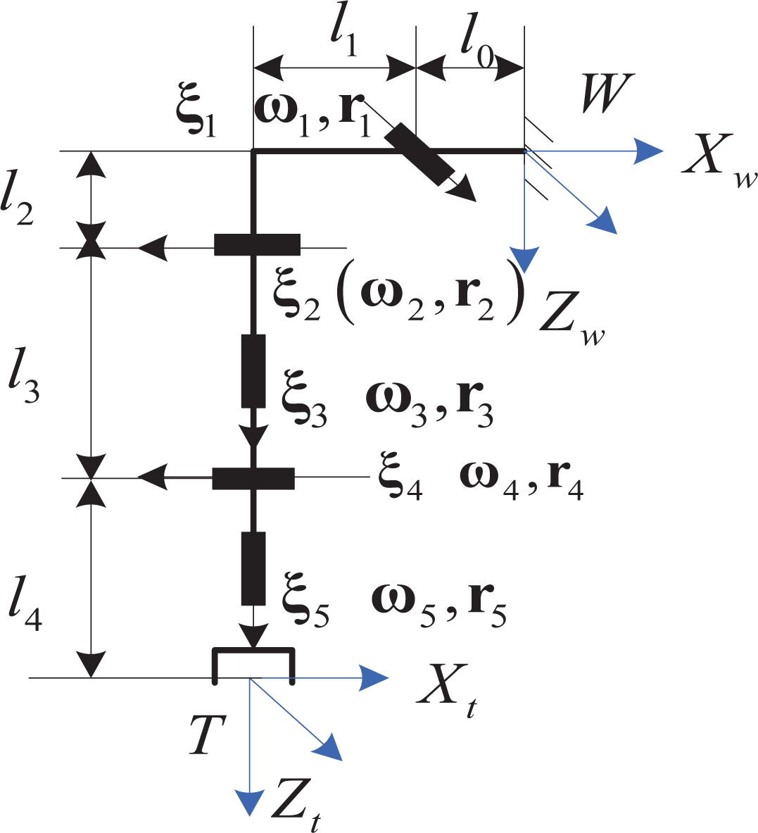
The structural diagram of a 5-DOF robot. 5-DOF: 5-degrees of freedom.
The initial posture can be expressed as

Suppose 1. Eliminate the three intersecting wrist joints by using POE equation reduction techniques. Let

As

where
2. Because θ1 and θ2 are known, equation (17) can be rewritten as

Setting

where
3. Substituting θ1, θ2, θ3, and θ4 into equation (17), gives

We can thus define a point

where


where
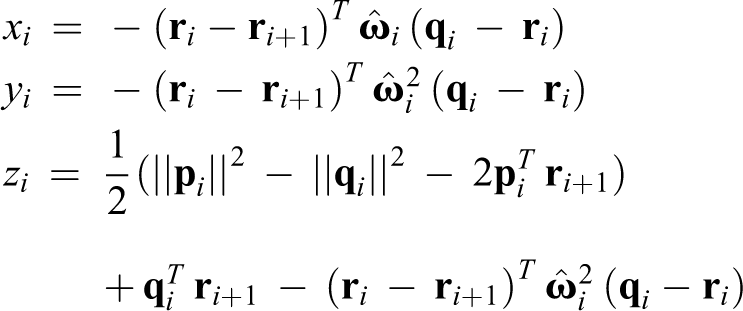

In these equations,
Actual and simulated experiments
In order to verify the correctness and validity of the proposed method, we apply the new Sub-1 and new Sub-2 in actual and simulated experiments.
Simulated experiment
The screw parameters of the 5-DOF robot illustrated in Figure 3 can be set as

Subsequently, we can obtain all joint angles for the above posture by solving equations (24) and (25). There are four groups of solutions on the 5-DOF robot, as shown in Table 1.
Four groups of solutions for a 5-DOF robot.
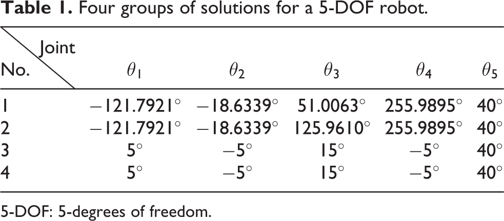
5-DOF: 5-degrees of freedom.
Because the third and fourth group of angles listed in Table 1 are equivalent to the ground truth, the simulated experiment verifies the correctness of the proposed method.
Actual experiment
For the practical test, we choose the 6-DOF Motoman-SV3X robot, YASKAWA company, as the testing platform, fix the wrist joints, and only allow movement of the waist, shoulder, and elbow joint, as shown in Figure 4; the end posture can be determined according to equation (27).


Experiment using the Motoman-SV3X.
Then, the three joint angles can be easily calculated via equations (24) and (25), where i = 1, j = 2, 3, and
To confirm the effectiveness of the proposed method, we sample 40 points along the circle and then track these points by respectively utilizing the proposed method and a radial basis function neural network (RBFNN). The result is shown in Figure 5, where the black points represent the sampling points, the red points, and the blue points represent the tracking points obtained via our method and the RBFNN approach, respectively. The one defining the mean distance errors between the red and black points is e1 and the one between the blue and black points is e2, as shown in Figure 6, the mean of e 1 and e 2 are 0.4794 mm and 1.9181 mm, respectively. Moreover, the respective computational speeds of the two methods are 2.31 and 12.681 µs. Comparing the results obtained via our proposed method with those obtained via the RBFNN approach, an approximate fivefold increase in accuracy and five times increase in the computational speed relative to our method is observed.
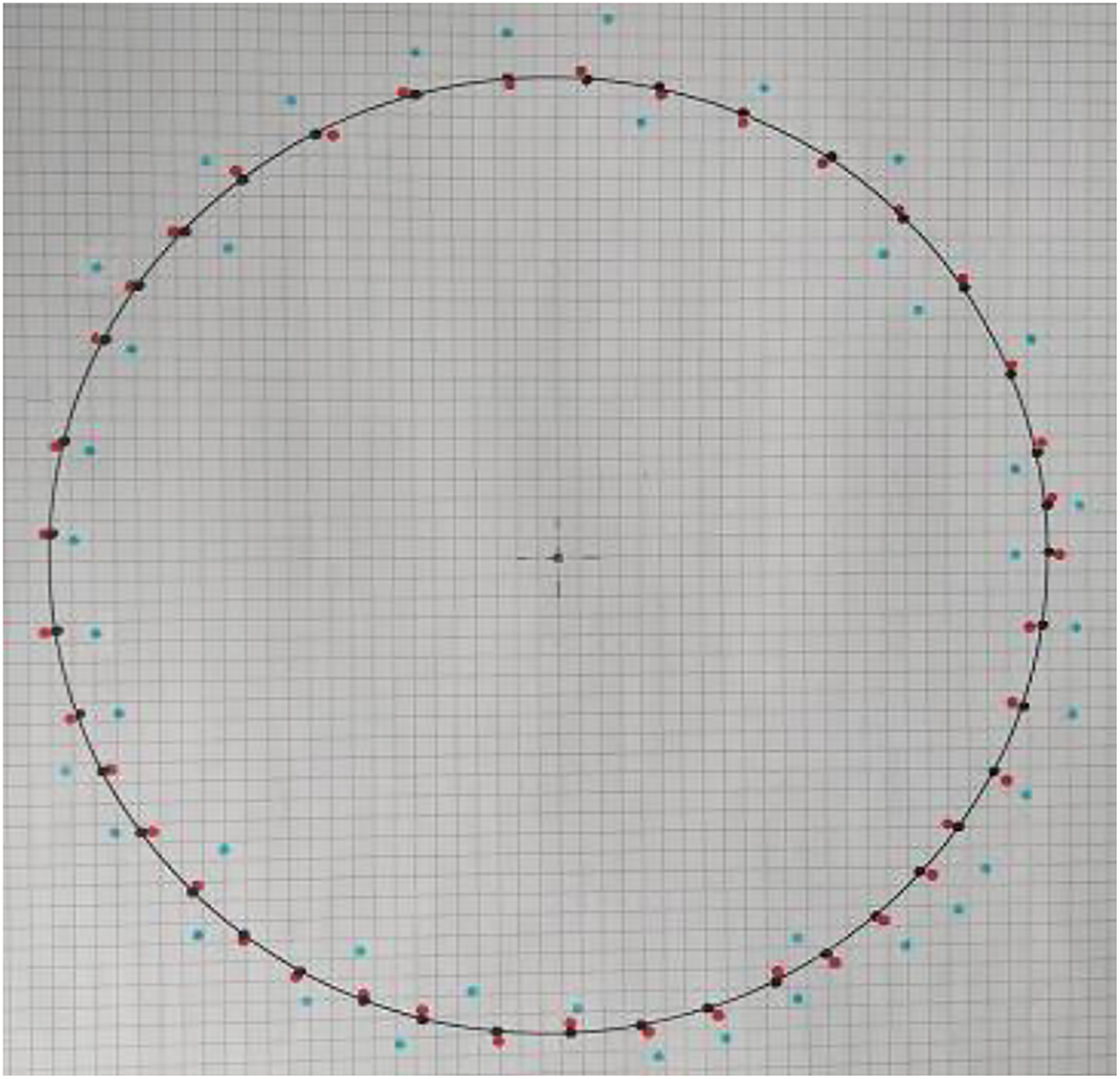
Tracking results.

Comparative results of the two methods.
Conclusions
In this article, a novel second subproblem, which is suited to the problems with two arbitrary axes, has been proposed. On this basis, a general and simple closed-form solution for 5-DOF robots is also provided. In general, the proposed method utilizes a few features of the screw theory and Rodrigues’ rotation formula to reduce the complexity of IK problems. Applying this methodology, three main advantages were determined, with the first advantage being that it can broaden the range of applicability of Paden–Kahan subproblems and can be applied to arbitrary 5-DOF robots satisfying the Pieper criterion, which has been demonstrated by adapting the methodology of an arbitrary 5-DOF robot. The second advantage is that it can simplify the problem-solving process for inverse kinematics, yielding only two formulas that can express the inverse solutions, thereby making the application of robot more convenient. Lastly, the methodology is stable and real-time owing to the adopted algebraic geometry algorithm, which takes into account the geometric relationships to build the constraint equation, and then solves the equation by employing algebraic approaches. Furthermore, the correctness and the validity of our method has been verified via actual and simulated experiments, with the results showing that our method offers considerably higher accuracy and reduced computational speed as compared to the RBFNN method. However, although the proposed method yields clear advantages, a standard explaining how to satisfy the Pieper criterion or how to extend our method to be applicable to 6-DOF robots has not yet been determined. Therefore, a general solution for 6-DOF robots will be researched in future work.
Footnotes
Acknowledgement
We are grateful to the reviewers for their valuable comments and suggestions which lead to improved presentation of this article.
Declaration of conflicting interests
The author(s) declared no potential conflicts of interest with respect to the research, authorship, and/or publication of this article.
Funding
The author(s) disclosed receipt of the following financial support for the research, authorship, and/or publication of this article: This work was supported by the National Natural Science Foundation of China (61503224, 61273197, 61773245, 61473177, 61603068), China Postdoctoral Science Foundation (2015M582115 and 2016T90640), SDUST Public visiting scholar, and Taishan Scholarship Construction Engineering.