
Abstract
Clustering plays an important role in processing light detection and ranging points in the autonomous perception tasks of robots. Clustering usually occurs near the start of processing three-dimensional point clouds obtained from light detection and ranging for detection and classification. Therefore, errors caused by clustering will directly affect the detection and classification accuracy. In this article, a clustering method is presented that combines density-based spatial clustering of application with noise and two-dimensional range image composed by scan lines of light detection and ranging based on the order of generation time. The results show that the proposed method achieves state-of-the-art performance in aspect of time efficiency and clustering accuracy. A ground extraction method based on scan line is also presented in this article, which has strong ability to separate ground points and non-ground points.
Introduction
Recently, the application of light detection and ranging (LiDAR) has become more widespread in autonomous navigation systems 1 –7 and three-dimensional (3D) environment reconstruction systems. 8 –12 In both areas, clustering as a preprocessing step of 3D point clouds is very important because it directly affects the accuracy of object classification and dynamic object detection. In autonomous navigation systems, the vehicle must detect objects on the street, such as pedestrians, moving vehicles, and other obstacles, to avoid accidents. Clustering can result in errors in object classification and dynamic object detection since object classification is usually executed after clustering according to the features of each cluster in order to recognize the category types to which they belong. There are some features of points perceived from LiDAR making, achieving a high clustering accuracy and online work difficult. Points generated by LiDAR are spatially distributed. The density and shapes of objects also vary significantly according to different sensors and objects. Most LiDARs generate a huge amount of points each second, which makes online work for navigation system a challenging work. After a long period of exploration, many algorithms have been proposed. The main purpose of those algorithms is to improve the clustering accuracy and execution speed.
Many clustering algorithms 13,14 proposed for processing image can be used for processing 3D LiDAR points since the principle of clustering is similar that they all aim at grouping points with similar features of a given data set. Since pixels belonging to one object in an image have close indices, the feature of image accelerates the speed to find similar elements. But for points, they are spatially distributed, accessing all the points in the data set is necessary to find the similar points if no measurements are taken. It takes too much time when the data set is large. Therefore, constructing a similar image for 3D LiDAR points is a wise choice to improve the algorithm efficiency.
Density-based spatial clustering of application with noise (DBSCAN) 14,15 is a clustering algorithm based on the difference of density. It is also well known for its ability to reject noise points based on a minimum number of points within a predesignated radius from a given point. Since the 3D LiDAR point clouds are often noisy, 16 DBSCAN can be the preferred algorithm to cluster 3D LiDAR point clouds. Nevertheless, it seeks every point in the given data set to find the nearest points and then clusters them together. It is thus time-consuming and is not suitable for online work when the data set is large. For improving its speed, usually special data structures 17 are necessary, such as constructing a kd-tree. Kd-tree-based DBSCAN can significantly enhance the searching efficiency 18 ; however, construction of a kd-tree is quite complex and also time-intensive.
In this article, a range image-based DBSCAN clustering method is proposed. It employs a two-dimensional (2D) range image in which each pixel stores the information of the corresponding point. University of Michigan North Campus Long-Term Vision and LiDAR Dataset (NCLT data set) 8 utilizing Velodyne HDL-32E is used. The speed of the proposed algorithm is compared with DBSCAN and kd-tree-based DBSCAN, which shows a significant improvement for 572.4 times faster than DBSCAN and 16.89 times faster than kd-tree-based DBSCAN. The clustering accuracy is 10.2% higher than Fast Segmentation algorithm 1 and 5.08% higher than Scan Line Run algorithm. 19
The remainder of this article is organized as follows. The “Related work” section introduces existing works relating to the research topic. In the “Range image-based segmentation” section, the proposed methods are described in detail. The “Experiments” section presents the results and analysis of conducted experiments. The “Conclusions” section concludes this article.
Related work
Clustering is an essential step in pre-processing LiDAR points. Hence, many studies have been conducted relating to it. 14,20 In this section, some existing studies are noted and are primarily grouped into two types.
The first type is based on voxel occupancy. It first partitions the points into voxels to form a higher level representation of points to achieve time reduction when the points must again be processed. 2,21,22 Aijazi 22 used a chain method to segment points after voxelization of points to reduce the clustering time. However, that method employed color information in aid of clustering. Himmelsbach et al. 2 applied point clustering on the non-ground voxels using a threshold in the vertical direction between voxels. Voxelization of points can significantly reduce the time by reducing the number of primitives that must be processed. However, this approach is prone to under-clustering of points.
The second type involves processing a point cloud based on single point. Since this kind of method relies on the structure of points, a preprocessing step to construct a specified point structure 11,13,23,24 is usually executed first. Otherwise, the consumption of time is unacceptable due to the iterative traversal of all the points in the given data set. Meanwhile, Shrihari et al. 11 and Klaas et al. 23 first constructed a kd-tree before clustering, which reduced the lookup time when searching the nearest neighboring points. In addition, Lu et al. 13 proposed a pairwise linkage structure to connect the given point with its closest point, which reduced the search time combined with a cutoff distance to cluster the points according to its local densities. All the mentioned data structures are quite complex and account for a large proportion of running time.
Range image 24 is also one kind of data structure that it organizes points in a way like image does. Each pixel of the image stores the position of one point. Points of LiDAR are usually generated in one scan line by one scan line, and if we take one scan line as one column or one row of the image, when the vehicle moves or the sensor rotates, the range image can be formed when we arrange the scan lines by their generated time. Our proposed method uses this approach. Unlike other structure mentioned above, which must traverse each point to form the indicated structure, the range image can be formed when the points are received from LiDAR. This is because the range image is related to the sensor 1 and the sensor information can be easily obtained. In this case, the construction of the range image does not require additional time because it is directly formed when the points are obtained.
In most clustering applications, clustering is typically performed only on non-ground points generated by applying ground extraction algorithms. 19,25,26 In this article, we proposed one new ground extraction algorithm based on scan line of the LiDAR. Since the range image consists of scan lines, so ground extraction algorithm can be applied based on the range image directly. This procedure requires only approximately 3.7 ms in the central processing unit (CPU) and 0.8 ms in the graphics processing unit (GPU). The algorithm needs two parameters as thresholds to constrain the maximum height difference and angle difference between two neighboring ground points in the scan line.
In this article, the proposed ground extraction is compared with the Ground Plane Fitting algorithm. 19 Our ground extraction algorithm shows better efficiency and achieves comparable performance. The proposed clustering method is compared with DBSCAN and kd-tree-based DBSCAN in aspect of speed. The results prove that our method achieves significant improvement in efficiency. It is 572.4 and 16.89 times faster than DBSCAN and kd-tree-based DBSCAN, respectively. The performance is compared with Fast Segmentation 1 and Scan Line Run algorithms. 19 Our method achieves 84.82% clustering accuracy. Fast Segmentation and Scan Line Run algorithms achieve 74.42% and 79.74% clustering accuracy, respectively. Our method shows state-of-the-art performance in both clustering accuracy and time consumption, which can be run in real time.
Range image-based segmentation
The abovementioned clustering methods are detailed in this section. Figure 1 illustrates the processing flow of the proposed method, which is mainly composed of three parts: 2D range image construction, ground extraction, and non-ground object clustering processes.

Processing flow.
2D range image construction process
A 2D range image is constructed based on scan line. It can be used for 2D LiDAR as well as 3D LiDAR. For a 2D LiDAR mounted on the top of a car as shown in Figure 2, the height of the range image is the number of the points in one scan line, and the width is the number of scan lines. In the range image, each pixel stores the information of a point. The neighboring points in one column of the image are generated by adjacent lasers and the neighboring points in one row image are generated by the same laser in consecutive scan lines. The neighboring points in the range image are inclined to form the same object. This can enhance the efficiency when searching neighboring points is required.

Range image generated by 2D laser scanner. 2D: two-dimensional.
Ground extraction process
Like most clustering methods, the ground is first removed by ground extraction method. In this article, the ground points are extracted based on scan lines by considering the maximum height δ and maximum angle β between two neighboring ground points in one scan line.
Given a frame of points

Ground extraction.
Suppose the beginning point, p i0, which is closest to LiDAR in this scan line, is the ground point (Algorithm 1, line 1). Then, its neighboring points p i1 along the scan line is found, as depicted in Figure 3. As the 3D coordinates of p i0 and p i1 are already known, their height difference h 1 and angle difference θ 1 can be easily calculated (Algorithm 1, lines 9–10). Given that h 1 and θ 1 are both greater than the thresholds, the point p i1 is not one of the ground points. Thus, the next point p i2 should be compared with p i0 because p i0 is the closest known ground point to p i2 in the scan line.

Principle of ground extraction.
As shown in Figure 3, h 2 and θ 2 between p i0 and p i2 are smaller than the thresholds β and δ. Therefore, p i2 is one of the ground points (Algorithm 1, lines 11–13). The above steps are repeated (Algorithm 1, lines 2–17) until all the points in the scan line are classified into ground points and non-ground points. In this algorithm, the two thresholds affect the result of ground extraction, which should be decided according to the maximal size of ground obstacle that can be neglected. For big thresholds, some small blocks lying on the ground will be classified as parts of ground.
Non-ground object clustering process
In this section, implementation details of range image-based DBSCAN are described. Like traditional DBSCAN algorithm, a distance constraint condition ep and the minimum number of points, minPts, for a qualified point are defined. In addition, a k is defined to indicate how many neighboring pixels will be searched, as shown in Figure 4. Figure 4 (left) is observed along the direction of laser flying, which shows similar view in a range image. The k is the number of positions in the red box, which represents the searching range. From Figure 4 (right), points in the red box are from a tree and a car. The current point O is located in the centroid of the red box, which belongs to the tree. For the distance constraint condition, the points from the car are too far from O, so they are not qualified points. Only the points in the green box are successfully classified as same cluster with O if the number of points in green box is not less than minPts.

Points of one frame in 2D view (left) and 3D view (right). 2D: two-dimensional; 3D, three-dimensional.
Algorithm 2 details the enhanced DBSCAN algorithm, where P denotes the points of one frame, and Label is an array denoting the label of each point in P. The points in P are stored according to their position in the range image.

Range image-based DBSCAN.
The points in one frame are traversed vertically (Algorithm 2, line 4) and then horizontally (Algorithm 2, line 3). When a point is not labeled, by using the range image, the points in its k neighboring positions can be found and then separated into qualified points and unqualified points very quickly (Algorithm 2, line 5). To this end, the distances between the neighbors and current point (Algorithm 2, line 12) are compared with the defined threshold ep. In this step, a point set of seeds that stores the positions of the qualified neighbor points is obtained. If the number of points in the seeds is smaller than minPts, then the current points can be regarded as noise and it should be denoted as noise point (Algorithm 2, lines 13–14). Otherwise, a valid label is assigned to all points in the seeds and the current points (Algorithm 2, lines 15–20). For every points in seeds, their k neighboring positions are also searched (Algorithm 2, line 21); if the number of neighboring points within ep from a given point in seeds is greater than minPts, those points will also be labeled with the same label (Algorithm 2, lines 26–37). For the points are labeled UNCLASSFIED, it will be added to the seeds (Algorithm 2, lines 31–33).
Experiments
The performance of the proposed method was verified by experiments performed on a desktop computer with an i7-6700 CPU 3.4GHz CPU produced by Intel and an GeForce GTX 1060 graphics card produced by NVIDIA. The NCLT data set collected by Velodyne 32 was used. The experiments consist of four parts: 2D range image construction, ground extraction, time elevation, and performance elevation. For ground extraction, the Ground Plane Fitting algorithm was used to compare our proposed ground extraction method. For time elevation, the DBSCAN and kd-tree-based DBSCAN were used to compare the time consumption. Fast Segmentation and Scan Line Run are used to compare the performance of clustering result to our method. Experiments prove that our ground extraction method is efficient and has comparable ground extraction result to the Ground Plane Fitting method. Our non-ground object clustering method can work online and shows good clustering accuracy with 84.82%, which is 10.4% higher than Fast Segmentation and 5.06% higher than Scan Line Run algorithm.
2D range image construction
The LiDAR has 32 lasers established in a vertical direction to form a specific direction, and 3D points were generated by rotating the LiDAR head in 360 degrees. The range image was constructed based on the LiDAR feature into a cylindrical or rectangle shape after being unfolded. The points produced from 32 lasers were arrayed in one scan line, and they were represented as one column of pixels in the range image. The width of the range image represents the number of scan lines that could form one frame. Thus, the range image constructed relations of all the points, whereby the neighboring points were generated by adjacent lasers in a vertical direction, or by the same lasers in adjacent scan lines. Figure 5(a) shows one range image corresponding to the segmented result in Figure 5(b). This approach enabled enhancement of the searching speed because the neighboring points had a greater possibility of being from the same object.

points of one frame in 3D scene and range image. (a) Range image; (b) points in 3D scene. 3D: three-dimensional.
Ground extraction
In this section, Ground Plane Fitting algorithm was implemented to compare with proposed ground extraction method, as shown in Figure 6. The original scene is shown in Figure 8(a). In Figure 6, the ground points were successfully separated from non-ground object points in two ground extraction algorithms. But our method has better performance in speed, which is shown in Figure 7. Ground Plane Fitting algorithm took 9.8 ms on average. Our method in CPU and GPU, by comparison, only took 3.7 and 0.8 ms, respectively.

Ground extraction results.

Ground extraction time consumption.

Ground extraction with different thresholds. (a) Original point clouds; (b) results with δ = 0.45 m, β =
The ground extraction result is controlled by δ and β. As shown in Figure 8, with increase in δ, points belonging to non-ground objects were classified as ground points as shown in the red box and circle (Figure 8(c)). With decrease in δ, points belonging to ground were failed to be classified as ground points as shown in red boxes (Figure 8(d)). In Figure 8(b), the ground was well extracted. Changing β will have similar effect.
Time evaluation
To prove the improvement in aspect of efficiency, DBSCAN 14 and kd-tree-based DBSCAN 18 were compared with the proposed method. Figure 9 shows the time required by each algorithm. The figure shows that DBSCAN was time-consuming because it required 26,411.6 ms on average, while kd-tree-based DBSCAN required 779.142 ms on average. In contrast, the range image-based DBSCAN required only 46.14 ms on average, and can be run in real time. It is much faster than DBSCAN and kd-tree-based DBSCAN.

Time consumption comparison.
Performance evaluation
Fast Segmentation and Scan Line Run are used to compare the proposed method in aspect of clustering accuracy. One threshold is for clustering the points in one scan line, which was set to 0.6 in experiment, and another is for merging clusters between two scan lines, which was set to 1.4. Fast Segmentation utilizes angle difference between two objects. Therefore, Fast Segmentation needs only one angle threshold, which was set to 0.5 degrees. For our method, thresholds were set to k by 16, minPts by 2, and ep by 0.9. The results are shown in Figure 10. The cars close to the sensor were clustered as one cluster from the figure generated by Scan Line Run and Fast Segmentation. The cars, by comparison, were well clustered by our method. Scan Line Run needs two threshold for clustering.
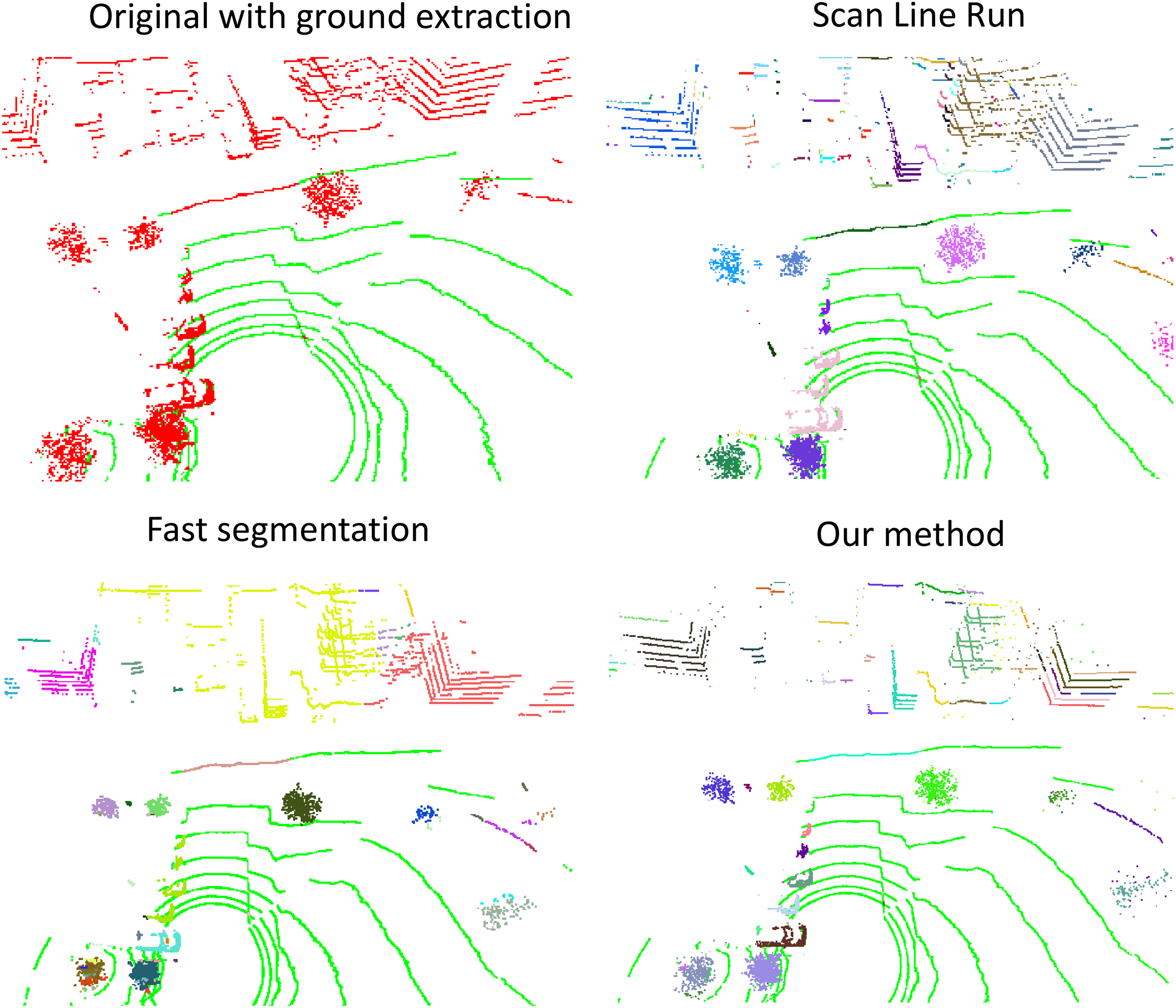
Object clustering results.
The proposed method inherits the feature of DBSCAN that it is sensitive to density. As shown in Figure 11, when change ep with k and minPts unchanged, the required intensity was changed. In Figure 11(a), the ep was set to 0.9 m, points far from sensor inclined to be over-clustered. If the ep was increased to 1.3 m, points close to the sensor inclined to be under-clustered, as shown in Figure 11(b). The current approach is to give priority to the close points since the close objects are more important for autonomous ground vehicles.
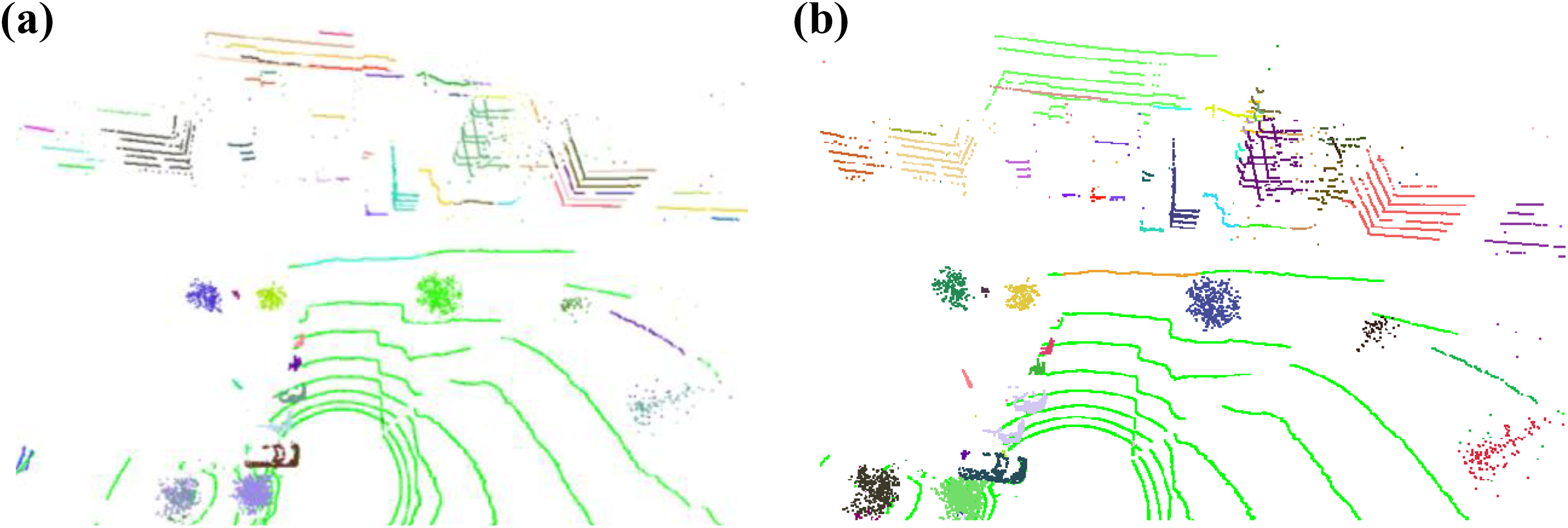
Results with different threshold. (a) ep = 0.9 m; (b) ep = 1.3 m.
To calculate the precision rate, 408 objects in 10 frames were manually segmented as ground truth data by software designed by the present authors. The precision was calculated based on the process of continually trying the new parameters of these two algorithms. Finally, Fast Segmentation achieved a maximum precision of 74.42% and Scan Line Run achieved a maximum precision of 79.74%. The proposed method, by comparison, achieved a maximum precision of 84.82%. The proposed ground extraction method and non-ground object clustering method are both efficient and can produce state-of-the-art performances for ground vehicle navigation.
Conclusions
In this article, a ground extraction method using scan line and a clustering method based on range image combining DBSCAN were proposed for clustering of 3D points. Ground Plane Fitting method was used to compare the ground extraction result, which showed that our ground extraction method was more efficient. DBSCAN and kd-tree-based DBSCAN were used to compare to our object clustering method to prove the improvement of speed. The results showed that our method achieves 572.4 times faster than DBSCAN and 16.9 times faster than kd-tree-based DBSCAN on average. To prove that our object clustering method has good clustering performance, it was compared to Fast Segmentation and Scan Line Run. The results showed that our method achieved 10.2% higher accuracy than Fast Segmentation and 5.08% higher accuracy than Scan Line Run.
Our object clustering method still has deficiency. It cannot give consideration to both close points and far points for that the intensity is fixed but the densities are different for close points and far points. Our future work is trying to use different density based on the distance of points from sensor. This can be configured by increasing ep with respect to the distance of the point.
Footnotes
Declaration of conflicting interests
The author(s) declared no potential conflicts of interest with respect to the research, authorship, and/or publication of this article.
Funding
The author(s) disclosed receipt of the following financial support for the research, authorship, and/or publication of this article: This work was supported by the National Research Foundation of Korea (NRF) grant funded by the Korea government (MSIP; NRF-2015R1A2A2A01003779).