
Abstract
In this article, we survey the recent developments of sensing methods in three-dimensional robot vision, centering on the current three-dimensional sensors and core techniques embedded in robotic systems. Over 8000 publications have reported rather wide application areas of three-dimensional robot vision in the last 40 years, such as human–robot interaction, object recognition, three-dimensional modeling, object tracking, searching and surveillance, as well as robot manipulation, localization, navigation, mapping, and path planning. Representative works and future research trends are also addressed in this article.
Introduction
In the 1970s, with the development of modern control theory and sensor technology, robots started the real production process. A robot equipped with a camera based on a CCD ship formed the earliest robot vision system. In the 1980s, vision sensors entered a period of rapid development. Robots equipped with electronic camera, range finder, and such sensors established an advanced visual system to help the robots to perform independent reasoning and motion planning in unstructured environments. The visual system 1 is recognized as the core entrance for robots to be intelligent. In the 21st century, robots equipped with advanced image acquisition system and stereo vision technology have appeared, leading to the importance of three-dimensional (3D) vision system on the mobile robots being widely recognized.
The development of 3D robot vision is actually based on the improvement of vision algorithms and 3D sensors. 2 Through decades of innovation, vision algorithms in the robot vision system have formed three classes: human–robot interaction, 3 –13 identification and perception, 14 –20 and movement decision. 21 –34 Corresponding to these classes, the main applications contain gesture recognition, 3,5,9,11,12,35 target tracking, 10,36 –39 human eye tracking, 13,40 map building, 20,25,41 –44 scene understanding, 33,34 object recognition, 16 –19,45,46 location and pose recognition, 21 –23 autonomous navigation, 20,24 –28 and path planning. 29 –32
It is inseparable between the development of 3D robot vision and the evolution of optical sensors. We divide the visual sensors equipped in the robot vision system into three categories: one-dimensional linear array transducer represented by single laser radar, 47 two-dimensional array of sensors represented by the embedded camera, 48 and 3D depth sensors represented by special light source camera. 49 The 3D depth sensor is the main and most critical sensor for robots to realize the 3D vision system. The quality of 3D data acquisition directly influences the outcome of the backend algorithm for the mobile robot and the control of decisions.
The current mainstream techniques of a 3D depth sensor in robot vision are generally developed after 2010. The technology routes are as following: monocular structured light technology based route, 50 binocular structured light technology based route, 51 and time of flight (TOF) technology based route. 52 The principle of structured light is using the optical diffraction principle of laser, and the sensor projects particular patterns to accelerate or assist acquiring depth information. Four particular patterns included are regular pattern, pseudorandom, random dot speckle, and special graphics pattern. The advantage of structured light is the high accuracy and fast refresh rate, but the drawback is its unsuitability for the outdoor environment under bright light. TOF technique is using the phase delay of the modulated light source received at different distance and calculating the depth according to the speed of light. The advantage of this principle is the maintenance of measurement accuracy with increasing distance, but the disadvantage is the low resolution and instability to the environment disturbance.
This article briefly reviews the state of the art concerning vision algorithms and 3D sensing devices applied in 3D robot vision, and presents their applications in different fields. The “Overview of contributions” section provides a brief overview of related contributions in 3D robot vision. Representative vision techniques and applications are surveyed in the “Vision processing in robotic systems” section. The “3D sensing methods” section lists the relevant 3D sensing techniques and the most important recent developments in robotics sensors. The “Future trends” section is a discussion on current and future trends. The conclusion is drawn in the “Conclusion” section.
Overview of contributions
Summary
There are about 8000 research papers closely related to 3D robot vision published from 1976 to 2017, as shown in Figure 1. Yearly distribution shows this topic emerged around the year 1976 and rapidly developed within the past 10 years.

Yearly published records on 3D robot vision in the last 40 years. 3D: three-dimensional.
Representatives
A 3D vision robotic system finds its place in many fields from industry and robotic services. Their most significant applications are summarized in the following list:
Robot vision has made considerable development, and complexity and cost are sustained reducing. With the introduction of 3D technology, 3D robot vision has rapidly penetrated into many new application areas, not only in all industries but also in medical treatment, entertainment, and services.
Industrial detection
Currently, robotic vision has successfully applied in industrial testing detection, such as product packaging and printing quality detection, 68 beverage container inspection, 69 beverage filling quality detecting and beverage products sealing detection, 69 timber wood inspection, 70 the semiconductor integrated packaging quality inspection, 71 and steel coil quality inspection and grading of fruits detection, 72 , which not only greatly improves the quality of the products and reliability but also ensures the production speed. In the pharmaceutical production line, robotic vision technology can be used for drug packaging detection and medicine loading inspection. 73
Medical science
In the field of medical science, while vision processing is inevitably used in some surgical robots, it is also used to assist doctors in medical image analysis, mainly using digital image processing technology and information fusion technology to analyze the nuclear magnetic resonance (NMR) images, computed tomography images, and other medical imaging data. 74 Different medical imaging devices can obtain biological tissue images with different characteristics. For example, X-ray images reflect the bone tissue, while NMR images reflect the organic organization. Doctors need to consider the mutual impact of bone and organic organization. Thus, the two kinds of images need to be fused using digital image processing techniques for medical analysis. 75,76
Robot navigation and visual servo
Robot vision is a most important part in robotics, whose purpose is giving feedback to the robot motion control system about the location of the target or the pose and location of robot itself through vision techniques such as 3D location, scene understanding, and so on. Visual servo system is used for robot manipulator, 77 localization of humanoid robot for locomotion tasks, 78 object recognition with pose estimation, 79,80 robot ego-motion estimation, 81,82 and object grasping. 83,84
Aeronautics and astronautics
Satellite remote sensing image information is usually very huge. In addition, there are many interference and error data, so it is difficult to process and analyze this kind of data. The 3D robot vision technology is used to analyze all kinds of remote sensing images for environmental monitoring, geography measurement, and 3D reconstruction. 85 According to the 3D characteristics of topography landform images, automatic recognition, 24 understanding and classification can be done. Moreover, 3D robotic vision can be applied to the movement and planning of unmanned aerial vehicle (UAV), such as position and orientation measurement for autonomous aerial refueling 86 and UAV visual path planning. 87
Vision processing in robotic systems
Target representation
The goal of robotic vision is to make the robots identify objects, like people, not only to capture the object but also to understand the representation of the objects. Representation is a main step in object recognition. For robots, different object representations (mainly refer to different mathematical models) can determine the ability and reliability of object recognition directly. The observations of an object in different views correspond to different images, and sometimes the difference between the images is very large. It is hoped that the representations of an object have as weak relationship as possible to the observation angle of the object. Currently, it is difficult for robots to handle the recognition problem of an object under different observation angles. However, it is not very sensitive to human under this kind of changing observation angle in object recognition. Therefore, the study of human visual representation is an effective way to solve the object visual representation problem for robots.
There are many literatures giving out a lot of mathematical descriptions for object in different ways, such as feature description, invariant descriptions, and elastic model. However, all these models are only some representations of some special objects in the special environment, and they are less than the general object representation level. According to the current literatures, there are two main models for object representation. The first is a view-based two-dimensional (2D) image model and the second is a 3D shape model.
Biologically, target recognition might be based on both the 2D image model and 3D shape model. When people perform object recognition, although the time difference between recognition from the front image of the object and recognition from the side image of the object is very small, the difference still exists. That means the object representation in the human vision system is not exactly a 3D representation. If it is a 3D representation, the time of object recognition from the front image and the side image should be exactly the same. Some representation forms are proposed based on images. 88 –90 In this kind of representation forms, the representation of object in human vision is not the 3D geometry shape, but a set of images of the object in different views. Under this model, the process of object recognition becomes the matching process between the input images and the stored images of the object. This mathematical model is based on the so-called subspace method. That is to say, although in theory it can be projected into innumerable different images for one object, but in the case of allowing a certain small error, any image can be linear combined with a limited number of base images. The brain only needs to store the images. However, this is unreasonable, since there are a lot of depth information sensitive neurons in our brain. If the depth information obtained by neurons is useless for object recognition, these cells should be already degraded in the process of human evolution. Thus, the image-based representation model is not very mature.
The 3D shape model is proposed by David Marr in the 1980s. 91 The basic idea is: the representation of an object in our brain is the 3D geometry shape. Because the 3D shape of the object has nothing to do with the angle of view, the representation of the object in the human vision system has nothing to do with the angle of view. Marr’s 3D representation model is the origin of computer vision and it still has an important influence today. In Marr’s paper, the 3D shape model is also known as 3D reconstruction theory. Marr’s theory holds that people first extract some simple primitives from the 2D image such as dot, line, and area, then recover the depth of these simple primitives using visual module such as binocular stereovision and motion vision, and at last, give a simple representation of the whole shape of the object. However, Marr’s 3D model meets a lot of difficulties in practical applications. 92 The main difficulty with the Marr’s 3D representation model is that the computer can’t reliably recover the lost 3D depth information from 2D images during image processing. Then, theories like hierarchical reconstruction were proposed to overcome the robustness problem in the depth recover process. 93,94
3D representation
According to the object description coordinate system, the 3D object representation methods can be divided into two categories: object centered and viewer centered. The object-centered representation methods focus on the coordinate system of object and use the features of the object itself such as the corners, holes, and edges which have nothing to do with the point of view. However, the viewer-centered representation methods make certain that the appearance of the object depends on one or more points of views to observe the object and use viewpoint-related features such as the edge of the occlusion, outline, and shape of the T-connection to do so.
According to different sizes of geometric features used for object representation, representation methods can be divided into the following six classes 1 : representation methods based on 3D points, mainly using the information of the depth data, the normal directions of the points on the surface, and the curvature 2 ; representation methods based on the convex point, mainly using the vertexes, the corner points and the points with maximum and minimum curvature of the object 3 ; representation methods based on the shape, mainly using the edge information of the object 4 ; representation methods based on the surface, mainly using the surface information of the object, such as plane, spherical surface, quadric surface, and the connected relation between the surfaces 5 ; representation methods based on the body, mainly using the body descriptor of voxel, ellipsoid, superellipsoid, and so on 6 ; and representation methods based on the parts, mainly using the basic components of the object. A few kinds of 3D object representation methods based on the feature selection are as follows.
Basic surface feature
Early contributions use some basic features on the surface of the object, such as Grimson and Lozano-Perez 95 used edge, straight-line segment, and the normal vector to represent the polyhedron. Since using polyhedron representation to approximate the curved surface of the object needs a lot of space, quadric equation has been proposed to represent the curved surface of the object. 96 There are also some representation methods based on the Gaussian curvature and mean curvature of the surface points. 97 Meanwhile, a structure representation method has been proposed in the study by Stein and Medioni 98 and this method determines the edge and the local surface based on the distribution of the normal vector, so it can handle the arbitrary shape of the surface of the object. In general, representation methods based on the local boundary and the basic surface features are sensitive to the noise in the data, and the accuracy depends on the reliability of the feature extraction from the input images.
Discontinuity
Some representation methods use the discontinuity of the surface of the object; for example, the method of Godin and Levine 99 applied the ridge and the crease edges of the object to construct the edge-junction graph, and then represented the object by using the edge-junction graph. However, Chen and Stockman 100 comprehensively used the surface and breakpoint information to mark the edges, the authors also used 2D contour features to describe arbitrary-shaped 3D objects. 101 Since the representation methods based on the discontinuity of the surface use the edge information of the object, the storage requirement is reduced. But, in most cases, the representation is incomplete because of the lost surface information.
Surface fitting
Global object representation methods fit the object surface using a parametric equation. Researchers analyzed the invariability of some parameters in higher-order algebraic equations and used these parameters to represent surfaces of 3D objects. 102 Other surface fitting methods such as B-spline are also used. 103 In addition, the superquadric surface feature was first introduced by Barr, where the authors fitted the data by an implicit equation. 104 In this type of methods, the object occlusion becomes a difficult problem, because the algebraic polynomial generated by the part surface of the object may be different from the algebraic polynomial generated by the whole surface of the object, and the algebraic equation parameters are obtained from region segmentation, so the accuracy of the parameters depends on the segmentation results.
Orientation
Each point on the object surface can find a corresponding point on the Gaussian ball which has the same surface direction. If the surface of the object is convex, the above correspondence is one-to-one correspondence. However, the disadvantage of the Gaussian ball is ambiguity, because it cannot save the transformation and size information of the object. Some improved methods projected the surface normal vector to unit ball according to the support function, such as the Generalized Gaussian Image, 105 which stored the connection information of adjacent points on the ball to ensure the unique presentation of the object. Representation methods based on orientation mainly describe the surface information of the object. Although these are global representation methods, they are too cumbersome and fail to handle the objects with occlusion. In addition, it is also very difficult to obtain segmentations of single objects from the whole scene Gaussian image.
Grid
Grid representation methods use polygons to represent the shape of the object, commonly using a quadrilateral and triangular grid. Due to the large amount of data, the storage, transmission, and calculation are very difficult. It is hard to be directly used in 3D object recognition. Thus, these representations need to be converted to other representations. In the study by Johnson and Hebert, 106 the authors transformed the geometric relation between the vertexes in the gird into a 2D image which is called spin-image, and they used the spin-image to describe the feature of 3D points in recognition. Despite the introduction of the simplified algorithm, the calculation used spin-image is still too complicated.
Voxel
Voxel representation methods are mainly used to describe the body feature of an object. 107 Similar to the pixel in the image, the voxel represents a small volume in the space, and it describes the object as a collection of nonoverlapping cubes. These voxels distribute in the 3D space to represent the object. The voxel representation methods are not suitable for object recognition, but are more suitable for surface reconstruction and modeling.
Octree
Octree representation methods describe the object hierarchically. Each node has eight branches in the tree structure and the root node is a cube which can completely cover the object. In hierarchical description, the space occupied by the object is divided into eight components step by step in the iteration, and the stop condition of the iteration is that each final cube becomes homogeneous in some features. The work of Chien et al. 108 proposed a method to generate the octree model of the object using three pairs of vertical depth images. Another octree generation method using the depth images in arbitrary angle has been proposed in the study by Li and Crebbin. 109 This method can describe the concave surface of the object. Octree representation methods can describe the global feature of the object, but they are not accurate representations, and the approximation of the representations depends on the accuracy of the segmentation.
Simultaneous localization and mapping
SLAM is the forefront technique of spatial location in robotic vision. 110 This technique is mainly used to solve the camera location problem in the space and create an environment map. The architecture of SLAM includes two main components: the front end and the back end. The front-end abstracts sensor data into models that are amenable for estimation, while the back end performs inference on the abstracted data produced by the front end. 111 This architecture is illustrated in Figure 2.

The standard architecture of SLAM. 111 SLAM: simultaneous localization and mapping.
A standard formulation of SLAM can be addressed as following. Assume that a robot is moving in the environment as shown in Figure 3, the trajectory of the robot X = {xk : k = 1, …, m}, the landmarks Y = {yN : N = 1, …, n } in the environment. When the robot moves from the moment k − 1 to k

where g(⋅) is the motion model, U = {uk : k = 1, …, m} is the input data of sensor, and σk is the random measurement noise. At the moment k, landmark yi is observed.


Visual SLAM process. 112 SLAM: simultaneous localization and mapping.
where h(⋅) is the observation model, zk,i is the observation at the observation point xk , and τk,i is another measurement noise. Equations (1) and (2) constitute the basic mathematical model of SLAM. This is a state estimation problem which can be solved by filter or nonlinear optimization.
SLAM is more like a concept than a single algorithm, as illustrated in Figure 2, the front end is a visual odometer to estimate the inter-frame motion of the camera and the position of the landmark. The back end is an optimization, according to the pose of the camera measured by the visual odometer at different moments, calculating the maximum posterior probability. The loop-back between the front end and the back end is a detection about whether the robot has reached the previous position. At last, a map of task’s requirement should be built according to the trajectory and the observations of the camera.
SLAM technology covers a wide range of applications and there are many kinds of classifications for SLAM according to different sensors, application fields, and core algorithms. According to the different sensors, SLAM can be divided into 2D and 3D SLAM based on laser radar, RGB-D SLAM based on the depth camera, visual SLAM based on vision sensors, and visual inertial odometry SLAM based on vision sensors and inertial unit.
The 2D SLAM based on laser radar is relatively mature. Thrun et al. 112 have determined the basic framework of the laser radar SLAM and the work of 2D SLAM has been concluded very thoroughly. The current grid mapping method has more than a 10-year history. Google open source of the laser radar SLAM cartographer can integrate the information of an inertial measurement unit (IMU) and uniformly deal with 2D and 3D SLAM. At present, 2D SLAM has been successfully applied in floor mopping robot.
RGB-D SLAM based on the depth camera is developing rapidly in the past few years. Since Kinect was introduced, several important algorithms successively appeared in just a few short years, such as Kinect fusion, 113 kintinuous, 114 voxel hashing, 115 and dynamic fusion. 116
Vision sensors include monocular camera, binocular camera, fish-eye camera, and so on. Due to the low price of visual sensors and can be used indoor and outdoor, visual SLAM becomes a research hot spot. The early visual SLAM such as mono-SLAM is more like a filter method extending from the field of robot. At present, the optimization methods in the field of computer vision are more frequently used, such as the bundle adjustment in structure from motion. In visual SLAM, the visual feature extraction method can be divided into direct method and feature method, the representative of the popular algorithms such as ORB-SLAM (a feature-based monocular SLAM system), 117 SVO (semi-direct monocular visual odometry), 118 and DSO (direct sparse odometry). 119
Vision sensors cannot work for non-texture areas. However, an IMU can measure the angular velocity and acceleration by the built-in gyroscope and accelerometer, and then calculate the pose of the camera. An IMU is quite complementary to vision sensors. Therefore, visual inertial odometry SLAM based on the fusion of measurement information from IMU and vision sensors becomes another research hot spot. According to the different information fusion methods, visual inertial odometry SLAM can be divided into two categories: method based on filtering and method based on optimization. The representative algorithms of visual inertial odometry SLAM are extended Kalman filter, 120,121 multi-state constraint Kalman filter, 122 preintegration, 123,124 and open keyframe-based visual inertial SLAM. 125
Overall, compared to SLAM based on laser radar and SLAM based on depth camera, visual SLAM based on vision sensors and visual inertial odometry SLAM is not mature enough. The operation is difficult, and needs to fuse with some other sensors and be used in a controlled environment.
Representative applications include virtual reality and augmented reality fields, which are to render the virtual objects in the environment according to the map information and the current perspective information from SLAM, and the sense of reality of the virtual objects can be greatly enhanced. In the field of UAV, 126 SLAM can be used for map building, 127 autonomous obstacle avoidance, 128 and path planning. 129,130 In the unmanned vehicle field, SLAM technology provides visual function of odometer for mixing with other location techniques. 131 In the field of robot location and navigation, 132,133 SLAM can be used for environment map building. 134 Based on this map, the robots can perform path planning, 135 autonomous searching, and navigation tasks. 136
3D sensing methods
3D sensing
Applications such as object recognition, 3D SLAM, and target tracking demand the vision systems of the robot to have the capability of generating 3D image data. Both passive and active techniques can be used to perform such tasks, each of which is listed in the following. 3D sensing techniques applied in robotic vision are shown in Table 1.
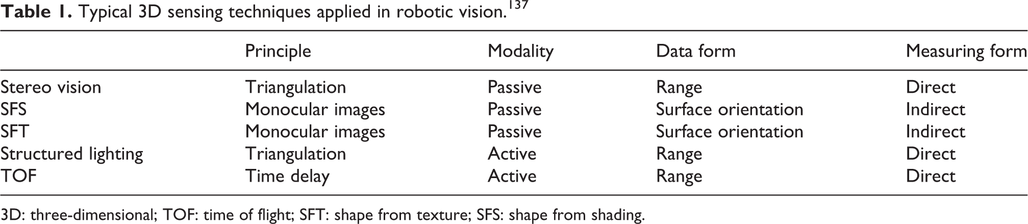
3D: three-dimensional; TOF: time of flight; SFT: shape from texture; SFS: shape from shading.
Stereo imaging
The stereo system uses two cameras to capture the images of the object from two different views. Like human eyes, the computer processes the different locations of the object point projected onto the two images to get the solid object. This method is similar to the human visual function. However, the calculation is relatively complicated. A typical stereo vision system is shown in Figure 4(a). For stereo cameras with parallel optical axes (Figure 4(b)), the 3D position of the point P can be derived from the following equations


where f is the focal length, b is the baseline, corresponding image points (xl, yl ) and (xr , yr ), and d is the disparity of the point.
This technique has been widely used in robotics, such as mobile robot navigation and mapping, 139 –141 robot hand-eye coordination, 142 human–robot interaction, 143 obstacle avoidance and path planning, 144,145 and mobile robot localization. 146
Shape from shading
Shape from shading (SFS) is also a common method. 147 Considering the shadow boundary of the image contains contour feature information, so it is able to take advantage of the illumination degree of the image under different conditions of light and shade to calculate the depth of the object surface, and then 3D reconstruction could be done based on the model of reflect light. It is important to note that the brightness of pixels is restricted by the light source, camera parameters, target surface materials, and so on.
The shadow recovery shape method has a wide range of applications, which can restore the 3D model of various objects except for the mirror. This technique is used for 3D reconstruction in human–robot interaction, 148 –150 and an example is shown in Figure 5. The disadvantages are that the process is too mathematical and the reconstruction results are not precise, and it cannot be ignored that the SFS method requires accurate light source parameters, including location and direction information. This causes it unable to be applied to complex light conditions such as outdoor scenes.

Shape from shading. 147 (a) A real face image. (b) Surface recovered from (a) by the generic SFS algorithm with the perspective model, with the light source located at the optical center. SFS: shape from shading.
Shape from texture
The surfaces of different objects have various texture information. This information is composed of texture elements, which can determine the surface direction and then restore the corresponding 3D surface. This method is called shape from texture (SFT). 151 In theory, the texture as the repeated visual element in the visual field covers the object surface in various positions and directions. When an object with a texture element is projected onto the plane, its corresponding texture element will bend and change. For example, perspective contraction deformation makes the texture longer because the smaller includes angle between the plane and the texture. The projection deformation will make the texture element larger which is closer to the plane. According to the measurement of the image, the deformation can be obtained and then the depth can be calculated based on the distorted texture element. SFT requires strict requirements of texture information on the object surface. It is necessary to understand the distortion information of the texture element in the imaging projection.
Structured lighting
The structured lighting method, by transmitting special light to the object surface, obtains the depth information based on the stereo information in the light source. 152 The specific process consists of two steps, first using the laser projector to project the encoded beam onto the target object to generate the feature points. Then, according to the projection model and the geometric pattern of the projected light, calculating the distance between the feature points and the camera optical center using the triangulation principle, which can generate the depth of the feature point and implement model reconstruction.
The encoded beam is the structure light, including various patterns such as points, lines, faces, and so on. The structure lighting method solves the problem where the object surfaces are flat, single texture, and slow gray change. Because of the easy implementation and high precision, the structured lighting method has a very wide range of applications. There are several hardware equipment produced based on the structured lighting technology, such as the Prime Sensor from PrimeSense, Kinect from Microsoft device and Xtion PRO LIVE from Asus.
The basic application of the structured light technique in 3D robot vision is also for depth perception. 153,154 For the mobile robots, structured lighting has been used in navigation and obstacle detection, 155,156 scene understanding, 157 and 3D reconstruction. 158,159 Other applications include shape acquisition, 160 object modeling, 161 3D hand-eye robot vision system, 162 high-speed 3D structured light imaging techniques, and potential applications to intelligent robotics. 163
Figure 6 shows the basic principle of structure light 3D measurement. The camera is usually described as a perspective projection model 164 and the corresponding relations between the object space and the image plane can be expressed as follows


The basic principle of 3D measurement by structure light. 137 3D: three-dimensional.
where (uc , vc , 1) and (Xw , Yw , Zw , 1) are the homogeneous coordinates of a point P in the camera image coordinate system and the object world coordinate system, respectively; s is an arbitrary scale factor; and Mc is the linear transformation matrix of 3 × 4. The projector can be regarded as an inverse camera. Therefore, it has a similar model as equation (6)

where (up , vp , 1) is the coordinate of a point P in the projector image coordinate system, s* is an arbitrary scale factor, and Mp is the linear transformation matrix of 3 × 4. Thus, the 3D coordinates (Xw , Yw , Zw , 1) of measured points can be obtained by equations (6) and (7) with the image coordinates (uci , vci ) and (upi , vpi ) known values of Mc and Mp .
Time of flight
TOF is a relatively novel method for 3D imaging, which shares the similar principle with 3D laser sensor. The major merit is to obtain the depth information of the whole scene simultaneously, instead of to scan the scene in a serial one by one point. 165 This technique illuminates objects within a scene with a modulated light source and then measures the phase shift between the illumination and the reflection as shown in Figure 7, then the distance D can be calculated as

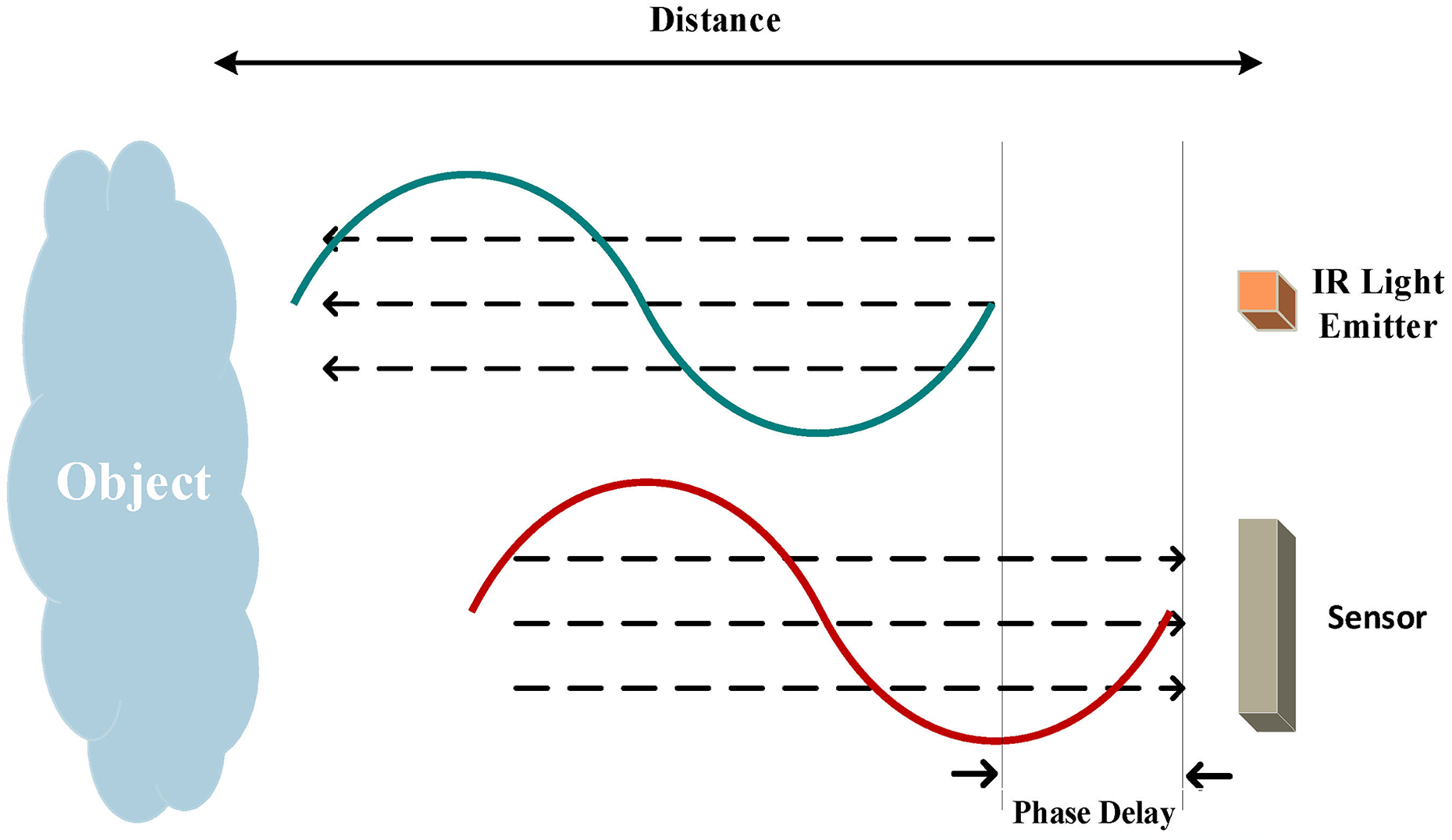
TOF principle. 166 TOF: time of flight.
where c is the speed of light, f is the frequency of the signal, and φ is the phase difference between the radiated and reflected IR signals
Some practical applications of this new sensing modality in 3D robot vision include robot navigation, 167,168 collision and obstacle detection, 169 mapping, 170 and 3D reconstruction. 171 The attractions of TOF technique include its low cost, the single-sensor measurement of depth directly without recourse to any form of the target, video-rate depth data collection, and its compact size.
3D sensors for robotics
Robots perform different tasks using intelligent vision sensors in different ways. In this section, we give an overview of popular 3D sensors embedded in robots, as shown in Table 2.
The latest 3D sensors for robotics.

3D: three-dimensional; IMU: inertial measurement unit; TOF: time of flight.
Future trends
Although 3D robot vision has been developed in many applications, the techniques are still not mature and perfect. With the progress of software and hardware technology, the core techniques such as object recognition, location, mapping and planning need to be constantly updated. More and more complex application demands appeared constantly due to the development and progress of human society. Vision companies and researchers are exerting efforts not only in the new vision techniques, but also in improving the applications mainly in the following aspects.
Smart sensor for intelligent recognition
Visual recognition plays a crucial role in technology and platform support. From the perspective of the whole robotic vision chain, it can be divided into three steps: imaging, perception, and understanding. Imaging is taking photographs. Perception involves acquiring content in images via sensors and acquiring perceptual input via algorithms. Understanding is actually based on visual recognition, such as in human–robot interaction, and the robots need to use intelligent robotic vision techniques to perform facial detection, facial recognition and the analysis of facial attributes to determine things like age and gender. 172,173 The widely used neural network has been applied to 3D object recognition inevitably (Figure 8).

Convolutional neural network for 3D object recognition. 174 (a) The VoxNet architecture. (b) Point cloud from three data sets. 3D: three-dimensional.
Event-sensitive vision sensor
The development of robotic vision is based on the existing framework, optimizing on the basis of predecessors and absorbing the latest achievements in other directions. The emergence of new sensors keeps robotic vision vigorous. If we can obtain high-quality original information directly, the calculation pressure will be reduced a lot in the next process. For example, the event camera, also called dynamic vision system (as shown in Figure 9), is gradually used in the 3D robotic vision system for scene reconstruction and tracking 176 because of its low power consumption and high frame rate. If the cost of this kind of sensor can come down, many changes will be brought into robotic vision.

Reconstruction based on event camera. 175 (a) Scene and DVS camera, (b) event stream, (c) estimated gradient map, and (d) reconstructed intensity map. DVS: Dynamic Vision Sensor.
Semantic SLAM by machine learning
Since the deep learning, invincible in many fields, many researchers tried to use the idea of end to end from deep learning to reconstruct the SLAM process. Some works have been done in replacing some processes of SLAM by deep learning, 177 –179 but these methods did not show landslide performance compared to the traditional geometric methods. In the near future, SLAM should absorb the achievements of deep learning and develop the accuracy and robustness constantly. Some parts of SLAM will be overall replaced by deep learning and a new framework will be formed.
Original SLAM focuses on the geometry information of the environment and the semantic information should be combined in the future. By means of deep learning technology, object detection and semantic segmentation techniques develop very fast. The abundant semantic information can be obtained from the images and aided for geometry inference, 180 as shown in Figure 10.

Semantic SLAM. 181 (a) Overview of the algorithm. (b) Initial map without recognized objects. (c) The tetra pack has been recognized, inserted, and is being tracked. SLAM: simultaneous localization and mapping.
Robot vision for medical applications
Robotic vision has been applied in important medical fields as a critical technology, such as the beating heart tracking based on stereo endoscope, 38 3D shape reconstruction for laparoscopy, 67 clinician detection using RGB-D data 182 as shown in Figure 11, vision-based navigation for capsule endoscopy, 183 and deep venous thrombosis detection using RGB-D sensor. 184 In clinical medicine, the robotic vision system can provide data regarding benign birthmarks and malignant melanomas without having to remove the conspicuous birthmark by means of an operation.

Clinician detection using RGB-D data. 182 (a) The connectivity map when real 3D positions of the nodes are considered. (b) The corresponding depth map used to re-project points into 3D. (c) Pose estimation results, where white and magenta represent left and right arms, respectively. 3D: three-dimensional.
Cloud robotics
For a simple robot hand, even grasping an object requires a huge amount of processing and preprogrammed information. That means sophisticated systems like humanoid robots need very powerful computing capabilities. 185 However, cloud robotics has the potential to make massive gains. With the research in this area happening across the globe, access to a cloud computing infrastructure would give all kinds of robots the massive processing power and data they need to perform complex, compute-intensive tasks as shown in Figure 12. Let robots off-load things like image processing and voice recognition. More excitingly, it would make the possibility of downloading new skills feasible to deal with a new task. 186

Robots can benefit from the powerful computation, storage, and communication resources of the modern data center in the cloud. 185
Conclusion
This article summarizes the recent developments in 3D robotic vision, including tens of kinds of current 3D sensors. Representative works are listed for readers to have a general overview of state of the art. Typical vision techniques are addressed for industry-concerned issues; for example, 3D object representation and SLAM. Representative applications are also reported and a number of vision systems for solving visual acquisition problems are investigated.
Footnotes
Declaration of conflicting interests
The author(s) declared no potential conflicts of interest with respect to the research, authorship, and/or publication of this article.
Funding
The author(s) disclosed receipt of the following financial support for the research, authorship, and/or publication of this article: This work is supported by the National Natural Science Foundation of China (grant nos. U1509207, 61325019).