
Abstract
Hand-eye calibration is a fundamental step for a robot equipped with vision systems. However, this problem usually interacts with robot calibration because robot geometric parameters are not very precise. In this article, a new calibration method considering the rotation parameters of the robot pose is proposed. First, a constraint least square model is established assuming that each spherical center measurement of standard ball is equal in the robot base frame, which provides an initial solution. To further improve the solution accuracy, a nonlinear calibration model in the sensor frame is established. Since it can reduce one error accumulation process, a more accurate reference point can be used for optimization. Then, the rotation parameters of the robot pose whose slight errors cause large disturbance to the solution are selected by analyzing the coefficient matrices of the error items. Finally, the hand-eye transformation parameters are refined together with the rotation parameters in the nonlinear optimization solution. Some comparative simulations are performed between the modified least square method, constrained least square method, and the proposed method. The experiments are conducted on a 5-axis hybrid robot named TriMule to demonstrate the superior accuracy of the proposed method.
Introduction
The use of industrial robots is widespread in diverse machining operations, such as drilling, milling, and grinding. Compared with machine tools, machining robots have many advantages of large workspace, high degree of freedom (DOF), cost-effectiveness, and high flexibility. Hence, there have been attempts to use industrial robots for machining processes instead of machine tools. Recently, machining robots are expected to perform more complex tasks, such as low-volume automated production in unstructured environments. It requires the machining robots not only to have good machining performance but should be equipped with relevant measuring system to assist the robots to locate the machining position of workpiece. 1 –4 The commonly used measuring system in industry can be divided into contact measurement and noncontact measurement. Due to the complex and irregular surface profile of the workpiece, the contact measuring system is difficult to meet the needs of industry. The visual measuring system, as one of the widely applied noncontact measuring systems, is characterized by low cost, compact structure, easy integration, and installation and is capable of realizing multiple fields of view measurement when it is integrated into the robotic system and forms robotic visual measuring system. And the problems such as occlusion, shadow, and inefficient measurement data can be overcome. 5 There are many visual measuring systems, such as monocular vision, stereo vision, structured light, and fringe projection. Fringe projection measuring system has been widely used in surface and mold measurement, rapid prototyping, reverse engineering, industrial detection, and other fields due to its characteristics of fast measurement speed, high precision, strong system reliability, and large amount of acquired point cloud. To obtain three-dimensional (3D) point clouds of the workpiece accurately and fast to determine the machining information, such as the position of the workpiece relative to the robot end effector and the machining allowance, a 3D-vision sensor based on fringe projection is adopted into the machining robot.
Two kinds of calibration need to be performed before the robotic visual measuring system is used. One is visual system calibration 6 –8 that is used to determine the internal parameters of the camera (called camera calibration) and external parameters between two cameras (called stereo calibration) and describes the mapping relationship between 3D space coordinates and two-dimensional (2D) image coordinates. Usually, the visual measuring system has been calibrated in advance by producer. The other is hand-eye calibration, which is used to determine the transformation between vision sensor and robot end effector. In this article, hand-eye calibration aims to establish cooperation between hand and eye to assist machining robotic positioning. A typical process of measurement-assisted robotic machining is shown in Figure 1. In the measurement process (No. 1), a 3D-vision sensor mounted onto the end effector of a machining robot measures the workpiece to obtain the machining information in the vision sensor frame. Through hand-eye transformation (No. 2), the machining information under the vision sensor frame is transformed into the robot end-effector frame. Finally, according to the current position of the robot end effector and the machining information, the robot end effector is driven to the machining position to complete machining (No. 3). It can be seen that hand-eye calibration is a key step that accurately determine the position and pose relationship between vision sensor and robot end effector to ensure the machining accuracy of the robot.

Typical process of measurement-assisted robotic machining.
Essentially, hand-eye calibration is to solve the homogeneous transformation matrix between the vision sensor frame and the robot end-effector frame, also known as the hand-eye transformation matrix. There are many typical algorithms for solving the matrix, including screw theory, 9 quaternions, 10 dual quaternions, 11 Kronecker product, 12,13 and so on. According to the calculating process, hand-eye calibration methods can be divided into three categories. The first belongs to separable closed-form solutions, 14 –16 which is to solve rotation and translation separately. The rotation can be solved firstly by linear equations and then the translation is solved with the solved rotation. This kind of method is simple in derivation and convenient in solution, but the error of estimated rotation will propagate into the solution of the translation. It is sensitive to the noise in the collected data. The second belongs to simultaneous solutions, 17 –19 which is to solve rotation and translation simultaneously. Obviously, there is no error accumulation problem in this kind of method, but the rotation estimated cannot guarantee the orthogonality, 20 such as Kronecker product method. The rotation can be further optimized to satisfy the orthogonality, but the translation cannot meet the accuracy requirement. The third belongs to iterative solutions, 21 –23 which is to solve rotation and translation simultaneously by optimizing iteratively the objective function established. This kind of method usually has high accurate solution but is complex and time-consuming. In addition, the accuracy of solution depends on the initial value for iteration. Choosing wisely, linear method is generally adopted for estimating initial value and followed by iterative optimization for accurate solution.
In summary, various hand-eye calibration methods have been developed and tremendous progress has been made in solving hand-eye transformation matrix. However, most researchers only focus on the solution of the hand-eye matrix by different mathematical tools or how to avoid error accumulation during the solution. The effects of the robot pose error on the solution accuracy are not fully considered in their methods which are applied only in the case of low accuracy requirement. Some researchers have proposed to calibrate the hand-eye and the robot simultaneously, 24,25 which leads to complicated derivation and may arise linear correlation problems in parameter estimation. Especially for parallel or hybrid robots, the error modeling is actually a complicated problem. 26,27
This article aims to guide the positioning of machining robots using a 3D-vision sensor, which is integrated at the end effector of machining robots. An accurate hand-eye calibration method only considering the rotation parameters of the robot pose is proposed. The hand-eye calibration model is simple and easy to establish. In addition, the linear correlation problems are avoided through the parameter analysis. The main contributions of our work are summarized as follows: A constrained least square solution is introduced to provide good initial values for the next step of optimization. A nonlinear optimization solution that further improve the solution accuracy is presented simultaneously to optimize the rotation parameters that have a significant impact on the solution accuracy. Simulations and experiments are conducted to compare the three different methods and demonstrate the superiority of the proposed method (PM).
The article is structured as follow. The second section introduces robotic visual measuring system, coordinate system and coordinate transformation, and conventional calibration method. In the third section, the PM of hand-eye calibration is presented and parameter analysis is also performed to discuss the effects of different parameters on the solution accuracy. Some simulation and experimental results are detailed in the fourth section, and the article ends with concluding remarks in the fifth section.
Background knowledge
Robotic visual measuring system
As shown in Figure 1, robotic visual measuring system is mainly composed of a 5-axis hybrid robot and a 3D-vision sensor. The 3D-vision sensor is mounted onto the A/C type wrist of the 5-axis hybrid robot, which can be considered as being fixed in spatial position with the end effector of the robot. In the working process of the system, the 5-axis hybrid robot cooperates with the 3D-vision sensor. After the robot moves to the designated position, the sensor performs the measurement function. After the measurement, the robot moves to the next designated position, and the sensor continues the measurement, and so on, until the whole measurement task is completed. Finally, the measured data of multiple robot poses are unified in the same coordinate frame, which generally is the workpiece coordinate frame, and the complex surface profile is reconstructed or the end effector of the robot is adjusted to the specified position for machining according to the measurement information. TCP/IP protocol is adopted to construct data communication between the robot and the vision sensor, which can implement real-time control.
The 3D-vision sensor consists of three sensors, which are two industrial charge coupled device (CCD) cameras and a digital light processing projector, as shown in Figure 2. The measurement principle is based on fringe projection profilometry. First, multifrequency fringes are projected onto the object, which is deformed by the depth change of the object and modulates the depth information into the fringes. At the same time, two CCD cameras on the left and right capture the deformed fringe images and transmit the images to data processing system. And then through phase analysis and phase unwrapping, the same imaging points of object in the left and right camera planes can be matched. Finally, 3D information of the object is recovered according to the system configuration parameters.

Schematic diagram of 3D-vision sensor. 3D: three dimensional.
Coordinate system and coordinate transformation
As shown in Figure 3, hand-eye calibration mainly involves three coordinate frames: 3D-vision sensor frame (called sensor frame for short [SF]), robot end-effector frame (called end-effector frame for short [EF]), and robot base frame (called base frame for short [BF]). The origins of these coordinate frames are S, E, and B, respectively.

where the rotation matrix


Schematic diagram of hand-eye calibration.
A standard ball is placed in the robot workspace for calibration, the position of which is guaranteed to be fixed. P is the spherical center.
After the robot moves to a certain position, the sensor scans the standard ball and obtains the coordinate of spherical center. The relationship that the coordinate of the spherical center is transformed from the sensor frame

where
Conventional calibration method
When the robot moves to different positions and the sensor scans the standard sphere simultaneous, we can obtain the following equations 24

Since the position of the standard ball relative to the robot base remains invariable, without loss of generality, the first measurement of the spherical center in the base frame is regarded as the reference point, and the following constraint equations can be established

By handling equation (5), we can obtain

where

According to equation (4), multiple equations similar to equation (6) can be obtained. The least square solution of hand-eye transformation parameters obtained is as follows

Since no constraint is imposed on the rotation of the hand-eye transformation matrix for solution, the rotation estimated is not orthogonal. The direct method is to rearrange the rotation
where

The

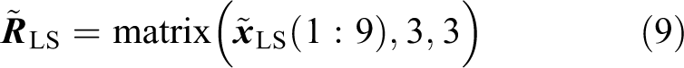
The results with corrected rotation matrix are referred as modified least square solution

Proposed method
Constraint least square solution
The translation
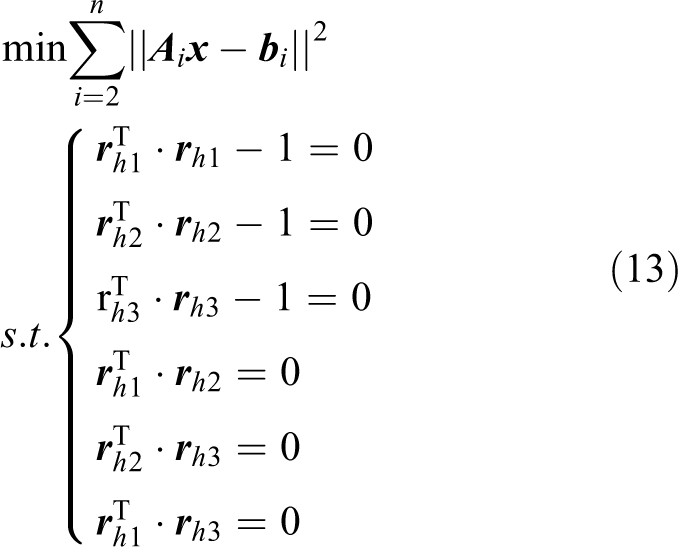
where ‖‖ denotes the Frobenius norm. This model is solved by introducing Lagrange multipliers 28 and the constraint least square solution is given as

where
Nonlinear solution considering the rotation parameters of the robot pose
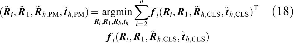
According to equation (5), the accuracy of the reference point in the base frame is affected by both the measurement error of the sensor and the robot pose error. To obtain a more accurate reference point, the first measurement of the spherical center in the sensor frame can be referred as the reference point. As the accuracy of the reference point is only affected by the measurement error and one error accumulation process is reduced, the accuracy of the reference point in the sensor frame is higher than that in the base frame, which provides the possibility to make a better estimation for the hand-eye transformation parameters. However, the measurement by the sensor transformed from the sensor frame under other robot poses to the sensor frame where the reference point is located suffers from more error propagation and error accumulation. Therefore, additional parameters are introduced to reduce the effects of the errors on the solution accuracy. In addition, excessive additional parameters will lead to linear correlation between the parameters and reduce the accuracy of the solution. It is necessary to analyze the effects of all the candidate parameters on the solution accuracy. Through the parameter analysis in the “Parameter analysis” section, we observed that slight errors of the rotation parameters can cause large amount of error. Hence, the rotation parameters of the robot pose are regarded as the additional parameters and are optimized in a nonlinear calibration model together with the hand-eye transformation parameters. Based on the reference point in the sensor frame, the nonlinear calibration model is established as follows

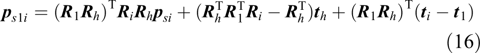
where

This is a nonlinear optimization problem, which is solved using Levenberg-Marquardt (LM) algorithm. 29 Nonlinear optimization requires a good initial value to ensure the accuracy of the solution. Here, the constraint least square solution in equation (14) is used as the initial values. We can obtain
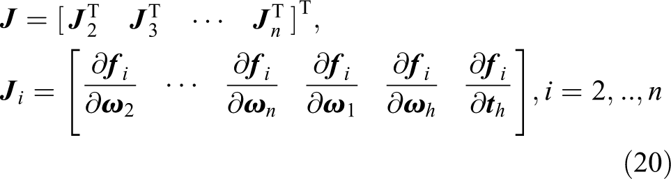
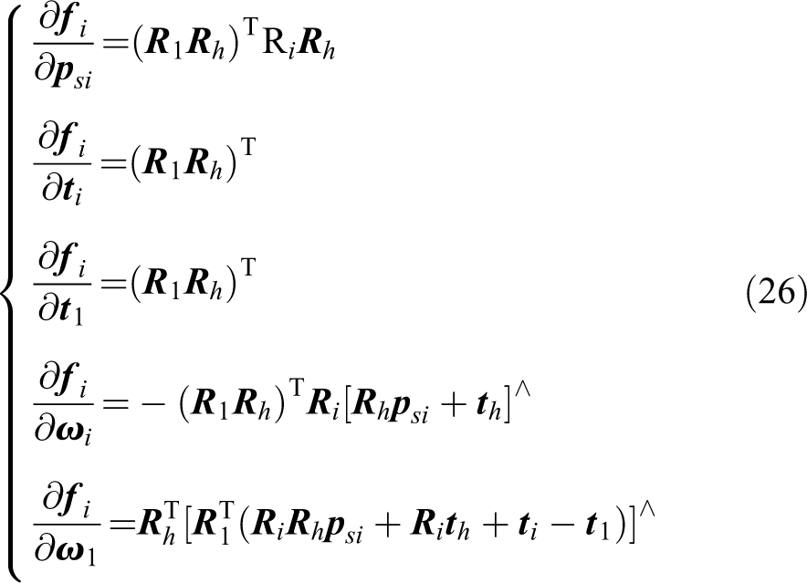
where

where


The obtained

The iterative process does not terminate until the variation of
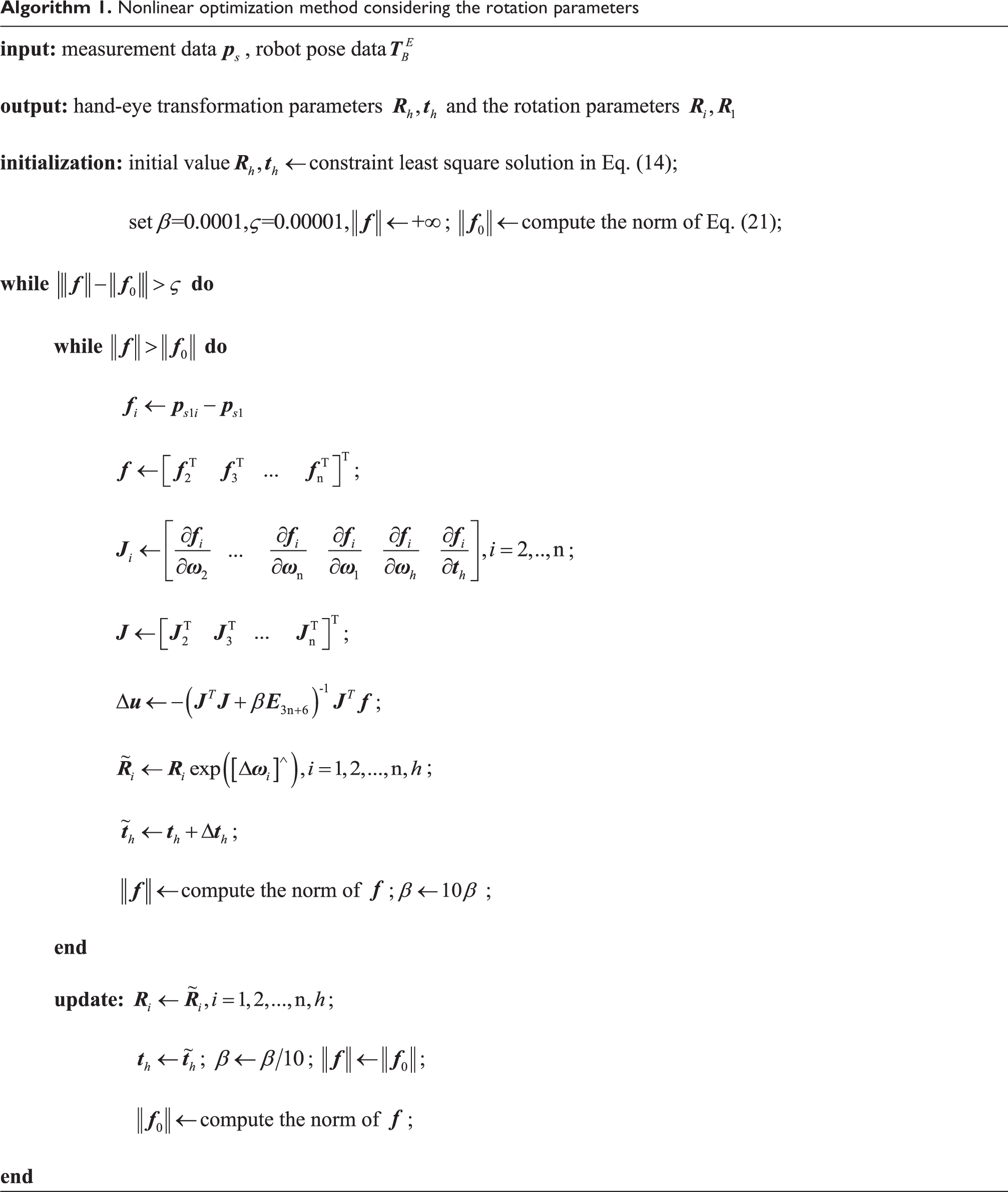
The PM is concluded in Algorithm 1:
Nonlinear optimization method considering the rotation parameters

Parameter analysis
In this section, parameter analysis is carried on to select the key parameters that have a great impact on the solution accuracy of hand-eye transformation parameters. The key parameters will be as additional parameters and optimized together with the hand-eye transformation parameters to improve the solution accuracy.
It has been proved
30
that the solution accuracy is related to the condition number of the Jacobian matrix

where
In addition,

where
Observe the constitution of
Simulations and experiments
Some simulations and experiments are carried out to verify the effectiveness of the PM. The PM is compared with the modified least square method (MLS) and the constraint least square method (CLS) under different aspects.
Simulations
The simulations are performed to compare the performance of the three methods described in this article from noise level and data bulk. The true values of the hand-eye transformation parameters
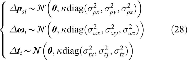
where


where (a) Noise level
We set 10 noise levels and randomly select 20 sets of data to estimate the hand-eye transformation matrix with the three methods described above under each noise level; 500 trials are carried out under each noise level to get the average error of rotation and translation. The simulation results are shown in Figure 4. It shows the rotation error and translation error of the three methods at different noise levels.

Rotation error and translation error at different noise levels.
It can be seen that with the increase of noise level, the rotation error and the translation error of the three methods increase. In terms of solving the rotation matrix, the accuracy difference of the three methods is not obvious, while in solving the translation vector, the accuracy of the PM is significantly better than the other two methods. (b) Data bulk
We select different amounts of data (m = 10, 20…100) to estimate the hand-eye transformation matrix using the three methods under low, medium, and high noise levels. Similarly, 500 trials are carried out under each noise level and the same amount of data to get the average error of rotation and translation. The simulation results are shown in Figure 5. Figure 5(a) to (c) shows the rotation error and translation error of the three methods with different amounts of data under low, medium, and high noise levels, respectively.

Rotation error and translation error with different amounts of data: (a) low noise level, (b) medium noise level, and (c) high noise level.
The simulation results indicate that the rotation error and the translation error of the three methods decrease with the amount of data increasing under each noise level. The accuracy improvement of the three methods is the most obvious when the amount of data becomes from 10 to 20. When about 40 sets of data, the accuracy improvement rate slows down significantly.
In terms of solving the rotation matrix, the PM is slightly better in accuracy than the other two methods before 20 sets of data. After 30 sets of data, MLS becomes the best in accuracy, and the PM is almost the same as CLS in accuracy.
In terms of solving the translation vector, the PM shows excellent advantages in accuracy. The accuracy difference between CLS and MLS gradually becomes smaller.
According to the simulation results of noise level and data bulk, the PM outperforms in the accuracy of the hand-eye transformation matrix than MLS and CLS. Balancing accuracy and efficiency in practical applications, it is recommended to select about 20 sets of data to estimate hand-eye transformation matrix.
Experiments
(a) Experimental setup
The experimental setup mainly consists of a 5-axis hybrid robot called TriMule (averaged repeatability 0.02 mm), a 3D-vision sensor developed by the research team of Tianjin University (field of view 170 mm × 170 mm), a designed artifact with known dimensions and data processing system, as shown in Figure 6. The artifact has two standard balls, ball A with the diameter of 19.9886 mm, ball B with the diameter of 19.9878 mm, whose center distance between the two balls is 59.8573 mm. The data processing system monitors the measurement state in real time and guarantees the measurement quality of the 3D-vision sensor. It also provides images and 3D-point cloud display.

Experimental setup.
(b) 3D-vision sensor accuracy test
Before verifying the calibration method, the measurement accuracy of the sensor should be tested. The artifact is measured by the sensor from different positions, and the 3D-point cloud of the artifact is obtained. The diameter of ball A and ball B and the center distance between the two balls are calculated by fitting the point cloud measured. By comparing the calculated value with the standard value of the artifact, we can evaluate the measurement accuracy of the sensor. The measurement experiment of the artifact is shown Figure 7. The measurement results are listed in Table 1. Mean absolute error (MAE) represents the deviation between the measured value of the sensor and the truth value. Standard deviation (SD) represents the dispersion of the measurement data. MAE of ball A diameter, ball B diameter and the center distance is 0.0150 mm, 0.0101 mm, and 0.0058 mm, and SD is 0.0041 mm, 0.0094 mm, and 0.0045 mm, respectively, indicating that the accuracy of the sensor is enough high for the hand-eye calibration.

Measurement experiment: (a) measurement of the artifact and (b) 3D-point cloud of the artifact. 3D: three dimensional.
Measurement results of the artifact.

SD: standard deviation; MAE: mean absolute error.
(c) Measurement-assisted robotic positioning
To compare the accuracy of the three methods, the hand-eye calibration experiment is carried out with the ball A of the artifact, and the hand-eye transformation matrix is calculated using the three methods. An important application of hand-eye calibration is to assist robotic positioning with vision sensors. Under the same conditions, the accuracy of auxiliary robotic positioning reflects the accuracy of hand-eye calibration. Hence, an analog experiment is designed to simulate the robotic positioning process of assisted by the 3D-vision sensor. By comparing the positioning accuracy, the accuracy of the three methods in solving the hand-eye transformation matrix can be indirectly evaluated.
The artifact is placed at a position in the robot workspace. The ball A of the artifact is measured by the sensor from one robot pose, and the ball B is measured from the other robot pose. The spherical center coordinates of ball A and ball B are transformed from the sensor frame to the base frame, respectively. The spherical center coordinates of ball A in the base frame are regarded as the starting point, and the center coordinates of ball B are regarded as the target point for positioning. The positioning error


where
The artifact is placed at 20 different positions in the robot workspace. The positioning errors are shown in Figure 8. The maximum/mean positioning errors are 0.1133/0.0367 mm (MLS), 0.0961/0.0278 mm (CLS), and 0.0703/0.0244 mm (PM), respectively. It can be seen that the positioning errors with the PM get lower than that with the other two methods.
Positioning error at different positions of the artifact.
(d) Point cloud registration
Another important application of hand-eye calibration is to associate point clouds of the workpiece measured from different robot poses into a common coordinate frame to reconstruct the 3D model of the workpiece. Similarly, the accuracy of the three methods can be indirectly compared through the accuracy of the 3D model reconstructed.
The artifact is placed at a position in the robot workspace and measured by the sensor from two different robot poses. Both sets of point clouds are transformed from the sensor frame to the base frame and are stitched together to get the stitched model. The diameter of ball A and ball B of the stitched model can be calculated and be compared with the standard value of the artifact to get the diameter errors. The point cloud registration process is shown in Figure 9.

Point cloud registration process.
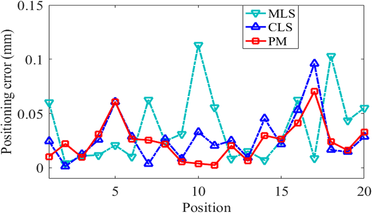
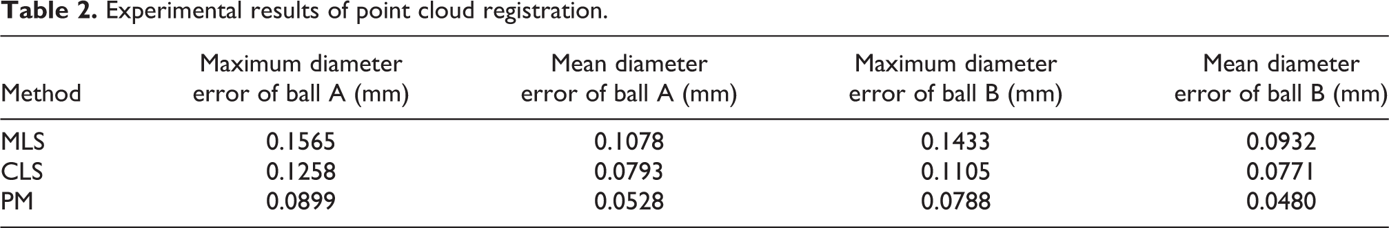
The artifact is placed at 20 different positions in the robot workspace. The diameter errors of ball A and ball B are shown in Figure 10. The experimental results of point cloud registration are summarized in Table 2 and further demonstrate the superiority of the PM.

Diameter error of stitched point cloud at different positions of the artifact: (a) ball A and (b) ball B.
Experimental results of point cloud registration.
Conclusions
To guide the positioning of the machining robots, a 3D-vision sensor is integrated at the end effector of machining robots and form the robotic visual measuring system for positioning and measurement. We have proposed an accurate hand-eye calibration method to determine the transformation between the sensor and the robot end effector. A hand-eye calibration model is established in the sensor frame and is capable of providing the more accurate reference point for the solution of hand-eye transformation parameters. A nonlinear optimization algorithm has been proposed. It is implemented with the consideration of the effects of the robot pose error, where it should be necessary to consider in high precision robotic machining. To avoid the linear correlation problems, parameter analysis is performed and the rotation parameters of the robot pose having a significant impact on the solution accuracy are selected as additional parameters to be optimized. A constraint least square solution has been given and provides good initial values for optimization. The simulation results on noise level and data bulk demonstrate that the PM has higher accuracy in solving hand-eye transformation matrix than MLS and CLS. Positioning and measurement experiments are designed and are carried out on a 5-axis hybrid robot named TriMule. The maximum/mean positioning errors have been reduced from 0.1133/0.0367 mm (MLS), 0.0961/0.0278 mm (CLS) to 0.0703/0.0244 mm (PM) in the positioning experiment, and the maximum diameter errors of ball A and ball B have been reduced from 0.1565/0.1433 mm (MLS), 0.1258/0.1105 mm (CLS) to 0.0899/0.0788 mm (PM) in the point cloud registration experiment. The experimental results further prove the superiority of the PM over MLS and CLS in terms of positioning accuracy and point cloud stitching accuracy. Additionally, the measurement accuracy of the 3D-vision sensor is also tested.
In the future work, we will fix the machining robot on a mobile platform and develop a mobile robotic machining system for large complex components. The calibration method will be investigated to ensure global positioning of the mobile robot.
Footnotes
Declaration of conflicting interests
The author(s) declared no potential conflicts of interest with respect to the research, authorship, and/or publication of this article.
Funding
The author(s) disclosed receipt of the following financial support for the research, authorship, and/or publication of this article: This work is supported by National Key Research and Development Program (Grant No. 2017YFE0111300), National Natural Science Foundation of China (Grant No. 51721003 and No. 51775376), and EU H2020 project (Grant No. 734272).