
Abstract
The 3D assembly of micro-/nano-building blocks with multi-nanomanipulator coordinated manipulation is one of the central elements of nanomanipulation. A novel rail-guided nanomanipulation system was proposed for the assembly of a cellular vascular-like hydrogel microchannel. The system was equipped with three nanomanipulators and was restricted on the rail in order to realize the arbitrary change of the end-effectors during the assembly. It was set up with hybrid motors to achieve both a large operating space and a 30 nm positional resolution. The 2D components such as the assembly units were fabricated through the encapsulation of cells in the hydrogel. The coordinated manipulation strategies among the multi-nanomanipulators were designed with vision feedback and were demonstrated through the bottom-up assembly of the vascular-like microtube. As a result, the multi-layered microchannel was assembled through the cooperation of the nanomanipulation system.
1. Introduction
Nanomanipulation, or control of matter on the nanometric scale, has become the most significant enabling technology and plays an important role in scientific disciplines as diverse as physics, chemistry and biology [1]. Through manipulation, ranging from single atom to molecular group, nanomanipulation techniques open a novel route to the analysis of material properties on the nanoscale and advance the relevant fabrication techniques for special devices [2]. Many kinds of nanomanipulation system have been developed under different microscopes. Through the utilization of electrical, magnetic and optical forces, researchers can manipulate the mesoscopic building blocks with non-contact manipulation systems [3–4]. By contrast, the mechanical force-based systems realize manipulation through direct contact between the mechanical end-effector and the specimen [5–6]. Through this direct contact, without the restriction of the operating environment interfering electrically or optically, the direct-contact nanomanipulation system can provide more stable and flexible manipulation with larger force [7]. The atomic force microscopy (AFM) cantilever and micro glass pipette with a controllable tip shape of the order of a nanometre, have become the typical end-effector of the contact nanomanipulation system. Through the manipulation of the tip on the surface of the specimen, the observation, analysis and assembly of the mesoscopic 3D structures can be achieved [8–9].
The 3D assembly of mesoscopic building blocks, as the most central part of nanomanipulation, has been applied in manufacturing and biomedical research [10]. Considering the direct-contact nanomanipulation for 3D assembly, nanomanipulators need to work in a relatively large 3D space with nanoscale positional resolution to realize the handling, modification and connection of the structures [11]. The current manipulation systems for assembly are mainly based on manual operation and remote control, which are time-consuming and experience-dependent. The automatic nanomanipulation systems have been developed to improve efficiency during the 3D assembly of nanodevice prototypes and other mesoscopic constructs [12]. However, most of them equip a single manipulator with stationary substrate. Without the coordination of multiple end-effectors, the integration and application of sophisticated assembly strategies are limited. In terms of 3D assembly with direct contact, the approaching posture and manipulation direction of the end-effectors need to be arbitrarily changed during nanomanipulation. However, it is difficult for the robotic system with stationary substrate to change the manipulation posture without moving out of the visual field [13]. To achieve the industrialization of 3D assembly of nano-sized building blocks, a novel nanomanipulation system with multiple end-effectors for complex operations needs to be developed.
The 3D assembly of cellular structure, as one of the key applications of the nanomanipulation system, plays an important role in tissue engineering. Tissue engineering is the innovative biomedical technology which generally works towards achieving the goal of harvesting human tissues through in vitro cultivation [14]. Through the fabrication, cultivation and transplantation of the substitute tissue, it can restore, maintain or improve human tissue function. The traditional fabrication methods to engineer tissue are scaffold-based [15]. Researchers seed the expected type of cells on the scaffold, which serves as an artificial extracellular matrix for penetration, ingrowth, and vascularization [16–17]. Through the biodegradation of the scaffold and the growth of the cells at the ratio, the biological substitute can be achieved [18]. However, the lack of control and manipulation on the nanoscale makes it difficult to fabricate the 3D tissue with microscaled structures [19]. As a novel method for the fabrication of cellular building blocks, 3D assembly with nanorobotic manipulation can generate the complex biological substitute from the bottom up. Through the coordinated manipulation among multi-manipulators, the positioning, immobilization and connection of cellular microstructure can be achieved. As a result, the engineered tissue can keep the function of a 3D structure and also its microstructural features. For most of the nanorobotic systems, the main issue is how to realize the design and integration of the system with both precise control and flexible cooperation [20]. The development of a multi-robotic nanomanipulation system with sophisticated, coordinated manipulation incorporated in it must be addressed for 3D assembly on the nanoscale [21–22].
In this paper, we propose a novel rail-guided multi-robotic system with coordinated nanomanipulation for the 3D assembly of the cellular microstructure. The robots were restricted on the rail and achieved the arbitrary change of approaching posture through concentric movement along the rail. The biocompatible hydrogel, providing the assembly modules, was solidified through UV exposure and the cells encapsulated inside. Through the coordinated manipulation among the multi-robots with vision feedback, assembly strategies with operational resolution of around 30 nm were achieved for the fabrication of a 3D cellular vascular-like microchannel.
2. Multi-robotic nanomanipulation system for 3D assembly
2.1 Basic concept of 3D cellular assembly with nanomanipulation
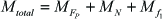
The basic concept of assembling the 3D hydrogel structure with rail-guided multi-robotic system is shown in Figure 1. Instead of directly building the microchannel as a whole, we assembled the two-dimensional (2D) cell-embedded micro-modules from the bottom up. After fabrication of 2D modules, the 3D cellular microstructure was achieved by assembly of those 2D modules using coordinated manipulation among multiple robots and the co-culture of the assembled cellular microchannel. To maintain cell viability during nanomanipulation, the expected type of cells were first mixed with the biocompatible hydrogel and fabricated to the 2D modules for assembly. Based on the sensitometric properties of the hydrogel, we fabricated different shapes of 2D module based on the solidification of hydrogel by exposure to different shapes of UV light. The 2D modules were collected and observed under the inverted optical microscope (OM). Through the coordinated assembly of the modules layer by layer, the multi-robotic system realized the fabrication of 3D hydrogel microstructures. The image acquired from the OM was processed as the vision feedback. Through the concentric movement of every robot along the rail, the approaching posture of the end-effector and the manipulation direction during assembly were arbitrarily changed, which strongly improved flexibility and efficiency during assembly. As a result, the assembled 3D cellular structure was moved to the incubator for co-culture and harvesting. This kind of 3D structure can be used as the biological substitute for human tissue in tissue engineering and regenerative medicine in the future.

A schematic drawing of 3D cellular structure assembly with rail-guided multi-microrobotic system
2.2 Rail-guided multi-robotic system set-up
To realize the arbitrary change of the end-effector direction during assembly, we developed the movable, rail-guided, multi-robotic nanomanipulation system instead of the stationary manipulation system. As shown in Figure 2, the nanomanipulators were modularized and set up on the rail, which means that the anticipated number of end-effectors can be integrated into the system to improve cooperation during assembly. In our system, three nanomanipulators were mounted on the rail and the whole system consisted of three subsystems, including rough control, fine control and the vision feedback subsystem. The rough control system was designed to achieve both the large operating space and the arbitrary change of the end-effector postures. The stages, combined with a stepping motor (model 398867, Maxon Motor Inc.), were mounted on the rail. Through the driving of the stepping motor, the concentric movement along the rail was demonstrated, which rotated the end-effector of the robots without swapping the tip out of the visual field. This benefited the visual tracking and coordinated manipulation during assembly. Considering every nanomanipulator in the stage, the piezo motor (model 8353, New Focus Inc.) was utilized for fine control. With the driving of the piezo motor along the X-Y-Z direction, every nanomanipulator can achieve the nanoscale operation resolution of around 30 nm in 3D space. A micro-glass pipette as the end-effector of the nanomanipulator (P-2000, SUTTER Inc.) was pulled to shape the tip with a microscale size of around 10 μm and was integrated to the robot. To improve the efficiency and robustness of the multi-robotic system during assembly, the vision feedback system was developed based on the processing of the image acquired from the OM. The target was located and the distance information was sent back to the system for task optimization. Through the combination of these three subsystems, the bottom-up assembly of the 3D microstructure with sophisticated nanomanipulation was realized.

Setup of the multi-microrobotic system under optical microscope
2.3 Kinematic analysis of the multi-robotic system
As mentioned, the multi-robotic system needs to work in a relative large 3D space with nanoscale positional resolution during the assembly of 3D hydrogel microstructures. In our system, every robot on the rail is configured with four degrees of freedom (DOFs), as shown in Figure 3. The first revolute joint was derived from the concentric movement along the rail by the stepping motor, and the other three prismatic joints along the X-Y-Z direction were derived from the piezo motor's translation movement. To realize the kinematic analysis of the multi-robotic system, we fixed the frames for every joint. As shown, the frame 0 was fixed on the stage. The frame 1 was fixed on the revolute joint which can achieve the rotation in the Z1 direction. The frames 2, 3 and 4 were fixed on the prismatic joint which can translate in their Z directions. Frame 5 was the tool frame which was fixed on the tip of the glass pipette. The product of all five link transformation matrices can be described according to the Denavit-Hartenberg parameters, which are given by:

Kinematic analysis and frame alignments for the nanomanipulator

where


where Li (i=1, 2, 3) was the constant height of the piezo motor module and dx (x=1˜4) was the translational movement of every prismatic joint, which is a variable value. R is the radius of the rail. The angle θ1 was determined by the concentric rotation along the rail. It was a constant during the movement control of the pipette tip, since the posture of the tip was set by the rotation in advance. Thus, the movement of the glass pipette in the X-Y-Z direction can be easily controlled by the piezo motors.
To realize the 3D assembly of the hydrogel microstructure, every nanomanipulator in the rail-guided system needs to be competent to approach and make contact with the target in every direction, which means that the nanomanipulator should have a relative large operating space. We calibrate the operating space of the end-effector for every nanomanipulator after the frame assignment. In our experimental setup, the height of every piezo motor module Li was set to 20 mm, the translational movement range dx for the piezo motor was fixed to 12.7 mm and the designed rail had the radius R of around 50 mm. As a result, the operating space of the end-effector was calibrated with Matlab. Figure 4 shows the 3D view and the top view of the operating space. Considering every nanomanipulator, the operating space in the X-Y-Z direction was given by:

Calibration of operating space with Matlab


For nanomanipulation of the hydrogel 2D modules with a size no larger than 400 μm, an operating space with nanoscale positioning resolution in 3D space was desirable.
3. 3D assembly of the cellular hydrogel with multi-robot
To assemble the 3D hydrogel microstructure with coordinated nanomanipulation of the multi-robotic system, the assembly units need to be pre-fabricated and the control method during the assembly should be addressed to ensure robustness and efficiency. In this part, we fabricated the 2D cellular hydrogel modules in the microfluidic channel and developed the control system with vision feedback. Finally, the basic pick-up success rate was analysed.
3.1 On-chip fabrication of cellular hydrogel modules
Instead of direct contact with cells, the cells were encapsulated into the 2D hydrogel modules for assembly with multi-robotic coordinated manipulation. The size of the assembled structure can be easily regulated through controlling the total number of the 2D hydrogel modules in the assembled array. Through the soft contact between the hydrogel and the cells, cell viability during assembly can be maintained.
As shown in Figure 5, we utilize the microfluidic channel to fabricate the 2D modules. The fabrication method is based on the sensitometric characteristic of the cross-linkable hydrogel [23]. After exposure with UV light, the cell-mixed hydrogel solution can solidify and encapsulate the surrounding cells into the structure. The shape of the solidified 2D module is determined by the profile of the UV light it is exposed to. To achieve predefined physiological architectures, the UV light source was covered with different masks to shape different profiles of the 2D module. Finally, the 2D modules were collected by the buffer solution for 3D assembly.

On-chip fabrication of the cellular hydrogel modules
The NIH/3T3 cell, as one type of fibroblast, forms the outer layer of the vessel, so we chose it for 2D module fabrication. The Poly(ethylene glycol) diacrylate (PEGDA, molecular weight 700, Sigma Aldrich), as one type of cross-linkable hydrogel, is biocompatible and exhibits mechanical properties similar to those of soft tissues, so PEGDA was utilized for the encapsulation of NIH/3T3 cells for 2D module fabrication. Prior to the experiment, cells were cultured inside Dulbecco's Modified Eagle's Medium (DMEM, Sigma Aldrich) with 10 % Foetal Bovine Serum (FBS, Sigma Aldrich) for 72 hours and mixed inside Phosphate Buffered Saline (PBS, Wako) to form a PBS cell solution of 107/mL cell concentration. The experimental solution was formed by 272 μL PBS cell solution, 120 μL PEGDA and 8 μL photoinitiator (Irgacure 2959, Ciba). As shown in Figure 6, after the exposure of UV light to the PEGDA, different shapes of 2D module were solidified and the NIH/3T3 cells were encapsulated in the module. For the assembly of complex architecture, more types of cells can be embedded into different 2D shapes.

The fabricated 2D hydrogel modules embedding cells inside themselves
3.2 Control of the multi-robot based on vision feedback
The 3D hydrogel assembly is based on the basic pick-up manipulation of the 2D modules, which is time-consuming and experience-dependent. To improve efficiency and robustness during the assembly, we developed a control system with vision feedback during the pick-up and assembly of the cellular 2D modules with the multi-robot.
To acquire the image information as vision feedback, the image from the OM was utilized as the original image for processing during assembly. As shown in Figure 7, images of different situations were processed, including manipulation with a single nanomanipulator and with a multi-nanomanipulator. Since the 2D modules were placed in the buffer solution in different states, the image was optimized to eliminate the disturbance derived from the open operation environment and the ideal 2D target was chosen for the pick-up. As shown, grey processing and binarization processing were utilized to eliminate the disturbance from the environment. For the situation with a single nanomanipulator, the profile of the glass pipette and the eligible 2D donuts were identified in the blob image. To choose the ideal donut target, the vision system set the filtration rules and optimized the image further. The vision system defined the donuts which lay evenly on the bottom of the plate as the donuts with the best pick-up posture, and located the donut closest to the tip of the pipette as the ideal target. To realize this function, the Hough transformation was utilized to recognize the donut's circle and the straight outline of the pipette. Through the sequential scanning of the pipette outline, the tip was located. After the comparison of the circle in blob image, the centre of the ideal donut target was determined. As shown in Figure 7(d), the tip of the pipette and the centre of the ideal donuts were marked as the start point and target point. The relevant distance and location information was sent back for movement control. For the manipulation situation with a multi-nanomanipulator, the same processing method was applied for the elimination of disturbance. Additionally, the template-matching technique in (8) was utilized to locate all the tips of the multi-nanomanipulator. As shown in Figure 7(g), all the tips were located and the main manipulator which was closest to the qualified donut was defined in Figure 7 (h). In order to provide feedback information for manipulation control, the moving distance calibration between the main manipulator and the qualified 2D module was implemented so as to obtain the control value K for 3D assembly.

Image processing of the multi-robotic system during 2D hydrogel module assembly

As shown in Figure 8, after the design of the vision feedback, all the control sequences during the 3D assembly with nanomanipulators were developed. First, the real-time image was captured and processed. After image processing, the target position was set and the current distance was calculated as the movement control feedback. During movement control, the image was updated and the new distance was calculated again in real time. Finally, the automatic pick-up of the 2D modules based on the microrobotic control system was achieved.

Flow chart of the nanomanipulation control with vision feedback
Since the donuts were collected in the petri dish and the whole assembly procedure was established in the buffer solution, the movement of the multi-nanomanipulator might disturb the surrounding solution and change the posture of the target donut. To maintain the posture of the target 2D module and ensure the pick-up success rate, the speed control between the tip of the end-effector and the target donut was designed based on the vision feedback. As shown in Figure 9, the speed control method based on distance was utilized to make the movement control intelligent. The tip of the pipette moved at a maximum speed when the distance to the target donut was long in order to reduce the movement time. By contrast, the movement speed decreased to a relatively low value to ensure precision when the distance was short. As a result, the automatic approach of the nanomanipulators to the target donut was realized.

Movement control of the glass pipette based on the distance information
3.3 Immobilization of the cellular hydrogel modules
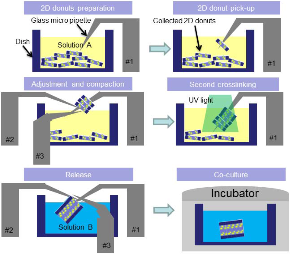
As mentioned in relation to the basic concept of 3D assembly, in order to fabricate the cellular 3D hydrogel structure, the pick-up manipulation for gathering the 2D modules layer by layer on the main manipulator was a key part of the assembly. Based on the contact manipulation between the main manipulator and the 2D module, we developed a pick-up strategy which only needs the upward and downward movement of the main manipulator to pick up the 2D modules. As shown in Figure 10, the main manipulator only needed to approach in Z-axis to press the donut. Because of the torque during the press, the donut flipped and lay on the glass pipette. The torque which caused the flipping of the donut was increased during the press. The further approach of the main manipulator caused the deformation of the tip and shortened the distance between the ground and the shaft part. As a result, the picked up donut moved to the shaft part of the main manipulator without the help of the sub-manipulator. The main manipulator moved upwards and repeated the rotation with another donut. The mechanical analysis of where the rotate happened was realized. The relevant equations to determine the torque were expressed as:

Mechanical analysis of the donut during rotation

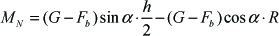


where Fp is the press force from the manipulator to the donut, f1 is the friction force between the manipulator and the donut and G and Fb are the normal forces which are determined by material characteristics. The total torque is determined by the cooperation of these four forces. As a result, through the downward manipulation that changes the press force Fp, the total torque can be increased and the donut finally rotates and lies on the manipulator. To pick up donuts with the same thickness, the manipulator only needs to repeat the upward and downward movement with the same vertical distance, an aspect that strongly improved the micro-assembly efficiency.
3.4 Experimental analysis of the cellular hydrogel immobilization
According to the mechanical analysis of the pick-up of the donut with the main manipulator, the torque needed to increase until the flipping of the donut. However, as shown in (13), it was a condition that the balance during pick-up was kept. To rotate the donut, the system had to maintain itself as a statically determinate system and also increase the torque. If the increase of press force Fp broke the condition, as shown in (13), the donut would move along the horizontal direction, which meant that a further press could not increase the torque after the breaking of the balance and the donut could no longer be picked up. If the statically determinate system was broken before the rotation of the donut, we defined it as the failure of the pick-up. Since the break of the balance was determined by the press force angle, and the press force angle was influenced by the contact posture and the point between the glass pipette and the inner side of the donut, we analysed pick-up success based on the relationship between the shape of the glass pipette and the contact posture.
Since the changing of the press angle was caused by the deformation of the glass pipette during the press and the stiffness of the glass pipette determined its deformation, we analysed the pick-up success rate as related to the dimension of the glass pipette at contact point which determined the stiffness of the pipette. As shown in Figure 11, the pipettes with different cross-section diameters were fabricated by the puller for the pick-up experiment. For every experiment with different glass pipettes, we repeated the pick-up 20 times to record the failure occurring when the statically determinate system was broken. As a result, we found that when the cross-section diameter of the pipette at contact point was no more than 30 μm, the success rate was high at around 85 %, and when the diameter of the pipette increased to more than 40 μm, the success rate was drastically decreased to 40 %. This might be because the deformation for the glass pipette with higher stiffness was more difficult than for the soft one, which made the press force more likely to break the balance during the pick-up manipulation. To improve the 3D assembly success rate, the glass pipette with a cross-section diameter of around 10 μm was utilized in the experiment.

Pick-up success rate analysis with the dimension of the glass pipette
4. Multi-robotic coordinated assembly of the cellular vascular-like microtube
4.1 Assembly of the hydrogel modules with NIH/3T3 cells embedded inside
The fabrication of the 3D hydrogel microchannel includes several steps involving cooperation among the multi-nanomanipulators. As shown in Figure 12, an experimental set-up with different manipulation steps was defined. The 2D donuts were prepared in the dish as the assembly module. With vision feedback, the automatic pick-up of the modules was established. Through the monitoring of the assembly state, the multi-robotic system could approach the specimen with changed posture and adjust the donut on the main manipulator in different directions. After regulating the expected modules on the main manipulator, secondary cross-linking was utilized to connect the donut modules as a whole microchannel. After changing the buffer solution, the sub-manipulators cooperated to release the microtube from the main manipulator. The released microtube can be co-cultured in the incubator to become the vascular-like tissue.
Experiment setup for the assembly of vascular-like microchannel
As shown in Figure 13, the hydrogel donut embedded with NIH/3T3 cells was utilized as the 2D module for the assembly. The main manipulator and the sub-manipulators approached the specimen in different directions. Through cooperation, the donuts were picked up and compacted to the higher side of the pipette shaft. As a result, the vascular-like microchannel with inner lumen of around 100 μm and length of around 1 mm was fabricated.

Multi-robotic nanomanipulation to assemble the vascular-like microchannel
4.2 Observation of the assembled vascular-like hydrogel microchannel
Through the cooperation of the multi-robotic system, we realized the bottom-up assembly of the cellular 3D hydrogel microstructure. Since the dimension of the microchannel can be regulated as expected through the design of different shapes of 2D modules, we also fabricated the microchannel with an inner lumen size of around 200 μm to encapsulate more cells. As shown in Figure 14, the cellular structure was dyed before and after the assembly. As a result, the hydrogel microstructure was observed by a fluorescent view. It was proved that the cells were encapsulated into the microstructure and there was no contamination after the contact between the nanomanipulators and the hydrogel modules for assembly.

Observation of the cellular vascular-like microchannel
5. Conclusion
We presented the design and the integration of the novel multi-robotic nanomanipulation system for the 3D assembly of the cellular hydrogel microstructures. The rail-guided multi-robot can realize the arbitrary change of approaching posture during nanomanipulation to improve the assembly's flexibility and efficiency. The relatively large operating space and the nanoscale positioning resolution were realized through control by the hybrid motors. The vision feedback system was developed to achieve the location of the 2D assembly module and the tips of the multi-nanomanipulators. As a result, the 3D assembly of a cellular vascular-like microchannel was realized with multi-robotic coordinated nanomanipulation. This rail-guided multi-robotic system provides a new concept for highly efficient 3D manipulation of the mesoscopic building blocks.
Footnotes
6. Acknowledgment
This work was supported by the National Natural Science Foundation of China under grants 51105262 and 61375108, and “111 Project” under Grant B08043.