
Abstract
The developing time-of-flight (TOF) camera is an attractive device for the robot vision system to capture real-time three-dimensional (3D) images, but the sensor suffers from the limit of low resolution and precision of images. This article proposes an approach to automatic generation of an imaging model in the 3D space for error correction. Through observation data, an initial coarse model of the depth image can be obtained for each TOF camera. Then, its accuracy is improved by an optimization method. Experiments are carried out using three TOF cameras. Results show that the accuracy is dramatically improved by the spatial correction model.
Introduction
The three-dimensional (3D) vision is vital for a robot system working in uncertain environments. In recent years, several novel 3D sensing devices have been developed, and the computational methods are proposed accordingly. Among these devices, the time-of-flight (TOF) camera receives wide attention. However, its resolution and sensing range are limited. Compared with other types of depth sensors, the advantage of TOF camera is real-time depth acquisition of the entire 3D scene. 1,2
The raw depth data directly obtained by the TOF camera usually suffer from systematic and nonsystematic errors, as is shown in Figure 1. Systematic errors include integral time error, 3,4 amplitude ambiguity error, 5 and temperature drift error. 6 Nonsystematic errors include light scattering error, 7 boundary ambiguity error, 8 multipath reflection error, 9 phase wiggling error, 10 and motion blur error. 11 The systematic errors are generally determined by the design principle and component accuracy of the TOF camera. 12 Such errors occur frequently and have relatively single error characteristics. Theoretically, systematic errors should be eliminated through calibration after the cameras are manufactured. However, in the application of visual system, 13,14 due to the limitation of calibration technology and the influence of uncertainties in calibration process, the raw data acquired by TOF cameras are still subject to a small amount of systematic errors. In contrast, the nonsystematic errors occur randomly, and different scenes, target objects, and measurement distances cause different error influences. Therefore, the error correction algorithm needs to consider specific measurement conditions.

Distance measurement with depth error.
According to the acquisition methods of standard data, the systematic error correction methods can be divided into two parts, which are direct calibration methods and indirect calibration methods. The self-calibration method is the representative of indirect calibration method, which is designed for SR3000 and SR4000 TOF cameras. 15 Later, Lichti et al. improve the network design and parameter estimation of the self-calibration method, 16 which adopts the mixed adjustment method to adjust the distance from camera to calibration board and the image coordinate system simultaneously, collects the two-dimensional brightness information and the orthogonal depth information of the target area, and then, the error model is used to correct the depth. Boehm and Pattinson develop a camera self-calibration method with the aid of PMD Camcube2.0 TOF camera, 17 which uses calibration board to obtain the internal and external camera parameters and uses cluster adjustment method to obtain the camera position by comparing the depth of the known target, and the geometric measurement builds error model. However, the measurement result is not satisfactory, and the measurement error is more than 0.3 m compared to the ground truth. The direct methods are to directly measure the reference data with higher precision equipment. Kahlmann et al. propose a depth correction method based on SR-2 TOF camera, 18 which applies a calibration board with different reflectivity to the center pixel of the camera, determines the error using high-precision track line, and then, the error can be corrected by linear interpolation considering the exposure time. In the same year, Kuhnert and Stommel propose a method for PMD cameras, which uses the mean of the center area pixels as the standard value and determines the camera error model using the linear fitting method. 19 Lindner and Kolb use B-spline function to model the measurement error for PMD camera and apply the method of linear fitting to correct the error of each pixel, and the corrected error is less than 0.02 m. 20 Later, Ringbeck and Hagebeuker calibrate SR3000, PMD19k, and Effektor03D cameras with high-precision linear calibration table successively; this work not only corrects the phase wiggling error within the whole measurement range but also determines the error model of integral time error. In the whole measurement range, the error presents periodicity related to the distance. 21
Previous approaches of TOF camera calibration adopt linear methods to measure the distance errors using high precision measurement equipment. Instead, this article presents an attempt to obtain a spatial distance error model of a TOF camera, which benefits the depth image optimization. The principle of the TOF camera is briefly described in the second section. Then, we address how to determine the error model of the TOF camera and how to optimize the depth image based on multicamera system in the third section. Experiments are performed on two different scenes so as to evaluate the performance of the optimization method in the fourth section. Our conclusions are summarized in the fifth section.
Depth computation principle
The depth computation principle introduced in this article is the phase-shift measurement. An infrared (IR) light is emitted to the target object via light-emitting diodes, and the TOF sensor detects the reflected IR component. The depth can be calculated by measuring the phase shift between the radiated and reflected IR signals. 22 Four control signals with electric charge values are used to calculate the phase shift. As shown in Figure 2, there is a 90° phase delay between each control signal. φ is defined as

where C 1, C 2, C 3, and C 4 represent the amount of electric charge of the control signals. 23 Then, the distance D can be calculated by

where c is the speed of light and f is the frequency of the signal.

Depth is calculated by the phase difference between the radiated and reflected IR signals, and the quantities C 1 to C 4 are the amount of electric charge of the control signals S 1 to S 4. IR: infrared.
Modeling and correction
Representation of error model
Distance measurements of a single TOF camera always accompany systematic error, as is shown in Figure 1. 24 In this article, we focus on mixed errors of systematic and nonsystematic, the low accuracy of TOF data, especially the depth information corresponding to the pixels near the border of the projection plane. To obtain the spatial error distribution of the camera measurement and ensure the accuracy of the error model establishment, the experimental object for error modeling is a flat and untextured wall surface (as is shown in Figure 3(a)). Figure 4 shows the point cloud of the plane obtained by the TOF camera. According to the vertical distance between the camera and plane, the error value of each point in the plane point cloud can be calculated. Figure 5 shows the error distribution of plane measurement.

Depth data acquisition. (a) Flat surface acquisition and (b) sphere surface acquisition.

Raw point cloud of the flat surface acquired by TOF camera.
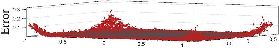
Error distribution of flat surface.
The raw depth images taken by the TOF camera are inaccurate, especially at the edges of the images. According to the error distribution and the periodic characteristics of error variation, the spatial error model of TOF camera is constructed as follows 10


where d is the pixel measured distance, m is the depth value of the center pixel, c
0 is a constant, c
1 is the scale factor,

where E is the loss function of the distance, N is the number of pixels, and the parameter estimation can be done by minimizing the loss function E.
Depth correction
There are some contributions available for depth map denoising and resolution improvement, 27,28 but they often perform not well for this newly developed device. 29,30 In this article, we report an optimization method to improve the accuracy of the depth map. Figure 6 shows the most basic multi-TOF camera system. The depth image with error captured by the mid camera can be corrected by the multicamera system. The specific implementation process is given in Table 1.

Multi-TOF camera correction system. TOF: time-of-flight.
Parameters of error model.

As is shown in Figure 6, A, B, and C are three different points on the object surface. A
1, A
2, and A
3 are the projection pixels of A in the mid, left, and right camera views, respectively.

where
In the error correction experiment, the proposed method faces two situations: (1) the correction point can be captured by the TOF cameras in three views and (2) the correction point can be captured by the mid camera and the camera in one side view, however, the camera on the other side view cannot capture the point.
In the first case, we take point A as an example, which can be captured by cameras in three views. Firstly, we calibrate three cameras in pairs.
31
Based on the transform matrix calculated from calibration, the corresponding pixels of point A on left and right camera projection plane can be determined, which are

where
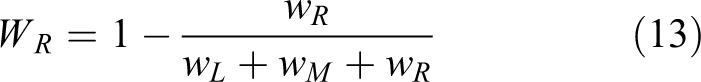
Secondly, we calculate the correction weights of the left camera and right camera according to their error models

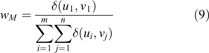
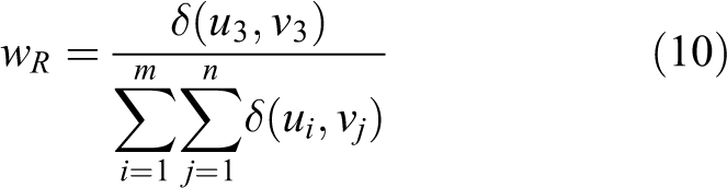
where


where
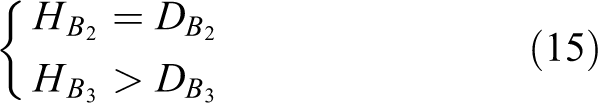
In the second case, we take point B as an example. In this case, point B is shielded by point A in the view of the right camera. We compare the hypothetical depths to the measured depths in the corresponding camera view. If the hypothetical depth is bigger than the measured depth, we set the depth of this point in the corresponding camera view equals to zero, otherwise, we reserve the measurement depth. For point B

where
Experiments and results
Experiment settings
Our experiments are carried out on two types of scenes. The first one is a flat and untextured wall surface (Figure 3(a)), which focuses on determining the spatial error model and verifying the performance of the correction algorithm on a flat surface. The second scene is a spherical surface, which focuses on verifying the performance of the correction algorithm on free-form surface (Figure 3(b)). The measurement results of the TOF camera are influenced by internal temperature. To achieve distance measurement stability, the SR-4000 cameras are warmed up for 40 min according to the test in the previous work. 10
In the first experiment scene, TOF camera is set at 1.5 m from the flat surface based on the standard working range of SR-4000 (0.3–5 m). To ensure the accuracy of the error model, the position of the TOF camera is precisely determined by a longitudinal hammer and a laser rangefinder, and the camera optical axis is perpendicular to the flat surface. In the experiment, the acquisition frequency of the TOF camera is 30 Hz. Five frames of data are collected for each measurement, and the average value is taken to ensure the stability of the data. According to the error model calculation method proposed in the section “Representation of error model,” error model parameters obtained by the least square method are presented in Table 1. Figure 7 shows the fitting surface of the error model which is in blue, and the purple points are the depth error distribution of the flat surface.

Error distribution and the fitting plane.
In the second experiment scene, the radius of the sphere is 0.1 m, and TOF camera is set at 1.5 m from the center of the sphere, therefore, the depth correction method can be performed with the error model calculated from the first scene directly. To avoid mutual interference between multiple TOF cameras, 32 the depth acquisition frequency of three cameras is set as 29, 30, and 31 Hz, respectively. In the experiment, the centers of three cameras are on a straight line, spaced 0.5 m apart. Moreover, the point cloud directly acquired by the TOF camera contains jump edge points, and we use line-of-sight method 8 to eliminate them before the depth error correction.
Results
According to the experiment set in the previous section, the first experiment scene obtains the following results. Figure 8 shows the comparison of depth errors of the flat surface before and after correction, where the abscissa is the number of pixels in the TOF image. The resolution of SR-4000 is

Comparison of depth errors of flat surface before and after correction.
Depth correction experiment on flat surface by different methods.

DOEC: distance overestimation error correction.
Depth correction experiment on sphere surface by different methods.

DOEC: distance overestimation error correction.

Error distribution of flat surface in X–Y view. (a) Raw TOF data and (b) distribution after correction. TOF: time-of-flight.

Sphere surface depth error distribution in X–Z view.

Point cloud distribution of sphere surface. (a) Raw TOF data and (b) distribution after correction. TOF: time-of-flight.
We compare our spatial correction method to the calibration method in the literature 33 (green line in Figure 12) and the distance overestimation error correction method in the literature 34 (purple line in Figure 12). We perform the experiments using the flat surface and sphere surface raw point cloud. As is shown in Figure 12, our method is more efficient than the others. The average error and noise rate contrasts are displayed in Tables 2 and 3.
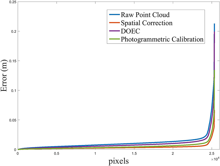
Error correction by different methods.
Discussion
In this article, we propose a spatial error model of the TOF camera and implement error correction based on this model. In the process of first scene experiment, we construct the error model at 1.5 m.

Error correction at different distances with specific error model: (a) 0.5 m, (b) 1.5 m, and (c) 2.5 m.

Error correction at different distances with the error model (

Scope of model application varies with error model construction position.
Conclusion
It is very important to correct these incorrect or inaccurate points before 3D registration and fusion for depth data from TOF cameras. In this article, a novel method to correct error points is presented. The experimental results show that the proposed method exhibits a satisfactory performance using the spatial model for error correction. The corrected point cloud of the target object is more approaching the true value although it is not perfectly matched. In the future, we will perform some tests to further optimize the error model, thus improving the correction weights to obtain a higher compatibility with the ground truth.
Footnotes
Declaration of conflicting interests
The author(s) declared no potential conflicts of interest with respect to the research, authorship, and/or publication of this article.
Funding
The author(s) disclosed receipt of the following financial support for the research, authorship, and/or publication of this article: This work was supported by the National Key R&D Program of China [2018YFB1305200] and the National Natural Science Foundation of China [U1509207].