
Abstract
Walking is considered to be a rather complicated task for autonomous robots. Sustaining dynamic stability, adopting different gaits, and calculating correct foot placement are a necessity to overcome irregular terrain, various environments and completing a range of assignments. Besides that, certain assignments require that robots have to walk on fragile surfaces without damaging it. Furthermore, under some other circumstances, if walking is careless, robots could suffer damage caused by the impact of the terrain. Foot placement, leg motion speed must be controlled to avoid braking surface or even sensors on robot’s feet. In this article, a simple leg placement algorithm is proposed that controls hexapod robot’s leg speed. Thus, force dependence on leg motion speed and step height has been measured by using a piezoelectric sensor. Then, by using leg placement algorithm, we show that the reduction of the impact force between robot’s foot and surface is possible. Using this algorithm, robot feet’s impact force with the surface can be minimized to almost 0 N.
Introduction
For many years, walking machines have been used to perform various experiments to test robotic abilities in different types of walking, overcoming various terrain features (roughness and stiffness), executing a set of operations, and even disabled movement. 1 The reason for developing walking robots is their ability to overcome irregular terrain and adapt to almost any kind of environment. Despite the fact that a great number of the investigated methods as well as the majority of the problems have been already solved with the assistance of the detailed testing and their afterward implementation, several new problems remain. Most of these problems are related to walking instability, 2 foot positioning inaccuracies, foot-ground contact, 3 movement speed control, 4 and energy consumption. 5 –7 In any case, robot contact with different types of surfaces or object manipulation is a very important factor in sustaining robots functionality. Robot contact with the surface can be used to maintain many walking and grasping parameters such as stability or dynamically balanced gait computation, 8 energy consumption, correct foot/hand positioning, movement trajectory generation, and terrain stiffness evaluation. This indicates the necessity of force/torque sensors in robotic systems. The following section discusses force control methods used for robots.
In the object manipulation field, force sensing is important in order to control correctly the process of grasping. In case an object is pressed too hard, it might break. The experiment was conducted with seven degrees of freedom (DOFs) Robotics Research arm 9 in 1996. In this experiment, the forces and torques were measured on the wrist using a six-axis force/torque sensor. The importance of the research was motivated by the possibility to control the impact forces between the robotic manipulator and two types of surfaces: hard surface and soft surface. Three different methods for contact control were tested: compliance control, force control, and dual-mode control. The results indicated that by applying the force/torque sensor and simple control algorithms it was possible to interact with hard and soft surfaces and reduce the impact force between the robotic hand and the surface.
Subsequently, the force control was introduced into the walking robots such as quadruped, hexapedal, and bipedal (humanoid) robots. Scholar Song and Lin proposed and introduced in his work in 1997 the way, how the force/position control 10 could be solved. He applied cerebellar model articulation controller (CMAC) for a quadruped walking machine. The accuracy improvements were demonstrated and related to the control by the dynamics approximation of a single leg. However, the results were achieved by series of modeling and simulations, without the use of any real robots or without any actual force sensors to prove the quality of CMAC algorithm.
Thus, one of the major reasons for the walking robots to be used is their possibility of adaptability to the irregular terrain surfaces. Force sensors can be used to sustain dynamic stability when walking on extreme terrain. Also, by using force feedback, it is possible to evaluate the contact with the surface and use this information to recalculate leg trajectory if necessary. 11 Furthermore, the change in center of mass and body attitude has been taken into account 12 along with the foothold selection. 13
In certain cases, a force sensor (or sensors) can be used instead of the accelerometers or gyroscopes to sustain walking stability. Such example is a humanoid robot KHR-2. 14,15 The proposed algorithm has incorporated only force/torque sensors to execute dynamic stair climbing and walking ready posture.
Dynamic balance and stability are also important to quadruped and hexapod robots even though they have a higher number of legs to support the body. Using force/torque sensors, it is possible to achieve a better walking stability or compensate external perturbations demonstrated in the four-legged robot LittleCrabster by Kim. 16 Three-axis force/torque sensors were mounted on hip joints to obtain force feedback in order to evaluate external forces and to eliminate possible perturbations. A similar experiment was performed with the hexapod robot by Agheli and Nestinger. 17 The difference from LittleCrabster was that force sensors were positioned on the bottom of hexapod robots feet. The methods used indicate the possibility to avoid tipping over when the external forces are applied from any direction.
Speed is also an important factor for walking robots as they tend to be much slower than wheeled and tracked machines such as cars and tanks. Reaching higher walking/running speed is considered a very complex task. To accomplish such a task, the measuring of the joint orientation during the support phase is required. 18 Nevertheless, the joint orientation alone is not enough. That is why a fuzzy rule set has been applied to coordinate automatically the acceleration of the legs. The method proved to be a rather innovative improvement in walking locomotion and thus has increased the robotic speed.
Many scientists tend to use the biological aspects as the inspiration for constructing the robotic systems and for developing the new methods of control. Force sensing is found in almost all animals and insects. The biologists, who observe live organisms in nature, suggest that cockroaches are able to sense the force by means of the sensors located on the legs close to their bodies and to use the received information to correct the motion. 19 According to these observations, the insects tend to use force feedback to be able to adapt to the irregular terrain surfaces, which appear to be the main advantage of walking. The similar bio-inspired examples were presented by Spenko et al., 20 Bartsch et al., 21 and Haynes et al. 22 Using hexapod robots with integrated force sensors on each foot (along with other sensors), special algorithms were designed for both horizontal walking and diverse surface wall climbing. However, by adding the multiple sensors, the control of the whole system becomes complicated 23 and requires to compose more complex control methods. The tactile force sensors are used to classify different types of terrains, 24 such as wood, sand, rocks, and so on. By measuring the changes of force and torque over a certain period of time, walking parameters and terrain classifications have been obtained. This information was later used to develop a special movement controller to move more efficiently on various surfaces. By series of testing, enough results were gathered to prove that this method can improve walking locomotion.
The importance of the research
As mentioned in the previous section, most of the issues in walking robots concern static and dynamic stability, overcoming irregular terrain or adapting to various environments, foot positioning, walking speed, movement trajectory computation, path planning, and energy consumption. Over past 50 years, many different experiments were performed to test the validity of different methods in order to solve problems and to make walking locomotion superior to wheeled or tracked locomotion.
However, none of the previously mentioned work was related to structural damage to the surface that robot is walking on or damage to the robot or its sensors. The topic could be considered valid for cases of walking in terms of hard irregular terrain surfaces (rocks, concrete, metal surface, etc.) or in cases of very soft/fragile terrain surfaces (glass, thin wood, rusty metal, carton, etc.). Besides that, the sudden movement or fast leg transfer might cause damage to the legs/sensors of the robot or break the surface. These occurrences are highly dangerous both to a robot itself and to the surrounding environment (or humans/animals if they appear to be located nearby) when performing the task.
Although many different force control methods have already been proposed as discussed in “Introduction” section, most of them are very complex and require various sensors to work. This might result in additional problems as installing several sensors on one leg which is not an easy task and difficult algorithms might require high computational power.
In this article, we present a simple algorithm for minimizing the impact force between the leg of the robot and the surface by using only a single sensor on one leg. First, the voltage dependence on step height and leg speed is measured using piezoelectric force sensor. Then, by means of the piezoelectric characteristics, the voltage dependencies are recalculated into force dependencies for both parameters. Finally, the leg placement method is developed to control leg movement speed. The method is implemented into the control system of the hexapod robot and experimentally tested to prove the validity.
Hexapod robot description
In this research, experiments were carried out using the real hexapod robot model (Figure 1). This is a fourth hexapod model, with more advanced control system and mechanical components. All tibia parts were printed using 3-D printer; robot’s body was developed for better static and dynamic stability and was cut from 3-mm-thick plastic using laser CNC.

Hexapod robot.
For control system, STM32F411RE Nucleo board has been used with additional 5 V (7805 type) voltage regulator for microcontroller, while servomotors use 10 V (a single power supply source has been used). Additionally, 74HC126 and 74HC04 circuits for data conversion have been added to switch between Rx and Tx channels for Dynamixel AX-12 servomotors. The diagram of the control system for the hexapod robot is presented in Figure 2.

Hexapod robot control system diagram.
The mass of the robot is approximately 1.5 kg. The dimensions of the legs are as follows: coxa 50 mm, femur 82 mm, and tibia 120 mm. The length of the hexapod is 250 mm, width in the middle is 190 mm, and width at front and end is 100 mm.
The hexapod robot consists of 18 AX-12 servomotors that provide 18-DOFwhich makes it possible to change the movement parameters such as gaits (tripod, tetrapod, ripple, and wave), step height, movement speed and direction, single servo speed, step length, body elevation, body rotation, and body translation.
Upgrading robot leg
The piezoelectric sensor has been used to measure the impact force between the hexapod robot leg and the surface. Although the piezoelectric sensors are mostly used for the dynamic forces to be observed, in our case, it has been very useful when observing and recording the exact moment when the foot touches the ground. The piezoelectric sensors are rather small and therefore, they fit precisely for the legs of the robot as they do not require complex additional equipment (only comparator or Analog-to-digital converter (ADC), and oscilloscope for initial measurements); they are fairly cheap; they have high-temperature resistance and are insensitive to the external electric and magnetic fields, which makes it easier to obtain valid information.
During all the experiments, only one hexapod robot leg has been used. To attach piezoelectric sensor at the bottom of the foot, we have added a metal bolt and connected it to the leg. Besides that, in order to have a better contact between the foot and surface, we have provided a small plastic part at the bottom side of the sensor. Finally, both the positive and negative sensor connectors were wired directly to oscilloscope. The upgraded hexapod robot leg is presented in Figure 3(a).

Experimental setup for measuring voltage dependence on impact force. (a) Robot leg with piezoelectric sensor and (b) voltage measuring diagram. Positive and negative connectors are connected directly to oscilloscope.
Initial experiments
First, to observe the way the force changes in accordance with the step height and leg speed, the voltage has been measured, because the piezoelectric sensor tends to produce the electric charge under the deformation. Thus, a very simple experimental setup has been designed (Figure 3(b)). The piezoelectric sensor has been attached to the hexapod robot leg and connected to the oscilloscope.
Proper evaluation of force dependence on step height and leg speed requires to measure voltage for both cases separately. This way it is easier to see which of the parameters has a stronger influence on force. For each separate measurement, the step height or leg speed has been set to a constant value, and only one of these parameters has been changed. Leg movement speed is changed by increasing or decreasing the number of points in the leg trajectory. Fewer points in trajectory result in higher leg speeds and vice versa. The number of points in trajectory is determined by changing time steps between the points. By increasing the time steps, the number of points in trajectory is decreased; thus, the leg movement speed is increased. The individual servo speed is calculated automatically according to the leg trajectory and inverse kinematics. Direct leg speed in z coordinate can be calculated using the following equation

where vz is the leg speed between two closest points, h is the step height, and res is the time step. The numerator of equation (1) calculates the distance between two trajectory points, while the denominator of equation calculates the time needed for the leg to travel the given distance.
All the experiments have been carried out using step height between 5 mm and 75 mm. However, only less than half of the maximum time step (the constraint time step is 25) has been applied due to the appearance of the jerky movements.
Each measurement has lasted approximately for 12 s. During this time, the robot has constantly raised its leg and then positioned it back on the surface. By doing so, we managed to obtain an ample amount of impact forces for each configuration and the voltage value has been calculated by averaging all positive peak values as presented in Figure 4 and the following and equation

Sample measurement. Step height is 6 cm; time step set to 6. Circles represent foot contact with surface.

where U avg is an average voltage, U1, U2,…, Un is the voltage peak values, and n is the number of peaks.
Averaging has made sure that the correct voltage value has been obtained for that particular leg configuration (leg speed or step height). It is not enough to have only one force measurement, because piezoelectric sensor is very dynamic and the impact time is very short; therefore, force peak value is not correct sometimes (it is lower or higher). Thus, it is possible to calculate the deviations, which simplify the approximation of the obtained results.
The reason for averaging only the positive values is because of the piezoelectric sensors which are bidirectional. Besides that, when pressing the sensor, it is possible to attain the positive electric charge and when releasing the pressure, the negative electric charge is obtained; after the deformation, the electric charge tends to drop to the zero point. In this case, the positive voltage represents the foot impact with the surface, but the negative voltage indicates the moment when the robot raises its leg. Experimental results are presented in Table 1 and Figure 5.
Hexapod robot voltage dependence on step height. Time step set to a constant values.


Voltage dependence on (a) robot step height and (b) time step. Measurement data presented as dots; exponential approximation given as line.
Piezoelectric sensor characteristics
In order to evaluate foot impact force correctly, voltage dependencies have to be recalculated into force. To achieve this goal, a stand has been designed to measure piezoelectric sensor characteristics (Figure 6). This stand has been designed to closely resemble the way robot places its feet on the ground. By doing so, we have ensured that the characteristics could be appropriately obtained and could be useful for our research.

Piezoelectric sensor characteristics measuring stand.
The stand has been composed of the piezoelectric sensor firmly attached to the solid surface and connected to the oscilloscope. Plastic tubes of diverse heights have been placed on the top of the sensor correspondingly bearing the following heights: 50, 100, 150, and 200 mm.
To imitate the robot leg placement on the surface, a small metal ball of mass m has been thrown down the tube. The plastic tube has ensured the metal ball to be continuously hitting the sensitive area of the piezoelectric sensor, thus allowing the recording of the correct raw data. The oscilloscope has been calibrated to save only a single impulse which has simplified the acquisition of the data and has presented more accurate recordings. Each metal ball has been thrown at least 5–10 times through the same tube and the average voltage has been calculated.
Force at which metal body hits the piezoelectric sensor can be calculated using the following equation

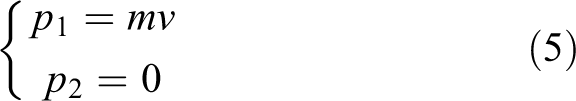
where Δt expresses time of impact or impulse duration, and Δp is the difference between momentum at the highest point p1 and the moment of impact p2

It is known that the potential energy has a maximum value at the highest point, while at the moment of impact, potential energy translates into force. Thus, we have that p1 and p2 values as follows
where m is the metal body mass, v is the body speed at the lowest point which can be expressed by

By applying equations (4) and (6), we find Δp

By inserting equation (7) into equation (3), we get final solution for calculating force

As it has been mentioned before, Δt expresses the duration of the impulse which has been derived from the experiments. In this case, the value of the impulse duration is equal to Δt ≈ 20 ms. After all the experiments have been performed, the required data have been collected for each body mass to be recalculated into force by using equation (7). The obtained results have made it possible to determine the force dependence on the voltage (Figure 7). The final equation regarding the force dependence on the voltage is presented in equation (9). The equation has been applied in all the subsequent experiments

Piezoelectric force sensor characteristics: force dependence on voltage. Black dots mark measured data; red line represents exponential approximation.

Force dependence on step height and leg speed
In order to recalculate the measured voltage dependencies into force dependencies, the piezoelectric sensor characteristics have to be applied. The result regarding the derived force dependence on voltage is presented in equation (9). Force dependence on step height and time step is presented in Figure 8.
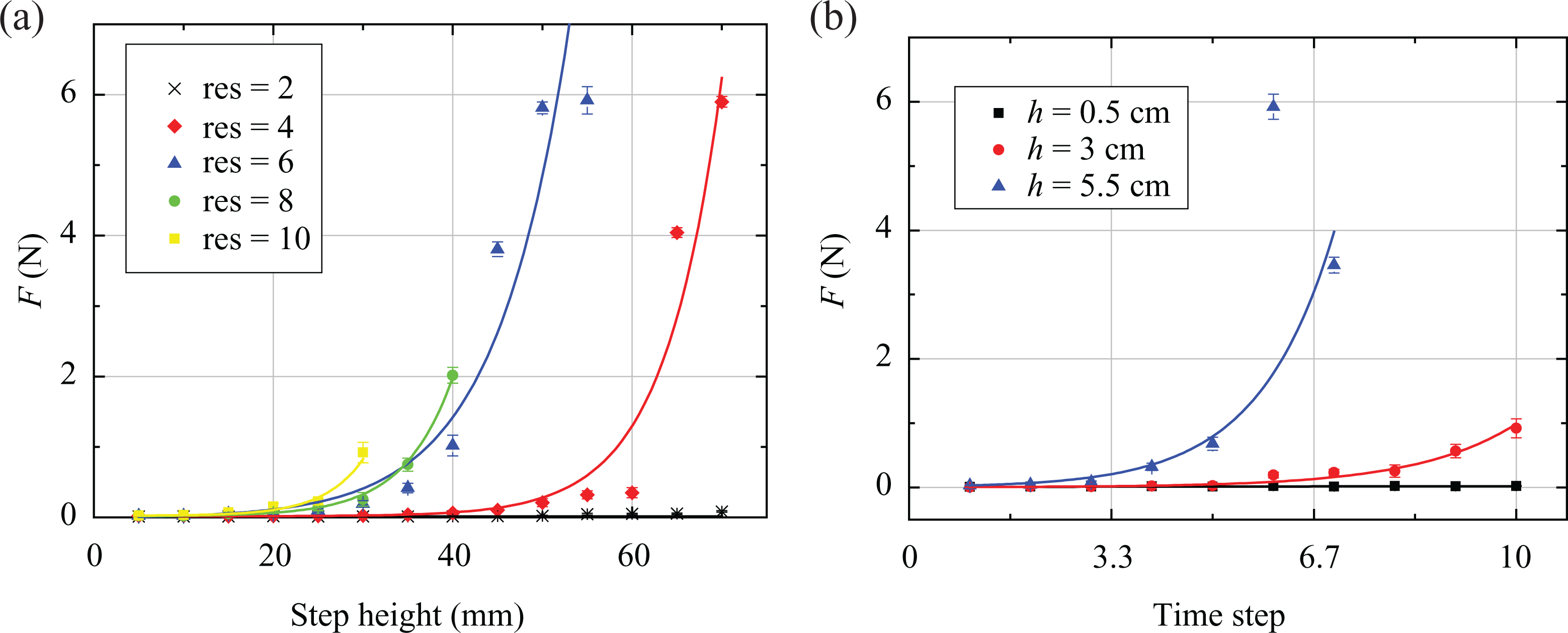
Force between robot foot and surface dependence on (a) step height and (b) time step. Measurement data presented as dots; exponential approximation given as line.
Figure 8 indicates that both the step height and leg speed provide a rather strong influence on the force. The derived curves have exhibited the exponential growth which could be observed when the force starts to rise at lower speeds while the step heights with one of them remain constant (e.g. the force is much higher at higher leg speed for the same step height and vice versa). During the experiments, impact force between robot foot and surface reached 6 N. Only when the step height is set to 5 mm the impact force remains at approximately 0 N (Figure 8(b)) and does not depend on the leg speed. The recorded dependencies (Figure 8) indicate that by increasing the step height or leg speed, a greater damage could be caused to the robot itself and/or the surface it is walking on. Therefore, in order to prevent the damage, the range of the walking parameters has to be limited. In our case, the step height has to be limited to a maximum of 20 mm (Figure 8(a)), and the time step has to be limited to approximately 3–4 (Figure 8(b)). By doing so, this robot’s walking capabilities (walking speed, obstacle clearance, etc.) would be limited as well.
Leg placement algorithm and preliminary testing
The theoretical understanding of the problem appears from the fact that the impact force between the object and the surface is dependent on the object movement speed; the following equation proves the statement

where m is the mass of the object, v is the object movement velocity, and timp is the duration of the impact. The same equation applies when the robot moves its leg up and down.
Equation (10) has indicated that there has not been any direct force dependence on the step height. However, the following dependence could be derived from the foot coordinates of the robot. The leg movement up and down of the hexapod robot is controlled by the following equations


where h is the step height, t is time, and φi is the leg phase. By differentiating equation (13), it is possible to derive the following equation on the robot leg velocity
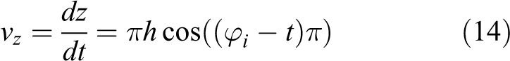
Accordingly, the leg velocity is proportional to the step height, but the dependence is not linear. Therefore, by increasing the robot step height, the leg speed is increased as well as the impact force is increased.
By looking at equations (10) and (14), we can see which of the parameters influence impact force. In our case, however, not all parameters can be controlled. In other words, even though mass m has a significant influence on the impact force, the mass of the robot remains constant due to its permanent structure. The impact time timp has not been controlled as well, because it is mostly dependent on the conditions and circumstances of the experiment (surface type). We consider timp to be a constant value. That is why only two actually controlled parameters remain, namely step height h and speed vz which is also dependent on the step height. This explains why having greater h value with small vz value gives small impact force while having small h value with large vz produces large impact force (Table 1). In any case, out of remaining two controllable parameters, speed is more influential than step height because step height only changes leg speed indirectly.
To reduce force dependence on the step height and leg speed, a simple leg placement algorithm has been developed (Figure 9). Since speed is more important than step height as has been mentioned above, we choose to control leg movement speed. The algorithm has been implemented directly into hexapod robot control program.

Leg placement algorithm for controlling the leg movement speed.
The leg placement algorithm controls only the speed of the hexapod robot leg by changing the time step value (see “Initial experiments” section). The input parameters for force dependence on the step height: step height h = 10 mm, step length l = 0 (robot leg only moves up and down), and time step res set to constant value. Afterward, the step height has been changed to h = 20 mm, and experiments have been repeated including all possible step heights. The input parameters for force dependence on the leg speed: step height h set to constant value, step length l = 0, and time step set to minimum res = 1. Afterward, the time step has been changed to res = 2, and experiments have been repeated with all the available time step values. The output of the algorithm is foot z coordinate that has been calculated from the leg trajectory (equation (13)). The finiteness of the algorithm is defined by the number of the steps the robot has to cover. As it has been mentioned in “Initial experiments” section, at least 12 s of data have been required and that is why a larger number of steps have been included depending on the input parameters. Although, this algorithm contains no feedback to determine the proximity of the surface, which means that the z coordinate of the robot leg is only controlled by inverse kinematics and a human operator. This algorithm would not work on irregular terrain. The leg placement algorithm operates in the following way, the movement is initiated as an ordinary one and does not depend on the gaits, then the phase of leg lifting commences (during this phase nothing is changed); during the leg lowering phase, the robot checks the position of the legs descending toward the surface and in case the phase of lowering is canceled and in case the surface is approached, the leg speed is switched off, then both the phase and the algorithm are repeated.
To evaluate the most suitable step height and time step for the algorithm, several preliminary experiments have been carried out. The settings and adjustments of the tests are presented in Table 2. Three different settings have been applied for these tests. The step height and time step have been fixed to the constant values of 55 mm and 7 and the changes have been made only regarding the reduction of the height of the leg movement. When surface is near, time step was set to almost minimum value possible – 1. For step height, we used 5, 10, and 20 mm for slowing the leg movement, because the hypothesis for these experiments was that the earlier the leg is slowed down, the lower the impact force will be. However, the preliminary tests have provided the opposite results compared to the previously made assumption. The experiments proved that the best height for slowing the leg movement related to the proposed leg placement algorithm is considered to be at 5 mm.
Settings for preliminary testing.

Results and discussion
To verify that the proposed algorithm operates sufficiently and could be used to reduce leg impact forces, some additional experiments have been carried out. Leg placement algorithm has been implemented directly into hexapod robot control program only using the most optimum parameters.
Experimental setup has been the same as presented in Figure 3(b). In this case, only the force dependence on the step height has been measured. The time step has been set to 5. For this measurement, the minimum step height has been set to 20 mm. Force dependence on step height results is presented in Table 3 and Figure 10. In Figure 10, the additional curve from the first experiment has been added to reflect more extensively the difference between the dependencies with and without the leg placement algorithm. The step height and time step for the curve have been chosen to be as close to the measurements of the algorithm as possible.
Force dependence on the step height using leg placement algorithm.


Force dependence on the step height using algorithm (red line) and without the algorithm (black line).
The leg placement algorithm reduces the impact force between hexapod robot’s foot and surface almost to zero. Average impact force equals to approximately 0.0082 ± 0.0007 N, whereas without algorithm impact force reaches 6 N for our hexapod robot. By using this algorithm, it is possible to obtain up to 99.86% of force reduction where 100% reduction would mean that robot is not touching any surface (physically it is impossible).
However, it should be noted that leg placement algorithm is still under development and would not work in all cases. We only conducted experiments on flat surface which means that algorithm might still fail on uneven terrain. Some additional sensors on the legs of the robot are required (such as the infrared sensors) to measure the distance of the foot to the surface. The leg placement algorithm has been tested by using only a single leg of the robot. By implementing the algorithm for each leg of the robot, it could be possible to obtain certain valuable information on how the movement speed, stability, and gaits of the robot are affected by the leg placement algorithm as well as energy consumption. Finally, by using different types of surfaces (mud, grass, sand, etc.), some interesting results could be obtained.
Despite high impact force reduction with the leg placement algorithm, it is difficult to compare obtained results with the other methods, because few insignificant efforts have been made to minimize the impact force between the foot and the surface. The research on the subject quoted in Zhao et al. 25 indicates that the impact force between the swinging legs and the surface has been reduced from ∼17–17.5 N to ∼15–16 N by using the errors of the swinging legs of the robot; 1.5−2 N is a very insignificant difference, and the algorithm requires more precise improvement. Another research presented by Shourijeh and McPhee 26 shows that in some cases foot contact forces can reach up to ∼100 N which implies the need for force reduction algorithms. Authors have presented a method using which it is possible to obtain 62%–75% force reduction during impact. Although this method has shown some quality results, all experiments have been carried out in simulation program and our proposed leg placement algorithm is still more efficient. Yamada et al. 27 presented the way the spring has been applied on the foot in order to reduce the impact force. With the help of the spring, a more gentle response has been obtained, but nothing has been mentioned in terms of the force minimization. In other studies, such as the works of Kim et al. 14 and Lee et al., 28 the force/torque sensors have been used and foot contact forces measured; they have mostly been applied for controlling the stability of the humanoid robots. The information on the foot-surface impact forces has not been mentioned.
Conclusions and future work
In this article, the hexapod robot impact forces between foot and surface dependence on step height and leg speed has been observed. The piezoelectric sensor attached to robot’s foot has been used to measure voltage that is proportional to impact force. The voltage has been recalculated into force using piezoelectric characteristic measurements. Thus, the leg placement algorithm has been derived, tested, and implemented into the control system of the hexapod robot in order to reduce the effect of the impact forces. The validity of the algorithm has been determined by providing the additional experiments.
The obtained force dependencies on the step height and leg speed have proved and validated the exponential growth. With 55-mm step height and 6 time step, it is possible to reach up to 6 N impact forces when robot’s foot touches the surface. Experimental results provide information about forces that are high enough for robot to damage sensors that are fixed on the feet: while observing voltage dependence on the step height and leg speed, one piezoelectric sensor has been broken on the robots foot (contacts have been broken and sensor has no longer been useful). These situations have indicated the necessity for developing our leg placement algorithm which has been used to control leg speed during the leg motion toward the surface.
The preliminary testing related to the proposed algorithm has indicated that the most suitable height to change the leg speed is at 5 mm. The time step at that moment has to be set to 1. The additional experiments have proved that with the help of the leg placement algorithm, it is possible to reduce the impact force almost to zero. The force has dropped from 6 N down to ∼0.0082 ± 0.0007 N. The efficiency of the developed algorithm for the hexapod robot is 99.86%. We have only tested this algorithm on specific hexapod so the efficiency might change for a different type of robot or any other walking machines.
Nevertheless, the derived algorithm has not completely been finalized and further and more specified investigations are required. As mentioned in “Leg placement algorithm and preliminary testing” section, the leg placement algorithm would not work on irregular terrain as robot has no foot placement feedback and will not detect proximity to the surface. Further improvements to the algorithm are required. By installing the additional sensors to measure the distance between the feet of the robot and the surface could significantly assist the performance and would not require the step height and leg speeds to be hardcoded. Another possibility to control the feet placement speed is to derive the speed control polynomial in order to interpolate the leg movement speed during the whole stride and especially to decrease the speed before the feet placement.
Besides that, the speed of the motion of the robot is changed, when controlling the leg speed. In case the leg speed is reduced during each step, the walking speed might decrease drastically causing the increase in the energy consumption. Conducting experiments to understand the speed difference with and without algorithm would suggest the possible solutions for our leg placement algorithm.
To measure the voltage dependencies, we have used the piezoelectric sensor. They could be used only for measuring the dynamic forces. Using a different type of force sensors (barometric force sensors, force/torque sensors, etc.) would allow measuring static forces and improve precision. The investigation of the static forces could provide additional information on the contact between the feet and the surface during the leg placement motion as well as force dependence on various terrains or on the stiffness of the terrain.
Finally, measuring mechanical deformation and structural damage of the surface that robot is walking on would be important to see on what types of terrain walking robots can perform movement without any additional leg speed control and on what terrains our leg placement algorithm could be useful. This information could later be used to perform real-life testing to evaluate our hexapod robot’s ability to carry out operations in fragile environments.
Footnotes
Declaration of conflicting interests
The authors declared no potential conflicts of interest with respect to the research, authorship, and/or publication of this article.
Funding
The authors received no financial support for the research, authorship, and/or publication of this article.