
Abstract
In this paper the kinematic analysis of a six-legged robot, hereafter named Hex-piderix, is carried out. A three revolute (3R) chain has been chosen for each limb in order to mimic the leg structure of an insect. The rotation matrix, with unitary vectors, and the Denavit-Hartenberg (D-H) conventions are used to find the pose of the thorax. The problem of inverse position is solved by geometrical analysis. The direct and inverse infinitesimal kinematics are obtained by the reciprocal screw theory, considering a suction cup attached to each leg and modelling it as a UP linkage. A numerical example of the thorax pose was made by solving the equations obtained from the direct position analysis. The equations of the inverse position analysis were solved to obtain the angles of the joints. Finally, the velocity values of the thorax obtained from the infinitesimal kinematics were validated by simulating the movements of Hex-piderix using specialized software.
1. Introduction
Legged robots have better performance in rough terrain than robots with wheels, thanks to the possibility of coordinated movements that provide greater flexibility and adaptability.
Legged robots can be classified as: bipeds, quadrupeds, hexapods and octopods. Most climbing robots are hexapods or quadrupeds - the former providing better static stability than the latter. They can perform static gaits by supporting the robot's body on five legs at any time, while quadrupeds can only walk steadily on a minimum of three legs. This feature makes hexapods much more stable than quadrupeds, since they can use a bigger support polygon. Notice that stability is a fundamental issue for mobile robots and speed is an important factor for robot locomotion - a quadruped robot is three times slower than a hexapod. In terms of reliability, the hexapod can continue walking even when one of its legs fails [1].
To obtain a dynamic model and to design a control algorithm of legged robots, it is important to model the kinematic behaviour of the complex multi-legged robotic mechanism.
In [2], the inverse position problem for each end-effector (EE) of the legs of the quadruped robot CLIBO is solved by homogeneous transformation matrices. The same approach is presented in [3] for a hexapod robot assuming forward motion at a constant velocity (v) in a straight path on a flat surface with alternating tripod gait. In this case, the thorax is held at a constant height and kept parallel to the ground plane during motion, and the thorax gravity centre is assumed to be located at its geometric centre. In [4], the problem of a hexapod robot is solved as in [3] but without any restriction.
A legged robot can be considered a partially parallel mechanism where the thorax is the mobile platform. In [5], the direct and inverse kinematics of the mobile platform of the quadruped robot Kamambaré, are solved by modelling it as a parallel robot. The analysis is performed using the D-H parameterization, starting at the surface and advancing towards the platform.
The work presented in [6] solves the kinematics of a four-legged robot composed by GZ-I modules, using kinematics graph theory to obtain robot posture. Two homogeneous transformation matrices describe the position of the robot, matrix R of rods and matrix J of joints. The joints are classified into horizontal and vertical joints depending on their axis of rotation.
The position problem of the tip leg has been studied for quadruped and hexapod robots [2–6], however, the problem of the thorax pose has received little attention [5–6]. Furthermore, the infinitesimal kinematics of legged robots have been omitted.
One of the most important things in the study of legged robots is showing stability when walking. [7] conducted a study of impulse response and stability of a fractional oscillator, which determine the conditions for the fractional oscillator is strictly stable, unstable and marginally stable. Which determine the conditions to make it strictly stable, unstable and marginally stable.
In this paper, an analysis of the direct and inverse position of the hexapod robot called Hex-piderix is carried out, in addition, the infinitesimal kinematics are solved by using screw theory.
2. Description of the Hex-piderix robot
The basic configuration proposed for the robot Hex-piderix is shown in Fig. 1. The frame {0} represents the origin, while {Q} indicates the local frame attached to the robot thorax. The robot consists of six identical legs, L1, …, L6, that are distributed symmetrically around the thorax of the robot. Each limb has 3 degrees of freedom (DOF) that consist of three links, coxa, femur and tibia, connected by rotational joints. In the tip of the tibia there is a suction cup to adhere to vertical surfaces.

Robot configuration.
3. Position analysis
The symmetry of the mechanism simplifies the position analysis. The inverse and direct kinematics are solved from geometrical analysis of the mechanism.
3.1 Forward position analysis
The aim of this analysis is to find the robot pose at the thorax level {Q} with respect to {0} for a given set of joint angles, qi,j, where i represents the number of the limb (i = 1,…. 6) and j the number of the joint (j = 1, 2,3).
To determine the pose of the robot it is assumed that there are three legs touching the ground, L1, L3 and L5. The corresponding coxa links, represented by the points P1, P3, and P5, form an isosceles triangle composed by base a and sides b. The local frame {Q} is located at the triangle's centroid, its axis XQ is directed to P1 [8], as illustrated in Fig. 2.
To ensure the stability of the robot, the projection of the centre of gravity must fall within the polygon formed by the tips of the limbs.

Triangle formed by coxa links.
The unitary vectors corresponding to {Q} were calculated as follows:


where,
The rotation matrix of the centroid is obtained with the unitary vectors, Eq. (4).

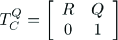
Then, the pose of the triangle is described by the homogeneous transformation matrix 4 × 4 TQC defined in Eq. (5):
The rest of the analysis is performed with the D-H method for a leg. In Fig. 3 the joint variables of the mechanism leg, qi,1 Qi,2, >Qi,3 are defined, as well as the lengths of the coxa, femur and tibia, d1, d2, d3 respectively.

D-H parameters of i-leg.
The limbs described above are similar to 3 DOF serial manipulators. From this, the homogeneous transformation matrices between frames are obtained, taking into account the D-H parameters shown in Table 1, which are: link length (ai), link twist (α i ), joint distance (di) and joint angle (θ i ), required to completely describe the three joints of the legs.
D-H parameters for legs.

The homogeneous transformation matrix that describes the translation and rotation between frames i and i-1 [9], is shown in Eq. (6).

The homogeneous transformation matrices of the links are presented below in Eqs. (7), (8) and (9).

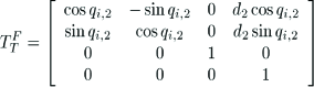

Hence, the pose of the coxa frame {Ci} with respect to {S i }, is defined in Eq. (10).

Then, the frame attach to thorax {Q} is defined, with respect to {S}, in Eq. (11).


where,

where, [rx,rv,rz] corresponds to centroid coordinates, 8j= sin(qi,j) and, Cj=cos(q i,j ).
3.2 Inverse analysis position
This analysis consists of determining the joints angles, qi,1, qi,2 and qi,3, starting from a given pose of the thorax.
The problem is solved for each leg separately, in a geometric way considering three restrictions: 1) all joints permit only rotation about an axis; 2) the femur and tibia always rotate around parallel axes, and 3) the physical constraints of each joint, which give a specific angular range for each active joint.
The coxa angle, Fig. 4, can be found by projecting the i-leg on the plane XY, Eq. (12).
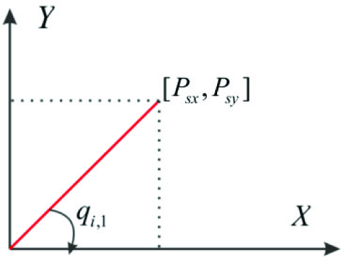
Projection of the i-leg on plane XY.

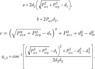
From Fig. 5 and Eq. (12), qi,2 and qi,3 are expressed as:


Configuration of i-leg.
Where,
4. Infinitesimal kinematics
The velocity and acceleration analysis of the robot are solved using screw theory. As an approach to the study of the dynamics of the robot, the manipulator is assumed as a parallel mechanism. Its limbs are modelled as shown in Fig. 6.
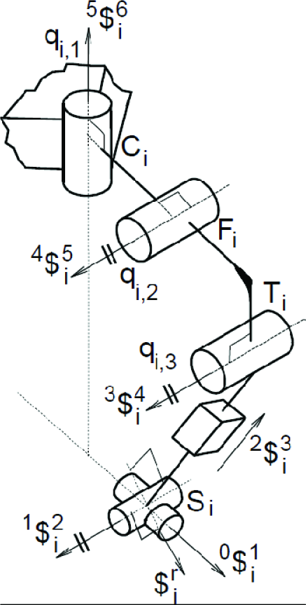
i-th kinematic chain robot.
Note that the active revolute joints are associated with the screws 3$4 i , 4$5 i and 5$6 i . During normal operation of the robot, the motor corresponding to twist 3$6 i , is used to move its limb during the locomotion. When the manipulator is in a stable position, this joint becomes a passive joint; however, since the motor has an encoder, its angular position, velocity and acceleration are known. The motors associated with screws 3$4 i and 4$5 i , orientate the thorax with respect to the global frame.
On the other hand, the suction cup is modelled as a UP linkage, and its corresponding screws are 1$1 i , 1$2 i and 2$3 i whose axes are mutually perpendicular. In practice, the displacements of these screws rely on the elastic properties of the suction cup.
4.1 Preliminary concepts of screw theory
An infinitesimal screw $, or twist, is a vector in $ ∈ ℝ6 that consists of a primal part,

where h is the screw pitch.
Moreover, the following operations are defined [8]. Let $1=(ŝ1,sO1),$2=(ŝ2,sO2),$3=(ŝ3,sO3) be three screws, and λ ∈ ℝ.
Addition:

Multiplying by scalar:

Lie product
Killing form

Klein form

4.2 Velocity analysis
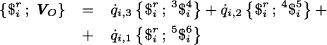
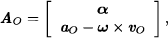
The forward velocity analysis consists of finding the velocity state of the thorax, Vo, with respect to the global reference frame, given the joint rate velocities aωbi. It is given by the following expression:

where ω and vo are, respectively, the angular and linear velocity of the thorax with respect to the global frame. The terms aωbi represent the ratios of rotational or translational velocity of body

where
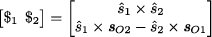
A useful concept to simplify this analysis is reciprocity. Two screws, $1 and $2 are reciprocal if the Klein form between them is zero, {$1; $2} = 0. With this definition, one can demonstrate that the screw 1$2
i
is reciprocal to all screws belonging to the

On the other hand, let $
τ
i
be a zero-pitch screw that passes by point
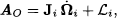
Eqs. (22) and (23) can be written as a lineal system as follows:

where
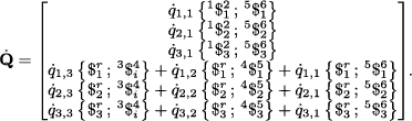
Thus the state of velocity
Moreover, the inverse velocity analysis consists of finding the ratios of manipulator velocities for a given velocity state. To achieve this, it is necessary to isolate Ω i in Eq. (21).
4.3 Acceleration analysis
Brand in 1947 introduced the concept of reduced acceleration state,
where
where

In the same manner as the velocity analysis, the Klein form is applied to Eq. (26) and screws 0$1 i and 2$3 i . This leads to

where,
Finally, to solve the inverse analysis, it is necessary to isolated in Eq. (26).
5. Numerical example
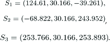
In this section a numerical example is provided with the purpose of showing how to deal with the kinematics of this model. Hereafter the units used are millimetres, unless otherwise stated. In this case, the dimensions of the geometrical parameters of the moving triangular prism are a = 153 and b=131.203, meanwhile Q = (116.803, 216.711,160.772) is the centre of the prism; whereas the nominal positions of the revolute joints connecting the limbs to the first link are:
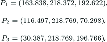
The coordinates of the suction cups are:
Links length, coxa, femur and tibia are given by: d1 = 57.61, d2 = 64.54 and d3 = 11.41, respectively.
Fig. 7 shows the joints angle of the legs L1, L2, and L3, for the time range 0-0.25 seconds.

Position of the joints angle.
Firstly, the direct position equations were programmed to calculate the thorax pose, taking into account the initial and final positions, as well as geometric parameters. Fig. 8 shows the robot moving from the initial to the final position.

Hex-piderix position.
Fig. 9 shows the thorax position, where the components x and y are kept constant during the motion of the robot, without considering the effect of the suction cup deformation.
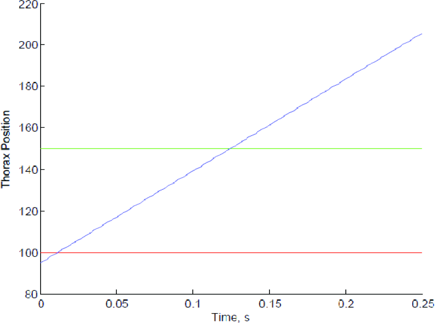
Thorax position.
With the above data, both angular and linear velocities of the numerical example are calculated. The resulting time history of the linear velocity components of the centre of thorax using the screw theory is shown in Fig. 10. Angular velocity is shown in Fig. 11.

Linear velocity of the Hex-piderix robot.
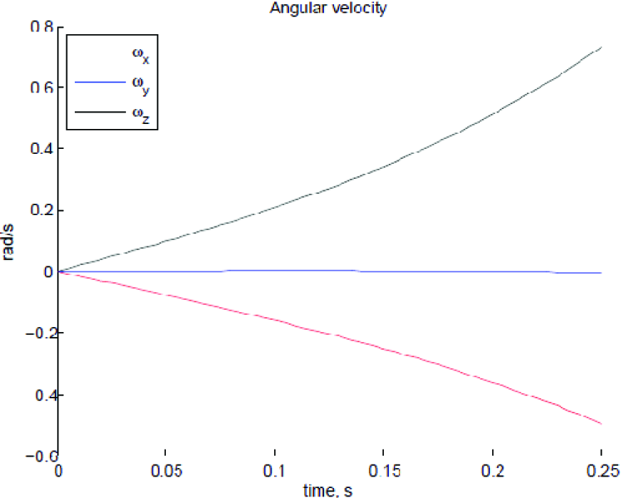
Angular velocity of the Hex-piderix robot.
As is shown in Figs. 8 and 9, the components of the position vector of thorax are not constants due to suction cup deformations; hence the angular velocity is different to zero.
6. Conclusion
It was developed a method to determine the rotation matrix of the thorax of a legged robot with respect to the global frame, without having to use trigonometric functions, since these could lead to ambiguous values for the orientation. Although, this method is usually applied in the study of parallel robots, it can be successfully employed in the analysis of legged robots.
The velocity and acceleration states of the thorax with respect to the fixed platform are written in screw form through each one of the three limbs of the robot. The equations obtained are linear, simple and compact through the use of the Klein form of Lie algebra. In addition, it is not necessary to know the velocities and accelerations of passive joints to solve forward velocity and acceleration analysis, respectively.
This kinematics study provides the basis for generating control strategies that allow the robot to recover from perturbations during locomotion, as well as keeping the thorax in a constant orientation.
It would be helpful to consider the suction cup attached to each tip of the tibia when modelling the kinematics of a legged robot, as this can introduce an error.
Footnotes
7. Acknowledgments
The authors acknowledge to the SIP-IPN for funding the research project 20121376