
Abstract
This article describes the way in which six nontraditional legs collaborate to provide locomotion to a walking machine when it moves along a path. Such legs are based on the one-degree-of-freedom Peaucellier–Lipkin mechanism, which was modified by the addition of four degrees of freedom. Such five-degree-of-freedom legs have the ability to adapt their postures according to the center of rotation around of which the machine walks. The attributes and abilities of the hexapod are expressed by means of a mathematical framework, which grants the spatial description and required joint variables, according to a specific task, resulting in the configuration of its legs for a particular path planning. Additionally, the article presents an illustrative example describing a detailed procedure concerning the configurations and collaboration of their legs according to an imposed center of rotation around of which the six-legged robot walks.
Introduction
The aim of this article is to present an algorithm concerning the locomotion process of six nontraditional legs mounted on a pelvic structure of a walking machine. This algorithm is supported by a mathematical structure processing the input conditions of the path along of which the machine walks and, as a consequence, providing the precise reconfigured posture and collaboration of each leg for the correct walking gait.
Legged systems are able to traverse more difficult terrain than wheeled or tracked vehicles. This advantage is obtained due to their abilities to place their feet on desired footholds. Once reachable footholds have been chosen, inverse kinematics and joint motors position feet on the footholds. 1
Although specialized literature shows a rich knowledge, dealing with walking machines using a huge diversity of legs, this investigation has found a lack of information concerning apparatuses equipped with legs based on the Peaucellier–Lipkin (PL) mechanism, except those mechanical systems described by Núñez-Altamirano et al. 2,3 Juárez-Campos et al. 4 and Godoy et al., 5 which deal with the same robotic leg presented in this article and the leg of a biped nonanthropomorphic exoskeleton.
Most walking machines use devices designed from traditional mechanical architectures coupled by either revolute or prismatic joints. Some examples are the Cartesian, cylindrical, spherical, or SCARA architectures. However, legged robot locomotion mechanisms are often inspired by biological systems. 6
In Figure 1, we show the same nontraditional six-legged machine, presented by Núñez-Altamirano et al., 3 whose legs are redundant five-degree-of-freedom (DoF) robotic locomotion units, based on the PL linkage, 2 –4,7 as the one shown in Figure 2. Typically, a robotic leg should have three DoFs for positioning. More than three is referred to as kinematically redundant leg, 8 nevertheless, the extra DoFs found in redundant positioning devices are conveniently exploited to meet a number of additional constraints on the solution of the inverse kinematics, 9 to generate an internal joint motion that reconfigures the structure according to given task specifications, 10 and to obtain a more versatile positioning device in terms of its kinematical configuration and its interaction with the environment. 11 Thus, redundancy is a source of freedom in task execution, because it provides the robot mechanism with an increased level of dexterity. 12

Hexapod with five-DoF legs based on the PL linkage. 3 DoF: degree of freedom; PL: Peaucellier–Lipkin.

This redundancy is greatly exploited by the PL-based robotic leg presented in Figure 2, by means of three of its DoF, which adapt or configure the leg according to the curvature of the path. 2 –4 This article and the one presented by Juárez-Campos et al. 4 show that three DoFs are dedicated to configure the leg according to the required task. Once the leg is configured, only the remaining two DoFs are driven to provide the walking travel in agreement to the support and transfer phases exerted on foot during the gait. 4 This process of walking is different from the one exerted by traditional mechanical architectures, which ordinarily requires three DoFs, which are coordinately controlled, to move the whole leg and position its foot.
Thanks to its redundancy, the PL-based leg is able to adapt its inner structure to provide a wide range of geometric paths including straight lines, concave, and convex circular curves, all they needed to provide a well-structured walking process along a common road. It is important to emphasize that a structured road is composed by a set of circular curves and straight lines serially connected. 2 The correct interaction of the six PL-based legs provides an effective maneuverability on the resulting walking machine. It can walk along straight lines, curves as well as diagonally or from side-to-side motions. This set of skills includes forward or backward walking, rightway and leftway walking as well as clockwise and counterclockwise turning, in consideration of the transverse, frontal, or sagittal planes of motion, according to the approach given by Takanishi et al. 13
The walking machine can be used in agricultural activities because of its load capacity and its ability to describe exact trajectories.
The most important advantages in the use of the PL robotic leg, compared with other mechanical leg architectures are that: (1) it is based on a parallel linkage with eight bars, it distributes forces and torques in a superior manner than open or serial kinematic chains, and (2) is capable to generate paths in a given space with only two DOFs, once it is reconfigured, compared with traditional propulsion units that require at least three DOFs per leg.
Aim and scope
This article considers the five-DoF robotic leg presented and published by Núñez-Altamirano et al. 2,3 and by Juárez-Campos et al. 4 None of them, however, has addressed the operation of a hexapod machine that uses such robot legs. The aim of this article is to show the way in which six five-DoF legs, based on the PL mechanism, collaborate in providing locomotion for the robotic vehicle along a circular path, according to the particular center of rotation of the road. This collaboration considers the traditional periodic tripod gait generation because it can be easily controlled and has an optimal stability margin. 14
The scope of this article considers the use of the mathematical modeling concerning each leg and the spatial description of the set of legs and pelvic mechanical structure conjoined by the condition of a specific task. This conjunction results in a theoretical simulation of the machine providing an overview about the particular hexapedal gait concerning this kind of legged robots.
Contribution
After examining the literature, we have not found information revealing the collaboration of six five-DoF PL-based legs, as the ones presented herein, providing locomotion to a walking machine. So then, we contribute in the field of robotics, in showing the way in which six PL-based legs work together with the purpose of transporting the robotic body along a defined path.
Article organization
The contents of this article include seven main parts. After this introduction, the second part describes the background and state of the art concerning several mechanical architectures of robotic legs and walking machines. Considering that the strategy of a legged robot in the walking process depends mostly on the characteristics and attributes of their legs and is affected by the number of them, 15 the third part offers a comprehensive study on the attributes of the robotic PL-based leg. Although it has been previously presented by Nuñez-Altamirano et al. 2,3 and by Juárez-Campos et al., 4 in this part, we show the concepts of concavity and convexity, which are related to the variation of the lengths of two constitutive adjustable links. Concavity and convexity are the strongest supports on which the PL linkage gets the attention to be used as a robotic leg. 4 The fourth part deals with the spatial integration of six PL-based legs onto a pelvic structure. Such spatial description makes use of the forward and inverse kinematics, implicating only the position and orientation descriptions. In fifth part, and by means of an example, we offer a walking process algorithm, in which the six-legged robot moves around a vertical axis passing at the center of curvature of a path. The first steps of this algorithm refer to the configuration process of the PL-based legs, in which every leg reconfigures itself by means of a particular internal joint motion. This process is called Rotation Center Tuning (RCT). 4 Last steps present the way in which the robot performs the gait along the path. Finally, we provide a computer-based simulation about the collaboration performed by the PL-based legs, present the main results, and conclude.
Background and state of the art
After examining the literature, we concluded that in recent years, there has been significant progress in the technology of legged robots, primarily hexapods and quadrupeds. Hexapod robots are normally chosen because of their better stability and higher number of different gaits. The greater stability of hexapods becomes an advantage because it eases control. 16
The robotic vehicle presented in this article has a kind of legs that has been described in three previous articles. The first one, presented by Nuñez-Altamirano et al., 2 explains the skills by means of which the PL-based leg reconfigures itself according to the spatial descriptions of three points found on the route where the robotic machine walks. The second one, written by Núñez-Altamirano et al., 3 formulates the dynamics of a single PL-based leg when it executes the swing phase along a straight path. The third one, reported by Juárez-Campos et al., 4 explains the origins of conception of the PL-based leg. It was inspired by the sprawling leg postures of some reptilian animals. In this third article, the authors discuss and provide logical arguments about the integration of five actuators among a tangle of links forming two PL structures. Both of them provide the necessary stiffness and mobility of the PL-based leg. They also introduce the concept of RCT used in the reconfiguration of the leg according to the task.
There are some good examples of hexapod robots. The Octopus-III robot is a six-legged moving platform whose legs are arranged in Universal-Prismatic-Spherical (UPS) chains driven by three linear actuators. Its motion generation method applies the tripod stable gait, meaning that three legs are in swinging sequence, while the others are in support phase. 17 The hexapod robot based on PL linkage also applies the tripod stable gait.
The hexapod robot HexbotIV is a pony-sized platform supported by six three-DoF legs structured with new hybrid mechanisms which mimic the legs of mammals. They developed a method that improves robot’s locomotion speed from 0.2 m/s to 0.54 m/s. 18
Another interesting mechanical architecture of hexapod robot is presented by Zhong et al. 19 which is a kind of Radially Free Distributed Hexapod Robot (RFDHR). It includes six identical legs mounted on a frame holding a bull gear. Each leg is composed by four links and driven by four actuators. It has the skill to rotate around its geometric center; the PL-based robot has the same skill.
ASURA I is a harvestman-like hexapod robot. The contribution of this research concerns the bioinspired design of long legs relative to its body, created in the likeness of the arthropod known as harvestman. 20
The five-DoF robotic leg presented in this article and in other works 2 –4,7 was conceived from the one-DoF PL mechanism, which is commonly referred to as Straight Line Mechanism because it uses a rotation of the input link to create a straight line motion of the output point. 21 It was invented by Peaucellier (1864), an officer of the French army, and by Lipkin (1871), a Russian mathematician. 22
The PL linkage has found several applications: as a linear haptic device, 23 as a positioning device of teleoperated needle steering systems, 24 as an actuation mechanism of deployable structures, 25 and some others. However, its use as a robotic leg is scarcely widespread. Instead, other mechanical structures have wider popularity. Literature shows that the pantograph mechanism is widely used as a robotic leg. An example is presented in the work by Tao and Marco 26 : the LARM leg uses a Chebyshev four-bar linkage and a pantograph mechanism. The quadruped robot, presented in the study by Spröwits et al., 27 uses a leg configuration, which is based on a spring-loaded, pantograph mechanism with several segments. A pantograph-jack structure as leg is described by Ishihara and Kuro. 28 Another walking machine with nontraditional legs is presented in the study by Saranli et al. 29 : the RHex robot consists of a rigid body with six compliant legs, each possessing only one independently actuated revolute DoF. Doroftei and Baudoin 30 describe a hexapod robot named AMRU5. The leg structure is based on a pantograph mechanism that comprises two loops, one of parallelogram type. They say that this leg has some advantages. It generates an exact straight-line on the two axes on the Cartesian coordinate system. This means that for a walking on a smooth terrain no more than two motors are actuated at the same time. It provides good energy efficiency (less energy consumption) due to the completely decoupled foot motions and exact straight line motion characteristic. It has a good rigidity and a simpler control algorithm due to the completely decoupled motion and linear relationship between input and output motions. Hirose and Kunieda 31 describe the characteristics of TITAN III and TITAN IV. This walking robots use leg structures based on the pantograph mechanism, similar to the one described by Doroftei and Baudoin. 30 They also affirm that this mechanism provides enhanced energy efficiency and can simplify the control of the leg motion.
The patent document presented in the study by Juárez-Campos et al. 7 describes the addition of four more DoFs to a PL-based leg. The added independent joints permit the foot of the PL-based leg to follow straight lines, concave or convex circular curves, which are needed to command the correct motion of the whole walking machine. The resulting legged robots, presented in the study by Núñez et al., 32 are capable of walking through straight paths or rotating during orientation about a wide number of rotation axes placed at different points, lying on the horizontal plane of displacement. The patent documents indicated by Juárez-Campos et al. 33,34 describe two different six-legged walking machines that make use of PL-based legs. They use a minimum number of actuators with the aid of rigid mainframes which use golden ratio measures 32 and mechanical transmissions linking several joints which become dependent. The article presented in the study by Godoy et al. 5 and the patent application document presented in the study by Juárez-Campos et al. 35 present a biped walking exoskeleton or wearable robot whose three-DoF legs are based on the PL mechanism. Such legs are able to reproduce human walking nicely. Núñez-Altamirano et al. 3 present the dynamic analysis of the PL-based leg to obtain the actuator torques when it executes a straight path during the transfer phase. It is not intended to show the process by which the leg reconfigures itself, nor does it show its integration onto a pelvic structure, nor does it show a walking process.
With respect to the path and trajectory planning, and gait generation, Zhang et al. 36 use a high-order polynomial describing the trajectory model and propose a new motion planning theory which is aimed at the adaptation of hexapod robots to more complex terrains. Zhong et al. 37 propose a central pattern generator-based locomotion control and gait planning for a RFDHR. Ya-Xin and Bo 38 proved that their experimental walking robot could walk smoothly without obvious body undulation by a proposed method controlling the foot trajectory of each leg, which is optimized by genetic algorithms to minimize energetic cost; it was proposed with two different gait patterns. Wang et al. 39 propose a gait-generated method constructed by a support factor and a delay factor, which describe locomotion efficiency and leg difference motion, respectively. Zhao et al. 17 present a novel obstacle avoidance and motion planning scheme for the hexapod robot called Octopus-III. This scheme is inspired by the superior mobility of the legged robot. The approach coordinates the body motion and the feet motions to fulfill requirements of walking stability and kinematic feasibility, simultaneously.
The robot, whose legs are based on the PL mechanism has good adaptability to the terrain, similar to most of the analyzed robots, with the advantage that it uses only two DoFs for walking after reconfiguration, in comparison with the propulsion units previously analyzed that require at least three DOFs per leg. The maximum speed reached for the PL linkage robot is approximately 70% less than that improved by HexbotIV.
Description of the five-DoF PL-based leg
Although the PL-based leg has been previously described by Núñez-Altamirano et al. 2,3 and by Juárez-Campos et al., 4 in order to provide independence and continuity in the reading of this article, we have decided to rewrite some important parts of its description.
According to some authors, legged robots can be grouped into mammal-type and sprawling-type. 4,40 The robotic leg presented in this article belongs to the second group. Walking machines that have sprawling legs are quite stable because legs in supporting phase provide large stability polygons. Additionally, these machines have low centers of mass. 4,41 –43 These are the reasons that motivated the development of this hexapod with these sprawling robotic legs. Nevertheless, a sprawling leg provides a slower speed during walking and the necessity of the design of a strong structure, representing the proximal linkage of the leg, which comes from the fact that the sprawling posture results in large joint moments or motor forces. 40 As shown in Figure 2, it can be seen that the robotic leg is made up of a strong structure capable of supporting its own weight and the load it carries.
The five-DoF PL leg, presented in Figure 2, makes use of five actuators driving the independent joints. Three of them are linear while the remaining two motors are rotational. 2 –4,7 The hexapod presented in Figure 1 and described in the work by Núñez-Altamirano, 3,32 uses such legs.
Figures 3 and 4 provide top and side views of solid models of the PL-based leg. Figure 3 shows its revolute joints A, B, C, D, E, and F, while Figure 4 presents the linear actuator whose function is to ascend or descend the robotic foot to different heights with respect to the floor.


In order to make easier for the reader to follow the explanation, we use a simplified sketch of the top view of the PL-based leg presented in Figure 3. This simplification is presented in Figure 5, showing six solid lines and two dashed segments connected by six revolute joints, named as points A, B, C, D, E, and F. Lines connecting points i and j are represented by symbols

Top view of a simplified sketch of the leg.
There are two sets of solid lines:
Lengths of solid lines.a

a In all cases,
In order to explain the addition of four more DoFs to the basic PL mechanism, consider Figure 6, whose all bars are rigid and lengths of links

Basic planar one-DoF PL linkage, where
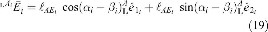
Now, we add a new DoF to the basic planar one-DoF linkage presented in Figure 6. This new DoF rotates the whole leg around an axis at point A. This angular motion is now measured by θA. It means that

Addition of the new DoF, θA, to the basic planar one-DoF PL linkage. Now, the mechanism has two DoFs. They are θA and θB. DoF: degree of freedom; PL: Peaucellier–Lipkin.
Due to the fact that
At the moment, the PL-based mechanism is able to trace straight paths and change its orientation; nevertheless, if we want to consider the mechanism as a robotic leg, it must be able to trace curved paths. The PL mechanism traces a straight line because
In Figure 8, we present a new mechanism, which is different to the one shown in Figure 7. They are different because the one shown in Figure 8 has links


Schematic representation of four DoFs, θA, θB, dAB, and dBC. DoF: degree of freedom.
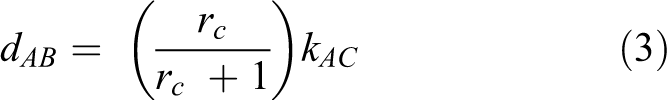
Although dAB and dBC act independently, the mathematical structure presented in this article considers the restriction given in equation (2), where kAC is a constant

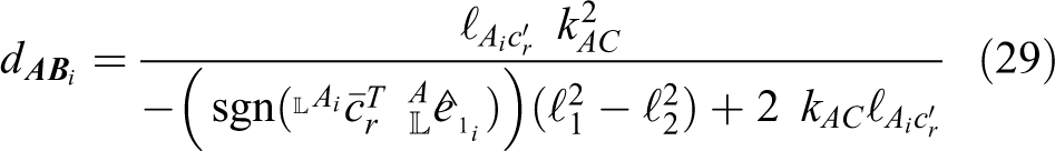
According to equation (1), the possible consequences occur when: (i) rc = 1, the path followed by point F corresponds to a straight line. See Figure 9. (ii) rc < 1, then the path followed by point F corresponds to a concave circular curve (the observer is placed at A). When rc is decreasing with respect to the unity, the center of the circle moves toward point A, which is always found between the center of the circle and point B. See Figure 9. (iii) rc > 1, the path followed by point F matches a convex circular curve (the observer is placed at A). When rc increases with respect to the unity, the center of the circle moves toward point A. Point B is always found between the center of the circle and point A. See Figure 9.

A PL-based leg presented in three different postures and paths followed by point F. Although, all the sketches have the same kAC, each one has a different configuration: (a) rc < 1 and
Finally, consider Figure 4, which provides a side view of the PL-based leg. It shows how a linear actuator reduces or increases the vertical distance between the main body of the leg and the foot. The involved distance is symbolized by dF and represents the fifth DoF.
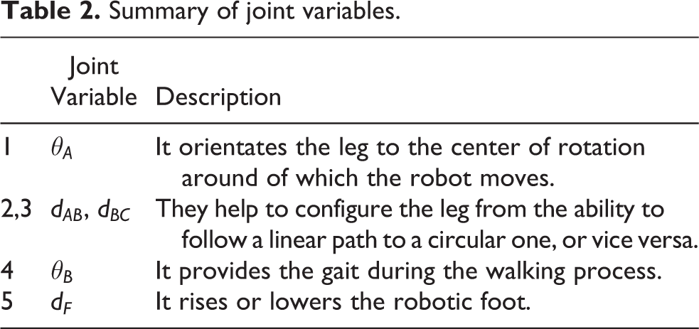
The above description has shown the five joint variables, representing the five DoFs belonging to the PL-based leg. See Table 2.
Summary of joint variables.
According to equations (1) and (2), dAB and dBC can be expressed as function of rc and kAC, see equations (3) and (4)

Considering equations (3) and (4) and Figure 9, case 1 occurs when rc = 1, case 2 takes place once rc < 1, and case 3 happens while rc > 1. Figure 10 shows a 3-D plot that considers

Variation of dAB and dBC.
Spatial description
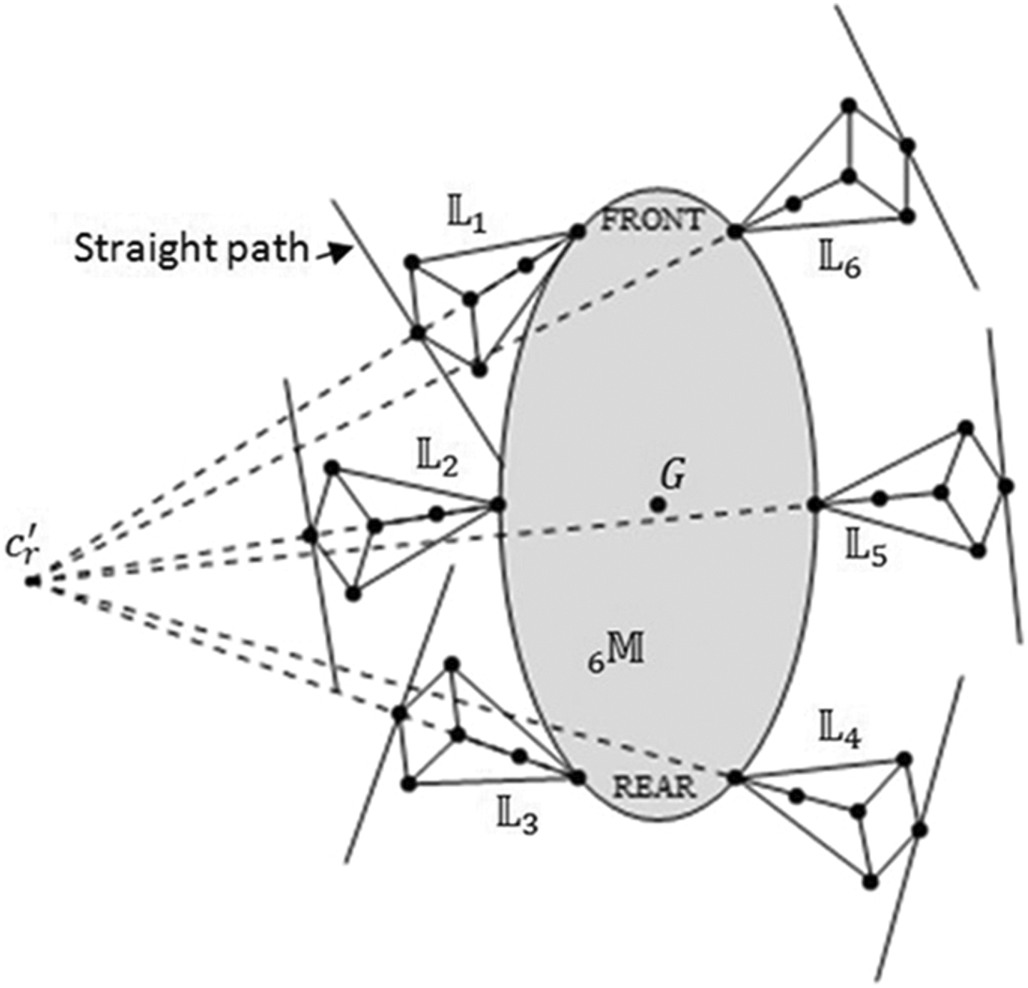
Figure 11 shows a top view of a sketched hexapod,

A sketch of the hexapod.
In order to define the spatial description of the walking machine, it is necessary to establish
Additionally, several orthogonal coordinate systems have been placed at convenient points on

Reference systems attached to
Otherwise, as shown in Figure 13, legs

Reference systems
Finally,
Coordinate systems {U}, {G},
In this manner, there is a spatial description concerning every two reference systems. See equations (5) to (9)


where
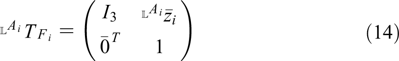
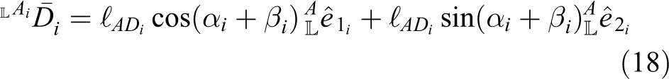
In order to change descriptions from frame to frame, we use homogeneous transformations:
which are shown in equations (10) to (14)


Direct kinematic analysis
Joints of


where


Each foot position is described with reference to

Inverse kinematic analysis
In order to command the robot to move to a final location, it is necessary the use of inverse kinematics. When inverse kinematics of one leg is computed, it is indispensable to solve joint variables as function of the operational data obtained from the task, which are the desired position of the center of rotation, cr
, around of which the machine walks and the required position of the foot. So, inverse kinematics consists in finding

where

Next sections present joint variables given in equation (25) expressed in terms of the elements of
Calculation of
In order to walk around a vertical axis passing at point cr
, which is the center of rotation placed on the ground, it is necessary to make matching two different points:

where

Points ci
and
According to Figure 14, points
The first step, which has to be executed to make matching

where

In this way, when
Once the first step has been executed, the next one consists in nullifying the difference between
Calculation of
and
Once

Geometry describing concave arcs.

Geometry describing convex arcs.
As shown in equations (29) and (30),
Thus

where
Thus, it is clear that
Now, the remaining joint variables,
Calculation of
According to geometries shown in Figures 16 and 17,

where

and
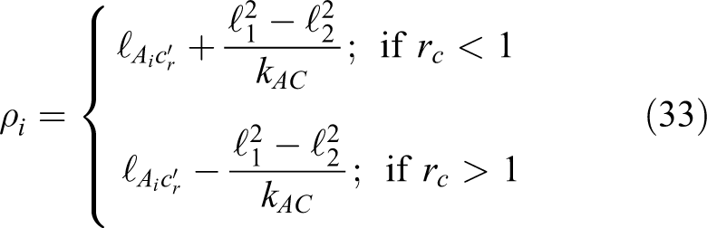

Considering equations (31) to (33), legs collaborate when the arc lengths traced by
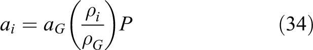
where ai
is the arc lengths described by points Fi
; i = 1, …, 6. aG
is the arc length along the walking machine moves. ρi and ρG are the radii of curvature concerning

Calculation of
Joint variable

During the transfer phases,
In order to collaborate,

Example
In order to clarify the mentioned mathematical frame, this article provides an example, which illustrates the functionality of the actual six-legged walking machine,
The example introduces the way in which
Mainframe

Constructive parameters of
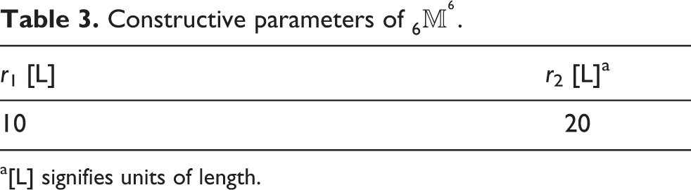
a[L] signifies units of length.
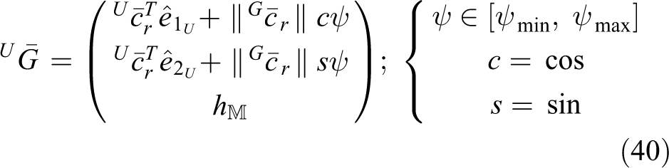
Points
Legs
It has been said that a PL-based leg has 2 sets of rigid links:
Constructive parameters of

a[L] signifies units of length.
Conditions of walking
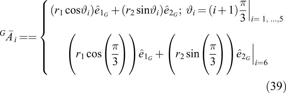
The hexapod
After the RCT process, the geometric center of the walking machine, denoted by point G, moves along the arc length aG
, given in Table 5, coincident with the circular path shown in Figure 21. Its coordinates are given by equation (40), when ψ varies from ψmin to ψmax, given in Table 6, where
Parameters dealing with the path followed by G.a

a[L] means units of length.
Parameters dealing with the path followed by G.a

a[L] means units of length.
Besides,
Configuration process
Figure 17 shows the initial pose of
Step 1: Use equation (28) to compute Step 2: Use equation (27) to calculate Step 3: Keep feet Step 4: Rotate Step 5: Put feet Step 6: Lift feet Step 7: Rotate Step 8: Put feet Step 9: Use equations (29) and (30) to calculate
a Given in units of length [L].


Values of
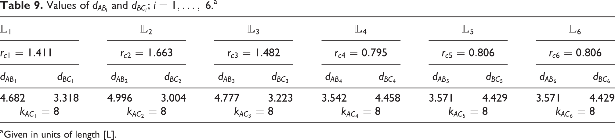
a Given in units of length [L].
Figure 21 shows

Radii of curvature traced by legs.
Figure 22 puts on view how point B
1, of

Detailed view of leg
At this moment, the robotic legs are configured or prepared to let
The next steps consist in executing the gait. Figure 23 shows the initial posture, which is the same one presented in Figure 21, and the final desired posture, obtained when its geometric center, G, reaches the new position, G′, during its translation along an arc coincident with the circular path as a result of the rotation around
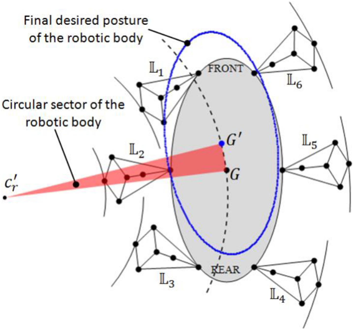
Final desired posture of the robotic body.
Before the execution of the gait, we discuss the next fictitious case. Firstly, and according to Figure 24, we consider that the body of the robot is motionless and in the same position and orientation as those shown in Figure 21; in addition, all the legs are in flight or swing phase. Legs 2, 4, and 6 form a tripod of equilibrium and simulate the action of rotating the body of the robot counterclockwise. Legs 1, 3, and 5 move in such a way their actions mean a rotation of the robot around the center of rotation in a clockwise direction.

The fictitious case in which the robotic body is motionless and the robotic legs perform a simulated gait.
In Figure 24, all legs have been coordinated in such a way as to simulate the translation of point G, along the desired arc presented in Figure 23. Furthermore, Figure 21 presents the walking robot when angles
Figure 24 shows the different circular sectors described by the translations of points Fi
; i = 1, …, 6 along their arcs. These sectors have equal angles, but, due to their different radii of curvature, the travels of points Fi
; i = 1, …, 6 have different lengths of arc. As a consequence,
Step 10: Use equation (31) to calculate
Values of

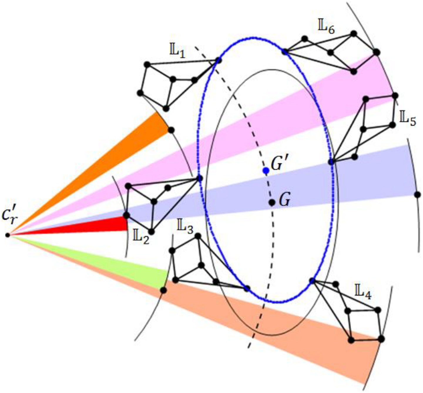
The actual case in which feet of legs 2, 4, and 6 are motionless because they are in support phases. Otherwise legs 1, 3, and 5 are in flight phases. As a consequence, the robotic body moves from G to G′ along an arc coincident with the circular path.

Final posture of the whole-legged robot corresponding to the set of angles
Figure 25 reveals the actual motion of the whole robot, whereas Figure 24 presents the fictitious case in which the robotic body is motionless and its legs perform a simulated gait. In both postures, the arrangements of legs with respect to the body are identical. Posture in Figure 25 results when the one in Figure 24 ‘is pushed’ along the circular arc that point G must describe. Due to the fact that feet of legs 1, 3, and 5 are in flight phase, each foot is moved twice the length of arc that it performs by itself. It means that the circular sectors described by legs 2, 4, and 6 in Figure 24 do not exist in the nonfictitious case (Figure 25), and the arcs described by legs 1, 3, and 5 have double lengths with respect to the fictitious case (Figure 24). This explanation is depicted by Figure 25.
In Figure 26 we show the initial posture, shown in Figure 21, and represented in dashed lines, and the final one, accompanied by the circular sectors that points G and Fi of legs 1, 3, and 5 perform during the gait.
Step 11: Now, let legs 1, 3, and 5 be in support phase and legs 2, 4, and 6 in flight phase. At this moment, the walking machine is able to perform a new translation along the circular path, see Figure 27, which represent the final position and orientation of the walking machine.

Final position and orientation of the whole legged-robot.
Simulation
Once the reconfiguration process is achieved, the robot performs the gait, executed by
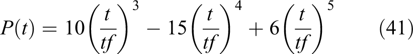
The use of equations (31) to (35) and (41), when t evolves from 0 s to tf
, shows the manner in which

Evolutions in time of
Figure 29 shows the evolution of

Evolutions in time of
The gait also includes the evolution of


Values of

a [L] means units of length.
The evolutions in time of

The dynamic evolution in time of the two tripods.
Figures 28 and 30 show the collaboration of all legs in time. We can see that the gait concerning the tripod in swing phase is performed by the aid of two actuators per leg, which must evolve coordinately, whereas the tripod in support phase needs the evolution in time of only one actuator per leg. It represents the control of 9 actuators, instead of 18 motors concerning a hexapod with traditional three-DoF legs. Of course, it is only possible after the configuration process.
Conclusions
In this article, we present an algorithm providing the steps in which a nontraditional six-legged robot is prepared according to the conditions of the task and how it performs the walking gait. The hexapod is presented as a nontraditional one due to the mechanical architecture of its legs which are based on the one-DoF PL mechanism, whose modification to a redundant five-DoF linkage has not been widely treated before as a robotic leg. The redundancy of their legs provides some advantages because after a prior configuration, every leg uses, at most, two actuators to provide the walking gait along straight or curved paths. When the leg is in support phase, it uses only one actuator. Other traditional robotic legs need the actuation of their three independent motors for positioning to achieve the same task. It is true that every leg has more than three motors, but, when the leg is configured to a particular and constant path, these extra motors stay motionless. It is inferred that the control strategy is simpler when only one or two motors is or are moved, coordinately, at the same time, instead of three actuators. Considering that any path, along of which the machine moves, is compound by straight lines and circular curves, which are easily traced by the PL-based legs, due to their specialization, the control becomes more attractive when there is a smaller number of motors.
The achievements and contributions of this research work are summarized (a) in the creation of a six-legged robot with nontraditional structure, reconfigurable thanks to the kinematic redundancy of its legs, which are based on the defined path tracing mechanism, and (b) the corresponding set of steps or algorithm, supported by a mathematical structure, that allows us to develop a walking process along paths composed of straight lines or circular curves, only achieved by the collaboration of their legs.
Footnotes
Declaration of conflicting interests
The author(s) declared no potential conflicts of interest with respect to the research, authorship, and/or publication of this article.
Funding
The author(s) received no financial support for the research, authorship, and/or publication of this article.
Supplemental material
Supplemental material for this article is available online.
References
Supplementary Material
Please find the following supplemental material available below.
For Open Access articles published under a Creative Commons License, all supplemental material carries the same license as the article it is associated with.
For non-Open Access articles published, all supplemental material carries a non-exclusive license, and permission requests for re-use of supplemental material or any part of supplemental material shall be sent directly to the copyright owner as specified in the copyright notice associated with the article.