
Abstract
Development and deployment of new drives using reducers is exactly dependent on their area of application. Designing a universal drive is complex and cannot be done without various compromises. When installing the drives into the robotic arm nodes used on the chassis of the mobile service robots, it is also necessary to provide suitable input voltage values for operation on the built-in batteries. To provide the desired results, it is sometimes more suitable to have actuators with various configurations which, however, leads to the need for a comparison between them. Testing stands of drive manufacturers are designed to test drive parameters that are standard version. For the development of new drive configuration with the use of secondary transfer, it is necessary to implement the specific verification stands, which allows for comparison between the properties under the same test conditions. Drives equipped with accurate reducers are very sensitive to the choice of the correct methodology for measuring, because their declared repeatability is less than 1.5 arcmin. The article describes the relative positioning accuracy of the resulting configurations of the two actuators, one of which uses a secondary belt drive and the other uses a flexible coupling for linking the motor and the reducer. For the avoidance of production inaccuracies, the motor and reducer on the measured drives are the same. This means that before the verification of the first drive, it is necessary to assemble the whole system, according to the prescribed manufacturing process. After implementing the measurement, the same components are used, namely the engine and the reducer of the other drive, and the measurement is carried out under the same conditions.
Introduction
Verification of parameters of actuators used in the construction of the robotic arms for mobile service robots can be done in two ways. In the first method, the parameters of actuators shall be verified on the relevant stands. The results are used to optimize the design before the actual construction of the robotic arm. 1,2 Then, it is necessary to use the second method and measure the evaluated characteristics of the robotic arm when the system is assembled. In this case, we do not verify the properties of one drive, but the mutual features of actuators that make up the whole function structure of the robotic arm. In case we want to use the construction actuators, which are newly developed or have undergone innovation, first it is necessary to determine the parameters that require the use of specific measurement stands for nonstandard design solutions. 3,4 The proposed drive is based on the concept of the electric servomechanism designed for controlling the position of the output member of the machine or the robot system. 5 It consists of exact reducer with hysteresis value to 1.5 arcmin, the hollow shaft with inside diameter of 13 mm and the value of rated output torque of 50 N·m. The functionally crucial elements of coaxially arranged aggregate part of the drive are DC drive motor, reducer, power semiconductor converter for power and control, motor speed controller, and respective position controller 5,6 The drive must allow for four-quadrant operation, that is, both directions of rotation and both directions of torque. The drive operates in closed feedback support, with either target (optimal positioning—manipulators, positioners, positioning tables, etc.) or tracking (time optimal positional adjustment as soon as possible, following the desired path/precise input speed, multi-axis machine tools, etc.) position control. 7,8 Rotary drive module (RPM) is a newly designed board of drives based on the actuators DS manufactured by SPINEA Technologies a.s., Prešov (Slovakia). 9 It is divided into two groups, with one group under the designation RPM-A, formed by the actuators provided with a flexible coupling for easy connection of the output shaft of a standard servomotor (TG Drives, Siemens, Czech Republic) and the exact reducer. The second group under the name RPM-H, formed by the operator equipped with secondary transfer utilizing HTD (HTD 300 5M, [218 63314DS], Denver, USA) cog belt and system of pulleys with transfer 1/1. Drives RPM use exact cycloidal reducers, TwinSpin (SPINEA Technologies a.s., Prešov, Slovakia) 70TB TS (Okrajová) and TS 70H (Prešov, Slovakia). 10 The contractor of servomotor with identification number TGN3, used to verify the parameters, is TG drives, s.r.o., Brno (Czech Republic). System model for connecting modules, the RPM into higher functional units, describes the concept of solution containing, and also describes the basic principles of controlling the assembled units, Figure 1. 11,12

System model. CS: control system; CB: control block; F1: connecting flange; B: brake; SS: speed sensor; MW: motor winding; SP: supporting body; FC: flexible coupling; R: reducer; P: pulley; F2: interconnecting flange; OE: output element.
Reducer used in drives RPM-A and RPM-H has the following parameters
13
:
Type: TS 070-075-H-H13-0159; Art. number: 390072-DO21; Reduction ratio i: 75; Rated output torque TR: 50 N·m; Acceleration and braking torque Tmax: 100 N·m; Maximum tilting moment MCmax: 142 N·m; Maximum lost motion LM: 1.5 arcmin; Hysteresis H: 1.5 arcmin.
Based on anticipated areas of use (handling, decontamination, and rescue work at nuclear power plants and refineries) and used components, the maximal deviations of accuracy and repeatability of position in drives RPM-A and RPM-H were determined:
Maximal positioning accuracy AP: to 0.001 mm; Maximal positioning repeatability RP: to 0.0015 mm; Average positioning accuracy AP: to 0.0005 mm; Average positioning repeatability RP: to 0.00075 mm.
On the verified drives RPM-A and RPM-H, servomotor is used with the following parameters
12
:
Type: TGN3-0115-15-36; DC bus voltage UDC: 36 V; Rated torque Mn: 1.15 N·m; Peak torque Mmax: 3.5 N·m; Nominal power Pn: 180 W; Rated speed Nn: 1500 r/min.
The basic difference between the standard series of drives DS and individual drives RPM resides on the use of other chain members (clutch, pulley, toothed belt, and various types of sensors: temperature sensor, torque sensor, forces, vibration sensor, etc.) which allows to extend the possibilities of drives. Use of flexible coupling and the carrier body in the RPM-A allows the use of different kinds of servomotors. Dimensions of the output shaft of the servomotor will not be determinative, allowing potential customers to use the servomotors from other manufacturers. Before compiling the RPM-A, it will be necessary to select the proper size of two defining components. The first is a flexible coupling (R+W, type BKL 10, max. torque 10 N·m), 13 in which the dimension of the connecting hole is dependent on the outer diameter of the output shaft of the engine. The second component is the support body, whose choice must be implemented, that is, this component is selected depending on the dimensions of the flange of the motor used. Assembling with the main components of the drive RPM-A, is shown in Figure 2.

RPM-A. RPM: Rotary drive module.
The drive RPM-H is not using a flexible coupling, instead a secondary gear ratio is used. The secondary gear ratio is the first exchangeable component consisting of a belt drive equipped with cog belt HTD 5M. It is possible to change the extent of the ratio of transmission from the value of 1/2 to 2/1. The range of gears on the output flange of the drive is from 10 r/min to 40 r/min. The other component, which can be changed, is the system supporting body, which consists of several parts (four parts), each enabling storage pulleys’ secondary transmission and their mutual adjusting. Figure 3 shows the partial view through the drive components RPM-H.
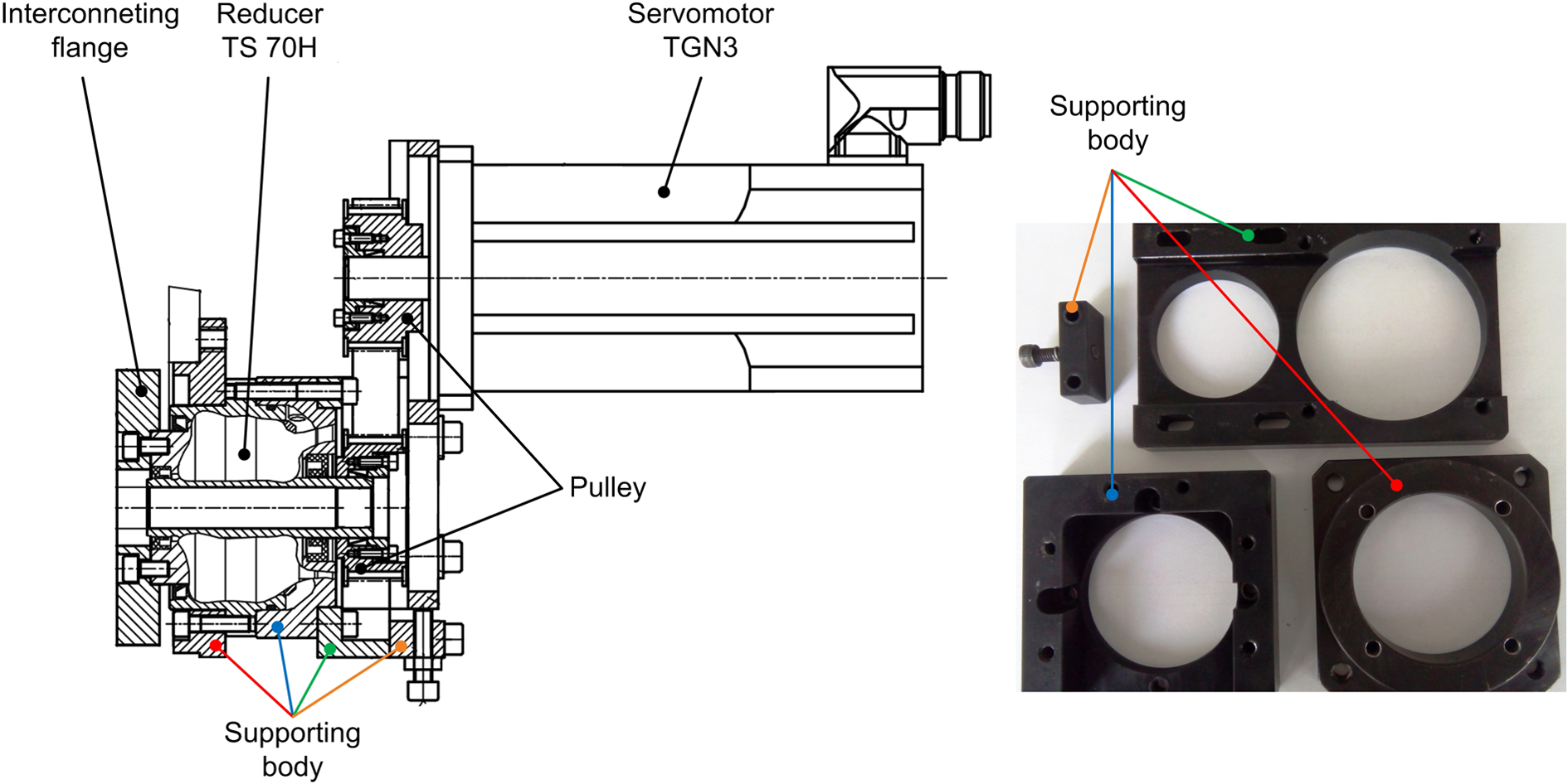
RPM-H and supporting body. RPM: Rotary drive module.
The robotic arm mounted on the mobile service robot will allow movement in six degrees of freedom. The assumed load capacity of the arm is set to 10 kg. The operating range of the arm on the robot chassis has an estimated value of 800 mm (other parameters: maximum width of the robot is 580 mm; max. height of the robot when moving is 350 mm; working time is min. 1 h; number of tools is 3; and obstacle height is max. 80 mm). The robot chassis for motion utilizes two major passports and two swinging arms to improve terrain patency and overall stability. The mobile service robot is designed for use in both stationary and used nuclear power plants. The visualization of a 3D model robot equipped with robotic arm is shown in Figure 4.
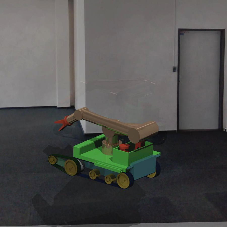
Mobile service robot.
Choice of measurement tests
Measurement tests are based on ISO 9283 aimed at manipulating industrial robots—performance criteria and related test methods. 14,15 From the above standards, such tests were chosen to ensure the realization of detection and comparison of the required characteristics. Selected tests with the definition of the load, the output speed of rotation, and the number of cycles are shown in Table 1.
The selected measuring tests.

AP: pose accuracy; RP: pose repeatability
For the selected tests, corresponding sheets have been developed. From the individual methodical sheets after the amendment of the measured values, partial measurement protocols as part of the measurement protocol for RPM drives can be generated. 16
The measuring system used to implement the measurement consists of encoders from Heidenhain MT25 (sensor S1) and evaluation unit Heidenhain VRZ 401. The location of sensor is realized in one plane with a measuring ball, Figure 5. As the ball would crash into the measuring sensor after implementing one rotation actuator, it is necessary to realize the turning outside of measuring place. Due to this reason, the actuator is arranged on the translational axis. The translational axis consists of a rail line (HGW 15CC a HGR 15R), ball screw (R08-25T2), and DC motor (Faulhaber 3257G024CR) planted with a planetary gear of the gear ratio 38/1. 16 –18 Ejecting of the actuator from the measuring place takes 3.8 s and the length which must be overcome has a value of 180 mm.

Sensor location.
One-way pose accuracy (AP) can be defined as the difference between the programmed position, which should be achieved theoretically, and the average position that the output flange engine RPM actually achieved.
19,20
For correct measurement, it is necessary to ensure that the outlet flange of the drive RPM (on which there is a measuring ball) to the start-up of the programmed is always positioned in the same direction. From the readings obtained, one-way pose accuracy (AP) in the plane X for sensor S1 is calculated as

where (xCS) are programmed values; and

where (xjS) are real (measured) values.
One-way pose repeatability (RP) expresses the degree of agreement between the current position placements achieved by n-repetitive movements and the programmed position in the same direction. From the measured values, RP is calculated as the radius of the measuring ball whose center is the barycenter, where


Coordinates of barycenter of points scored for the n-repetition of the same position are calculated according to equation (2).
Preparation and process of the measurement
General view of the measuring station is shown in Figure 6.

General view of testing stand.
The measuring station is constructed from thick-walled rectangular profiles and mounted on the measuring stand for verification of parameters of bearing reducer for maximum torque of 200 N·m. The load of actuators RPM-A and RPM-H is realized by the burden with the value of 10 kg on the arm of 0.5 m. That represents the value 50 N·m (rated output torque for reducer TS 70). The speed of rotation of the actuator is set to 20 r/min. The said value is based on the nominal rotation speed (N·m) and the gear ratio of reducer (S1).

Preparation of measurement:
Before measuring, the actuator is assembled into the configuration corresponding to the mark of RPM-A, Figure 2. Actuator RPM-A is located into the measuring station , where the measuring ball is connected to the arm with length of 500 mm and loads with the value of 10 kg. The temperature at the measurement place is in the range of 20 ± 2°C. Actuator has been set to the initial (zero) position. After completing measurement on the actuator RPM-A, disassembling follows. Before next measurement, the actuator is assembled into configuration corresponding to the marking of RPM-H, Figure 3.
Process of measurement:
Touching of the sensor Heidenhain is moved away from measuring balls into the starting position. Actuator, after running through the translational measurement unit, leaves the measuring place and ejects by the value of 180 mm, which abuts on end backstop. The speed of moving has the value of 47.4 mm/s. The programmed cycle of rotation of the actuator starts with the following steps:
Execution of 10 turns of the actuator in a clockwise direction with a continuous easing is realized. After stopping the rotation, 10 turns of the actuator in a counterclockwise direction with a continuous easing are realized. Actuator, after completion of the measurement using the translational unit, returns to measuring place where it abuts on end backstop. The speed of moving has the value of 47.4 mm/s. Touching of the sensor is moved from the starting position to the measuring position (touches measuring ball). After stabilizing the sensor, which takes 2 s, the reading of the measured value to the evaluation unit is realized.
Results and discussion
One-way pose accuracy (AP)
Graphical representation of measured data of one-way pose accuracy for actuators RPM-A and RPM-H is shown in Figures 7 and 8.
Pose accuracy RPM-A. RPM: Rotary drive module.

Pose accuracy RPM-H. RPM: Rotary drive module.
After realizing the 30 measurements at full load of actuator RPM-A, we have arrived at the following average value of one-way pose accuracy

After realizing the 30 measurements at full load of actuator RPM-H, we have arrived at the following average value of one-way pose accuracy

One-way pose repeatability (RP)
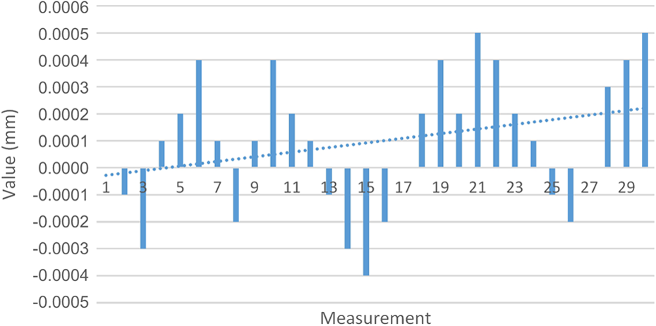
Graphical representation of measured data of one-way pose repeatability is shown in Figures 9 and 10.

Pose repeatability RPM-A. RPM: Rotary drive module.

Pose repeatability RPM-H. RPM: Rotary drive module.
After realizing the 30 measurements at full load of actuator RPM-A, we have arrived at the following average value of one-way pose repeatability
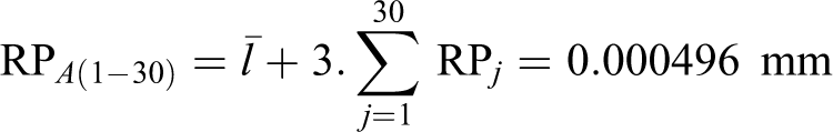
After realizing the 30 measurements at full load of actuator RPM-H, we have arrived at the following average value of one-way pose repeatability
Mutual comparisons of actuators RPM-A and RPM-H in verifying one-way pose accuracy (AP) and one-way pose repeatability (RP) confirmed the negative impact of the secondary gear ratio. Based on Figures 11 and 12, it can be stated that better accuracies and repeatability were reached by actuator RPM-A.

Mutual comparisons (pose accuracy).

Mutual comparisons (pose repeatability).
Verification of basic parameters of actuators RPM confirmed the requirements, which were placed on them in the development. Table 2 shows the average value, maximum and minimum values of AP and RP in RPM-A and RPM-H drives.
Average value, maximum and minimum AP and RP values.

AP: pose accuracy; RP: pose repeatability; RPM: Rotary drive module.
Based on the realized measurements, it can be stated that the use of flexible coupling and the secondary gear ratio has a negative impact on the results of accuracy and repeatability. It can be stated that the impact of these components does not exceed the specified limits. To confirm the realized measurements, it is necessary to implement further verifications, for example, drift position to determine whether the actuators do not lose their properties even during the 8 h working shift. Then, it will be necessary to realize further verifications for detection of minimum posing time and static compliance.
Conclusions
Based on the realized measurements of selected parameters of actuators RPM-A and RPM-H, we came to the following conclusions:
The estimated average one-way pose accuracy was not allowed to exceed 0.0005 mm (0.0005 > 0.00021). The maximum value was not allowed to run over 0.001 mm (0.001 > 0.0008). Based on the realized measurements, we can conclude that one-way pose accuracy of actuators RPM-A and RPM-H is in the desired range. Estimated average one-way pose repeatability was not allowed to exceed 0.00075 mm (0.00075 > 0.00053). The maximum value was not allowed to run over 0.0015 mm (0.0015 > 0.001). Based on the realized measurements, we can conclude that one-way pose accuracy of actuators RPM-A and RPM-H is in the desired range. The insertion of actuators into the first two axes of the robotic arm of the mobile service robot is possible and does not reduce the resulting robot accuracy parameters when the intervention is performed.
Footnotes
Declaration of conflicting interests
The author(s) declared no potential conflicts of interest with respect to the research, authorship, and/or publication of this article.
Funding
The author(s) disclosed receipt of the following financial support for the research, authorship and/or publication of this article: The authors would like to thank the Slovak Grant Agency—project VEGA 1/0872/16—financed by the Slovak Ministry of Education and also projects: Center for Research of Control of Technical, Environmental, and Human Risks for Permanent Development of Production and Products in Mechanical Engineering (ITMS: 26220120060) and University Scientific Park TECHNICOM for Innovating Applications with Knowledge Technology Support (ITMS 26220220182) supported by the Research & Development Operational Program funded by the ERDF.