
Abstract
A precision reducer with a high ratio and a small size is essential for precise control of the position of a robotic arm. The rotate vector (RV) is a reducer widely applied in robotic joints. However, its complex structure, over-positioning and difficult assembly restrict its application industrial robots. Herein, a novel abnormal cycloidal gear (ACG) reducer is proposed. In comparison to the RV reducer, the proposed reducer has the characteristics of compact structure, less over-positioning and high ratio. The compound tooth profile of “epicycloid-involute hypocycloid” is used as the driving teeth for improving the performance of the reducer. The operating principle, mechanism design and reduction ratio of the proposed reducer is investigated, and the design method of the ACG tooth profile is also introduced. A dynamic characteristic model is established to verify the correctness of the design method of the reducer. A prototype of the ACG reducer is fabricated by using the computer numerical control (CNC) machining technology. Results show that the ACG reducer is capable to cover a wide range of reduction ratios with a simple mechanism. The numerical and theoretical results are in agreement, which depict the structural feasibility and correctness of the design method of the reducer. The adaptation of the ACG tooth profile as the driving teeth helps in improving the performance of the reducer.
Keywords
Introduction
Industrial robots, which have the advantages of stable and high efficiency, are widely used in various mechanical devices, ranging from the automobile manufacturing to the electronic communications, as well as the weaponry and aerospace industries. As a typical engineering application of reducers, the modified rotate vector (RV) reducer used in robotic joints has attracted increasing attention of researchers. However, the limited volume, difficult assembly, and complex structure of the RV reducer require extremely high machining precision, thereby increasing the overall cost of the whole system.1–3 It has become the restricting bottleneck to the development of the robot technology. Therefore, the innovation of its structure and transmission principle, as well as the research and development of new high-quality precision reducers, has been the focus of the mechanical transmission system.
Extensive research has been carried out on the cycloidal drive since its invention. For instance, in order to avoid the centrifugal force, Blagojevic et al. 4 proposed a two-stage cycloidal pin gear reducer. Hsieh 5 designed a cycloidal reducer with internal gear output for solving the problem of uneven stress on gears. Jang et al. 6 introduced a new cycloidal pin gear reducer, where the transmission teeth of different heights and thicknesses can be designed. Chen et al. 7 designed a cycloidal reducer with a flexible structure and analyzed the influence of design parameters on its vibration. The application of mathematical modeling and finite element method (FEM) in the meshing theory has contributed greatly to the development of new reducers. Sun et al. 8 introduced a single-stage cycloidal pin gear reducer, and also studied the design method and efficiency loss of the reducer. Chang and Chang 9 introduced the working principle of the involute gear reducer designed by the vernier effect, and verified the correctness of the model by FEM analysis. Zhou and Yang 10 proposed a movable teeth drive with a logarithmic helix as the tooth profile, and discussed the influence of size parameters on the self-locking and force transmission characteristics of the gear teeth. Xu and Yang 11 studied the relative speed and meshing efficiency of a ball drive, and experimentally verified the superiority of the reducer. Cai et al. 12 analyzed the working principle of a two-stage nutation driven reducer, and carried out finite element analysis (FEA) of its joint components.
In addition, studies show that any variation in the tooth profile impacts the mesh properties and stability of the gear transmission. Hence, some researchers conducted intensive studies on the tooth profile design method also. In order to improve the meshing performance, Chen et al. 13 proposed a pure rolling internal helical gear drive with combined tooth profiles, and gave the design process of a circular arc-involute tooth profile through it. Peng et al. 14 proposed a circular-arc-cycloid composite tooth profile, where the obtained results showed good mechanical properties of the tooth profile. Huang et al. 15 presented a cycloidal profile of rolling sliding contact, and found that the profile has well accuracy retention. Liang et al. 16 studied a double helical gear drive with a curve element structure, and concluded that its mechanical properties are good. In order to reduce the difficulty in gear design or its size, Li et al. 17 used an arc pitch curve to replace the non-circular pitch curve, and realized the simple design of a non-circular gear drive. Zongbin et al. 18 introduced an internal meshing straight tooth drive, where both numerical calculation and experiments showed that the proposed profile can reduce the volume and improve reliability of the gear pump. The above literature review indicates that the development of new tooth profiles is an effective way to improve the load bearing capacity, transmission accuracy, and meshing performance of a gear drive.
There have been long time demands for a novel gear reducer having small volume and high ratio. But its structural design is still a complex and challenging problem. The function of a robotic joint is to drive the entire manipulator. So, it must have a large torque to meet the external heavy load. However, most reducers (e.g. the RV reducer 19 ) maintain a small difference in the number of transmission teeth, where the tooth number must be increased to obtain a large speed ratio, which will also increase largely the radial size of the drive. Due to the limited space for positing the joint of the manipulator, the size or weight of the reducer needs to be reduced further. Because of this, the contradiction between the high ratio and small volume of reducers has not yet been resolved effectively. Furthermore, with the development of the industrial technology, the requirements of high speed, heavy load, and high power and efficiency are put forward for the drive system.20,21 There is still much room for the improvement in the accuracy, dimensions, and performance of a reducer. The tooth shape design and performance analysis for different drives are also need to be explored. Meanwhile, the development of the computer numerical control (CNC) technology 22 makes the machining of complex surfaces easier, providing the necessary technical support to the research of new gear transmission with better meshing characteristics.
A novel type of abnormal cycloidal gear (ACG) reducer 23 is proposed in this paper. In this proposal, a new structure of 2K-H type inner meshing planetary reducer is adopted to tackle the RV reducer problems, such as the over-positioning problem of an eccentric shaft, and the difficulty in manufacturing and assembly. In our previous work, the meshing principle and design method of the ACG were studied. 24 It was found that ACG has a higher bearing capacity and lower sliding ratio. However, some limitations with the ACG tooth profiles were also observed, for example, it was not clear whether the given tooth profile is suitable for the ACG reducer and satisfies its meshing conditions. Moreover, vague relationships were established between the geometric parameters of the tooth profile and contact characteristics of the proposed reducer. Therefore, this article aims to study the performance of the ACG reducer, as well as the feasibility of applying the ACG tooth profile in the proposed reducer. Firstly, the structural and transmission principles of the ACG reducer are studied. Subsequently, a mathematical model of the ACG tooth profile is derived, and two gear pairs are used as a case to represent the reducer with the application of the ACG pair. Further, the reduction ratio and dynamic characteristics of the proposed reducer are studied. Finally, a prototype of the reducer is manufactured by applying the CNC machining technology. It is expected that the research presented in this paper will provide an alternative solution for joint reducers of industrial robots.
The main contributions of this paper are as follows: (1) A novel ACG reducer is proposed to solve the problems in the structure and manufacturing cost of RV reducer. In contrast to RV reducer, the proposed reducer is simpler in structure and have fewer components, making it easier to manufacture and maintain. (2) A new tooth profile is developed to improve the strength and transmission performance of ACG reducer. (3) The static and dynamic transmission performance of the ACG reducer is analyzed and discussed in detail, which can provide the basis for its transmission error optimization and test research.
Mechanism and operating principle of ACG reducer
In this section, the mechanism design, operating principle, and reduction ratio of the ACG reducer are introduced in detail.
Mechanism design
The structure of the ACG reducer is shown in Figure 1(a). It is different from the two-stage drive structure of the RV reducer (see Figure 1(b)). The first and second stage drives of the RV reducer are planetary involute and cycloidal pin gear drive, respectively. The complex structure and over-positioning problems are caused by three planetary gears with crankshafts. Furthermore, one-half of the cycloid teeth are theoretically engaged at the same time, thus requiring high mechanical properties and machining accuracy of the parts, which make the machining and assembly of the RV reducer significantly difficult. In contrast, the ACG reducer has only one planetary gear drive and its input shaft is the crankshaft as shown in Figure 2. Therefore, the parts numbering, manufacturing, and assembling of the ACG reducer are less difficult than those of the RV reducer. The structure of the ACG reducer can overcome the disadvantages of the RV reducer and realize the design with small size.

Transmission principle of: (a) ACG reducer and (b) RV reducer.

Exploded view of the ACG reducer.
The ACG reducer is mainly consists of seven basic elements: case (with internal teeth), input shaft, first ACG gear, adaptor, pin, second ACG gear and output gear (with internal teeth). In order to avoid the vibration due to the eccentricities of the gears, two gears are installed symmetrically at the phase difference of 180° on the input crankshaft to balance the centrifugal force by ensuring the transmission accuracy of the reducer. The composite tooth profile of epicycloid-involute-hypocycloid is adopted as the adaptive tooth profile of the reducer, so as to improve the bearing capacity. The design method of this tooth profile will be described in detail in next section.
The assembly relationship of the ACG reducer is as follows:
(1) The input crankshaft is supported at both ends by two bearings, and it is equipped with the eccentrically mounted first and second stage ACG pairs at a phase difference of 180°.
(2) Eight pins are passed through the adaptor by means of connections, and two ends of the pins are contacted with the holes of the ACG pair on the left and right sides of the adaptor. Thus, it forms a one-piece planetary gear carrier to ensure the symmetrical engagement of the external and internal gears of ACG reducer.
(3) The internal gear is fixed to the output shaft, and the output and input shafts have the same axis of rotation.
Operating principle
The 2-input shaft and 7-output gear of the ACG reducer are the input and output components of power, respectively. During the operation, the power is input through the 2-input shaft. Under the combined action of the 2-input shaft and 5-pin, the 3-first ACG and 6-s ACG mesh symmetrically with the 1-case and 7-output gear, respectively. Only a few teeth of the output gear are rotated per revolution of the ACG, so as to achieve the purpose of reducing speed and increasing torque.
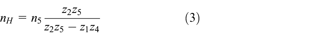
According to the above analysis, the reduction ratio of the ACG reducer can be calculated. Assuming that the speed of the input shaft is nH. The speed of case and output gear are n1 and n5, respectively. The speed of the first and second stage ACG are n2 and n4, respectively. z1 and z2 denote, respectively, the numbers of teeth on the external and internal gears in the first stage drive of the reducer. z4 and z5 denote, respectively, of the numbers of teeth on the external and internal gears in the second stage drive of the reducer.
When the case is fixed, the reduction ratio of the reducer can be obtained as:

with,

where, z1 > z5 and z2 > z4.
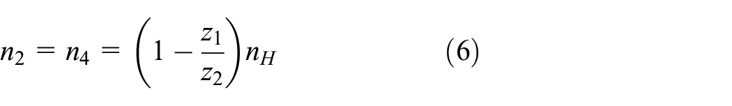
Assuming that n1 = 0, we have:
Similarly,

Further, the reduction ratios of the first and second stage drives can be obtained as:

Therefore, according to equations (3) and (4), the speed of the gears and adaptor for a given nH can also be obtained as:
Further, the speed of the internal gear in the second stage drive can be obtained as:

Additionally, the teeth assignment is also critical to the reducer design. Nevertheless, the traditional design methods mainly use the trial-and-error approach, which is blind to a certain extent. In this paper, a new method of teeth distribution based on the teeth difference is proposed.
Assume that the teeth difference between the internal and external gears of the first stage is G1, that between the internal and external gears of the second stage is G2, and that between the external gears of the first and second stages is J. Then:

So, equation (1) can be rewritten as:

Furthermore, the simplified result with z4 can be expressed as:

where, “±,” the superscript “+” means that the transmission ratio is positive, while the superscript “−” means that the same is negative. Hence, according to the above formula, for given number of teeth difference and reduction ratio, the teeth number of all the gears in the reducer can be obtained accurately.
Table 1 shows the reduction ratios of the ACG reducer under different teeth differences. It can be seen that the ACG reducer has the following characteristics:
(1) By fine adjusting the difference in the number of teeth between the first and second stage gear drives of the ACG reducer, the requirements for the reduction ratio distribution can be satisfied. This is the result of the structural characteristics of the reducer.
(2) By comparing the 12 sets of reducer parameters, it is seen that under the same number of teeth difference, the reduction ratio of the ACG reducer can be significantly changed by reasonably allocating the number of teeth at all the levels. This is a clear difference from the conventional RV reducer.
Teeth calculation of the ACG reducer.

According to the aforementioned descriptions, the significant characteristic of the proposed reducer is that even in the case of a non-small tooth difference, the ACG reducer is capable to cover a wide range of reduction ratios with a simple mechanism. It should be noted that although the ACG reducer can be obtained by using the design parameters in Table 1, however, if the teeth number is not selected properly, it can lead to an altered direction of the input and output shaft rotation. Meanwhile, if the teeth difference number between the first and second stage gears is too large, it will lead to a large volume difference between the two stage gears of the reducer. In order to balance the centrifugal force between the gear pairs, the gear with a small number of teeth needs to increase the weight, but this is disadvantaged by the light weight of the reducer. Therefore, the direction of rotation of the input and output shafts, the size and weight of the reducer should be considered during the design stage.
Generation and mathematical model of abnormal cycloidal profile
This section presents the method of generating ACG tooth profiles using a contact path, which includes the composition of the tooth profile, mathematical model of the conjugate tooth profile and design examples.
Tooth profile composition
The tooth profile is the basic factor that determines the performance of gear transmission, and the fundamental factor that affects the bearing capacity of the gears. The existing reducer transmission tooth profiles mainly include involute and cycloidal tooth profiles. However, in the context of large torque and small volume requirements of the ACG reducer, the traditional tooth profile can no longer meet the transmission needs. Therefore, we design a new composite tooth profile, that is “epicycloid-involute-hypocycloid,” as the transmission tooth profile of the reducer to improve its bearing capacity.
As shown in Figure 3(a), the tooth profile of ACG consists of three segments. The first segment is the epicycloid outside the pitch circle, the second segment is the involute near the pitch circle, and the third segment is the hypocycloid inside the pitch circle. The three tooth profiles are combined at the splicing point with C1 continuity. Since the tooth profile of ACG is both concave and convex, combining the respective characteristics of the involute and cycloidal gears, good meshing performance of the ACG drive can be obtained.

Schematic diagram of internal ACG gear: (a) tooth profile composition and (b) coordinate system.
Coordinate system and transformation matrix
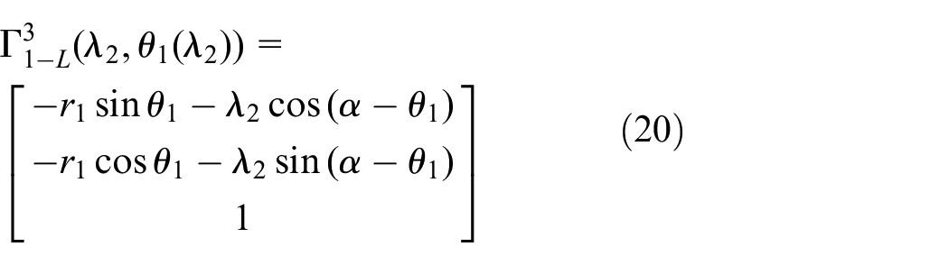
As shown in Figure 3(b), Sf– Xf OfYf is the fixed coordinate system. Conjugate tooth surfaces Γ1 and Γ2 are defined using the coordinate systems S1–X1O1Y1 and S2–X2O2Y2, which are fixed to pinion 1 and gear 2, respectively. Point M is the contact point. Pinion 1 rotates around the Z1 axis at a constant angular speed of ω1, and gear 2 rotates around the Z2 axis at another constant angular speed of ω2. After a period of time, the gear pair moves from the dashed position to the solid position, where they mesh at the node M, as depicted in Figure 3(b). Pinion 1 rotates around the Z1 axis through the angle of θ1, and gear 2 rotates around the Z2 axis through the angle of θ2. Therefore, the relationship among the above parameters can be obtained as:

The coordinate transformation from Sf to Si (i = 1, 2) is represented by the following matrix:

Mathematical model of conjugate tooth profile
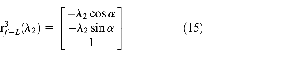
The ACG conjugate tooth profile is defined by a given contact path. Based on the conditions of ACG,
24
contact path
The position vector of

Similarly,

Further,
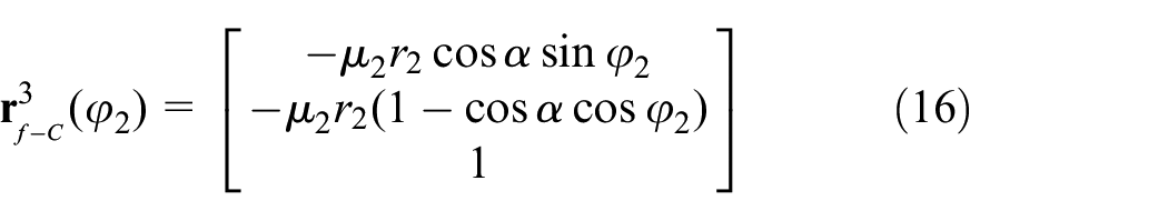
According to the meshing principle, 25 the position vector of a point on the ACG tooth profile can be expressed in the coordinate systems Si as follows:

Here, the cycloidal tooth profile generated by

The involute tooth profiles generated by

The epicycloid profile generated by

Therefore, from equations (18) to (21), the tooth profile of ACG is finally obtained. And the design flow of ACG tooth profile is shown in Figure 4.

Design flow of ACG tooth profile.
Numerical example of ACG pair
The 3D model of the gear drive of the reducer is designed to validate the tooth design method prior to analyzing the performance of the tooth profile in the ACG reducer, followed by the simulation of the ACG pair.
The modulus and teeth number are related to the eccentricity, while the eccentricity directly determines the pin hole size of the planetary gear. However, one is that too large eccentricity will increase the pin hole diameter of the gear and lead to weakening of the strength of the gear spokes, thus affecting its load carrying capacity. The second is that increasing the eccentricity will affect the dynamic balance of the ACG reducer. Excessive eccentricity will cause a large centrifugal force in both planetary gear stages, which will affect the centrifugal force balance between the first and second planetary gear stages of the ACG reducer. Therefore, the selection of modulus and teeth number should take into account the structural size, strength, and transmission stability of the reducer.
Herein, the ACG reducer with a speed ratio of 92 in Table 1 is used as a design example. In order to balance strength, transmission stability and structural size, the eccentricity of the ACG reducer is 4.5 mm, the tooth difference between the first and second stage drives is 3 and 4, and the gear modulus of the first and second stages are 3 and 2.25 mm, respectively. Other design parameters of the gears are listed in Table 2. The generating program is programmed using the MATLAB software, and then two sets of geometric models of the ACG pairs are obtained.
Design parameters of ACG pair.
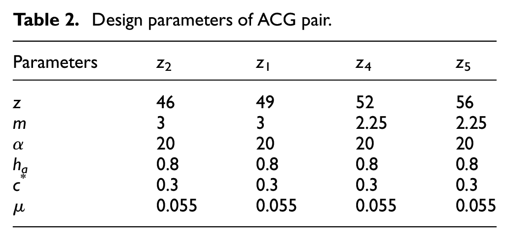
Figure 5 shows the case where two pairs of conjugate tooth profiles contact at a certain point under given parameters. It can be seen that the two sets of internal meshing ACG pairs have no tooth profile interference and they meet continuous transmission conditions, which shows the correctness of the conjugate tooth profile design method.

ACG pair with different number of tooth differences: (a) three and (b) four.
Characteristics of ACG reducer
In this section, the contact stress of the ACG pair is studied, and the dynamic performance of the ACG reducer is presented, including the reduction ratio and dynamic meshing force.
Loaded contact analysis of ACG
The loaded contact analysis can reflect the strength and meshing performance of the gear teeth. However, since the gear meshing is nonlinear, it is difficult to obtain an accurate solution by an analytical method. The FEA26,27 that can consider the material nonlinearity and has good universality, can be applied to analyze the contact characteristics of the gear. Gear drive has become an important research direction in recent years. Hence, in this paper, in order to verify the performance of the ACG tooth profile in the reducer, the finite element model of an ACG pair is established and its quasi-static meshing is also analyzed with the FEM software ABAQUS.
In order to analyze the meshing behavior of the ACG drive, we should first establish a multi-teeth meshing model and then carry out the process of multi-teeth contact analysis. For simplifying the calculation of the model, an internal meshing ACG pair consisting of a single pinion and internal gear is retained. The HYPERWORKS and ABAQUS software tools are utilized in this study. The 3D model of the ACG pair is established in SOLIDWORKS and then meshed it using HYPERMESH. Finally, the input file is run in ABAQUS/standard for loaded contact analysis. In the model, the pinion and internal gear contain 251,480 and 264,360 nodes, respectively. The model is partitioned into three sections: tooth surface (contact area), teeth, and spokes as shown in Figure 6(a). The tooth surface mesh is refined (Figure 6(b)), and the spokes are meshed using C3D8R elements. The finite element model of the ACG pair is shown in Figure 6(c).

Loaded contact analysis of ACG pair: (a) finite element model, (b) mesh of contact area, and (c) loaded contact analysis.
The involved specific operational steps are as follows:
(1) Material properties: The gear material is 20CrMnTi, having Young’s modulus is 209 GPa, and Poisson’s ratio is 0.25.
(2) Contact definition: In order to facilitate the imposition of constraints and boundary conditions, two reference points Rd1 and Rd2 are created at the geometric center of the gear, which are geometrical points that can be used in ABAQUS to simulate rigid bodies. The pinion and internal gear are selected as the master and slave elements, respectively. The normal contact is chosen to be hard contact. The friction formulation and coefficient of friction are chosen to be penalty and 0.15, respectively.
(3) Load and boundary condition: The drag torque is applied to the gear and the rotational displacement is added to the pinion. To obtain accurate results, three steps are created based on the initial step, analysis time of each of which is set as 0.1 s. Since the deformation during gear engagement, the nlgoem is selected on. Additionally, the load, boundary conditions and other settings corresponding to each analysis step are as follows:
•
•
•
•
Additionally, the output variables are also need to be defined before simulation. New field output and historical output variables, such as contact stress, bending stress, and normal contact force, should be created in Step 3.
Following the above procedures, the Von-Mises stress contours of the ACG pair are shown in Figure 7. Also, the following inferences can be drawn:
(1) In the actual contact, the number of contact teeth of the gear pair reaches two, and its multi-teeth contact meshing has occurred under the given load. It indicates that the contact ratio of the ACG drive is greater than 1, and it also has good bearing capacity.
(2) The contact trace of the ACG pair is obvious, and the contact form of its tooth surface is line contact over the full tooth width, which shows that the ACG tooth profile has good contact characteristics.
(3) The contact stress of the tooth surface is low. The contact stress of the pinion is significantly lower than that of the gear as the gear has a small wall thickness and a cantilever structure. Under the action of the component force of the meshing tooth pair, there will be eccentric load, resulting in the reduction of the contact tooth width, which will cause both the maximum local contact stress and bending stress to be large, but still within the allowable range of the material.
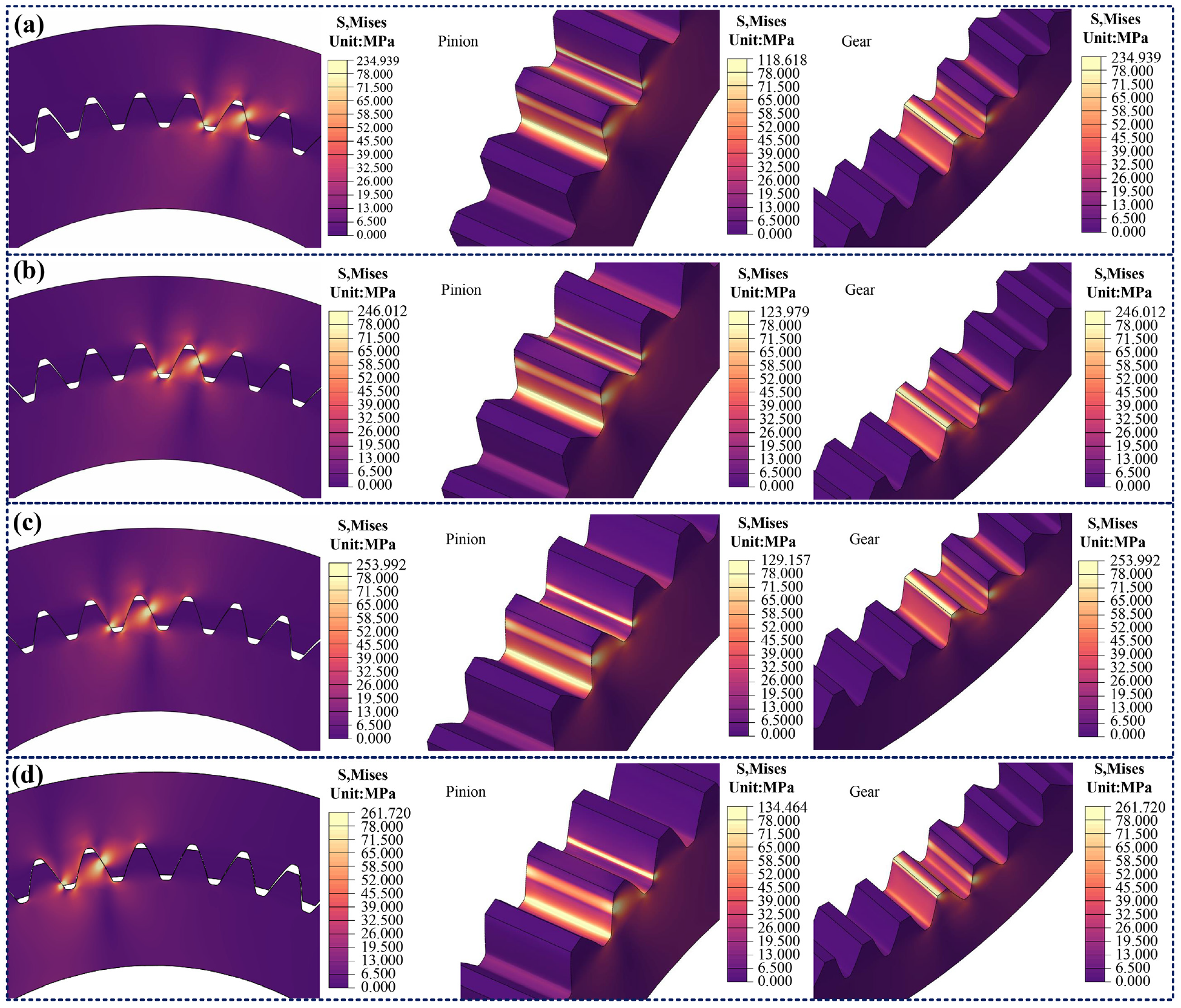
Contact stress distributions of ACG pair at different meshing positions: (a) frame = 15, (b) frame = 30, (c) frame = 45, and (d) frame = 60.
From the above discussion, we can conclude: (1) Under a given torque, adoption of the ACG tooth profile as the driving teeth can generate multi-teeth contact meshing in the reducer, thus improving its load carrying capacity and overload performance. (2) The linear contact form of the ACG pair is beneficial for torque transmission, which confirms that the ACG tooth profile is especially suitable for the transmission teeth of the ACG reducer.
Dynamic characteristic analysis of ACG reducer
The application of the ADAMS software to analyze the dynamic characteristics of the gear drive has become an important research direction in recent years.28,29 To verify the above design method of the ACG reducer, a virtual prototype model of the ACG reducer is established with the finite module of the ADAMS software and its dynamic characteristics are analyzed under the given drag torque (T = 100
The 3D model of the reducer is established in SOLIDWORKS, and the assembly interference analysis is also carried out. The model is saved as parasolid . x_t and then it is run in the ADAMS software. The simulation model adopts the case of fixed and internal gear ring output. Its main steps are as follows:
(1)
(2)
(3)
(4)
Condition of input shaft speed and load torque for ACG reducer.

Figure 8 shows the obtained angular velocity curves of the input shaft, adaptor and output shaft, and their theoretical values are also listed in Table 4. It can be seen that the output speed fluctuates between 1 and 1.5 rpm with an average value of about 1.249 rpm. The input speed is 114.7 rpm. According to the relationship between the input and output speeds, the actual transmission ratio of the ACG reducer is 91.83, and its relative error with respect to the theoretical value is 0.18%, which indicates that the ACG reducer model is established correctly. The speed of the adaptor is relatively stable, whose average value is 7.472 rpm and relative error with respect to the theoretical value is within 10%. It demonstrates the achievement of a modeling accuracy of this model.

Components of angular velocity of the ACG reducer: (a) input shaft, (b) adaptor, and (c) output shaft.
Parts of angular velocity of ACG reducer.

Simulation and calculated values need to be compared for checking the accuracy of the model. According to the operating principle of the ACG reducer, the meshing characteristics of the gear pairs in the first and second stages are similar, so we take the gear pair which consists of the second stage internal and external gear as the object here to study the contact force variation law during the gear meshing process. The contact force of the second stage gear pair of the ACG reducer was obtained by ADAMS simulation, as shown in Figure 9(a). When the speed of the reducer is stable, the contact force of the gear pair fluctuates slightly and changes periodically with an average value of 1936.02 N.

Comparison of contact forces of the second stage drive of ACG reducer: (a) results obtained using ADAMS and (b) results obtained using ABAQUS.
Similarly, the contact force of second stage gear pair of the ACG reducer, obtained by using ABAQUS, is as shown in Figure 9(b). Under the same torque, the contact force of the gear pair changes periodically with an average value of 1773.62 N. Compared with the results of the virtual prototype, the relative error of the average contact force (8.39%) of the gear is found to be below 10%, and the contact force of the two methods have the same value. It proves that the two methods of calculating the contact stress verify each other.
As mentioned above, the simulation of the reduction ratio is consistent with the numerical result, which depicts that the transmission scheme of the ACG reducer is correct. The proposed tooth profile helps in achieving smooth drive of the reducer. It can be concluded that the proposed ACG tooth profile is feasible as the ACG reducer drive teeth. Additionally, the virtual prototype model of the ACG reducer can provide technical support for tooth profile modification and experimental research in future.
Fabrication of ACG reducer prototype
In this section, we attempt to fabricate a prototype of the ACG reducer by applying the CNC processing technology. With the development of the CNC processing technology30,31 and equipment level, the machining of special tooth gears has become as simple and high-precision as that of ordinary gears. The ACG gear is a spur gear, which can be produced in large quantities using the machining technology of involute gear, such as milling, forming, and grinding. However, for small quantities of parts, the high-precision CNC slow-moving wire cutting technology can also be used to fabricate tooth profiles.
In considering accuracy and cost, the CNC slow-moving wire cutting processing (Chamir CUTE600) is selected for machining the tooth profile of the ACG pair, where the dimensional accuracy of the tooth profile reaches 0.005 mm. Upon polishing, the surface quality goes close to the grinding precision. The program of machining code is developed for generating the part of the reducer by using the DMU60 machining center and lathe (GS250plus). Each part of the ACG reducer is machined precisely according to the corresponding engineering drawing and the above machining technology. Finally, the physical prototype of the ACG reducer with a reduction ratio of 92 in Table 1 was successfully fabricated, as shown in Figure 10. The whole assembly process is noninterference type and meets the design requirements.

ACG reducer. Contact section of: (a) the first and (b) second stage of gear drives, (c) pin and adaptor, (d) the first and (e) second stage of reduction sections, and (f) assembled prototype.
Further studies on the transmission error, performance experiment, and structural optimization of the ACG reducer will be carried out. The excellent transmission performance of the proposed reducer is expected to be obtained on the basis of both theoretical and experimental investigations.
Conclusions
Due to various limitations on the structure, manufacturing accuracy and assembly of the traditional reducer, development of new reducer with high ratio, small volume and easy manufacturing is still needed. Therefore, a novel ACG reducer with a compound tooth profile of “epicycloid-involute hypocycloid” is introduced in this paper. The operating principle of the proposed reducer and mathematical model of the compound tooth profile are presented. The theoretical analysis and numerical calculation show that the ACG reducer has the advantages of compact structure, wide range of reduction ratio, and especially it can realize high ratio under the condition of non-small teeth difference, which makes it an alternative to the typical joint reducers used in industrial robots. Adopting the ACG tooth profile as the transmission tooth, the proposed reducer can generate multi-teeth mesh, thus improving its bearing capacity and transmission characteristics. The calculated and theoretical values of the reducer transmission ratio are consistent, which verifies the reasonableness of its structure and correctness of the virtual prototype. Finally, the prototype of the ACG reducer is successfully fabricated using the traditional machining technology.
Beyond the work in this paper, there are still some issues that deserve further research. In this paper, the obtained preliminary results show that the proposed ACG reducer is feasible and could have a promising application in future in the field of industrial robot joint reducer. In practice, there are many other parameters that can describe the transmission characteristics of the reducer, such as the transmission error, the transmission efficiency, and impact resistance. Future work can aim at experimenting and optimizing ACG reducer prototypes considering these performance parameters.
Footnotes
Appendix
μ dimensionless coefficient
Γ 1, Γ2 tooth profile of driving and driven gears
θ 1, θ2 actual rotation angles of driving and driven gears
ω 1, ω2 rotation speed of driving and driven gears
S f fixed coordinate system
S 1 coordinate system built on the driving gear
S 2 coordinate system built on the driven gear
n speed
Z i number of teeth
a center distance of ACG gear
r 1, r2 radius of pitch circle of driving and driven gears
M pitch point and reference point
i 12 transmission ratio
α transmission pressure angle
m modulus of gear
ha addendum height coefficient
c * dedendum height coefficient
T load torque of gear
J number of tooth differences of the first and second stages
G 1 tooth difference between the first stage internal and external gear
G 2 tooth difference between the second stage internal and external gear
Rd 1 center reference point of driving gear
Rd 2 center reference point of driven gear
Handling Editor: Chenhui Liang
Declaration of conflicting interests
The author(s) declared no potential conflicts of interest with respect to the research, authorship, and/or publication of this article.
Funding
The author(s) disclosed receipt of the following financial support for the research, authorship, and/or publication of this article: This research was supported by the National Natural Science Foundation of China [grant number 51975499, 52205055, and 51975500].
Data availability
The data used to support the findings of this study are available from the corresponding author upon request.