
Abstract
Installing robots in small businesses is primarily dependent on the ratio of money spent to achieve profit. In addition, from consumer pressure on the production, quality and low cost, the increasing cost of human labour leads to robot deployment. With falling prices of robots, their use is becoming increasingly common, which leads to small firms trying to implement robots that are not new. They try to buy a cheaper older robot or a robot that was damaged during its previous operation. It is necessary to eliminate the risk that arises from more serious damage to the robot, therefore, the requirements for verification of the robot’s resultant parameters after its repair performed in own interest. Based on such a requirement, the solution was to verify the parameters of the UR5 robot to confirm the possibility of its further use. After replacing the damaged parts, the robot was subjected to its parameter verification according to standard ISO 9283:2012. For measurement purposes, a measuring cube was designed and manufactured, as well as a measuring nest for Heidenhain sensors.
Introduction
Serial manipulators are used in many robotic systems. The serial robots are widely used in manufacturing, handling material and teleoperation. In the recent years, Universal robots (URs) have developed a series of robotic manipulators that are now widely used by many universities and industries. This robot is claimed to be fast, easy to program, flexible, safe and offers low-level programming access of the robot controller with high cycle time. Among the UR products the family of UR3, UR5 and UR10 have received a great attention within the robotics community and industries specifically by the robotic research community. 1
Collaborative robots are used today in different industries. Their deployment is based on the requirement to increase production efficiency without the use of closed robotic workplaces. If it is not necessary to separate the robot from a human in terms of safety, it is possible to save on the desktop and on input costs. Collaborative robots are becoming part of the production company and due to their low demands on space, safety and easy installation. Without additional investment, they can be integrated into existing production lines and thus easily replace human labour. Collaborative robots are particularly suitable where robot arm cooperation with man is required, we do not require high speeds and we have limited space to install the robotic workplace. 2,3
The number of robots deployed from the UR in industry exceeded 10,000 units in 2016. They are deployed in various industries, and especially in an environment, where cooperate with human. The manufacturer states that the average return on investment from the robot purchase will return within 195 days. In the Central European countries, the precondition of return investment is up to 1 year. The UR5 type is particularly suited for the automation of production processes of various parts of a lower weight at a working range of 850 mm. In terms of service requirements and programming, UR robots are the most intuitive on the market. Basic parameters of the UR5 robot (production year 2016) are presented in Table 1. 4
Basic robot parameters.

This study seeks to advance technologies pertaining to the integration of low-cost collaborative robots to perform a variety of operations where moderate accuracy is needed. 5
The verified UR5 robot was damaged when a part of the load was dropped, from a crane running over a robotic cell. In the robotic cell, there was a second UR5 robot, which was damaged even more, so he served as the donor of the necessary components. The damage was mainly related to the third and fourth joints, the damaged parts were replaced by the undamaged second robot parts. Repairs of damaged parts were carried out by the maintenance staff of the company in which the robot was damaged. The change was performed without the support of the robot manufacturer or vendor. After completing the change of damaged parts, the robot was tested, showing no signs of damage. As the company does not have the appropriate measuring technique and methodology, the staff of the Technical University in Kosice, Department of Robotics was asked to verify the parameters. Figure 1 is a three-dimensional view of the UR5 robot with components that have been changed.

Forces (F) and moments (M) on the collaborative robot.
The UR5 robot under investigation was manufactured in 2016 when ISO TS 15066-2016 was still being developed.
It meets the requirements of ISO EN ISO 10218-1: 2011 and ISO EN 10218-2: 2011, since the manufacturer of the ‘UR – Universal Robots’ has used them to design the robot. Testing of the robot according to the mentioned standards was not carried out.
Currently, the robot works in a closed cell, without access by the operating personnel. The reason is the need to ensure the least dustiness when handling (inserting parts) into prescribed positions. The robot is involved in the production of ‘high precision reduction gear’, where it works as a standard industrial robot, so the risk of human contact is minimal.
Selection of required measurement tests
One of the main characteristics of industrial robots is their positioning accuracy, strongly depending on the sensor resolution and the geometric parameters. 6,7
Based on customer requirements and the type of damage to the verified robot, measurement tests have been proposed, based on standard ISO 9283. 8 Tests have been selected from the above standards, the implementation of which ensures the identification and comparison of the required characteristics. The baseline conditions must be met before the measurement itself. The robot must be fully assembled and fully functional. 9
Before the test, the movements of the robot must be limited as necessary to set-up the measuring instruments. The test must be preceded by the designated warm-up operation if specified by the manufacturer. The ambient temperature in the tests should be kept within 20 ± 2°C. Measured location and orientation data (coordinates xj , yj , zj , aj , bj and cj ) must be expressed in a coordinate system whose axes are parallel to the axes of the coordinate system of the base of the measured robot. 10,11
The values of position repeatability (RP) and static compliance (SC) of the robot were selected as the most important verification parameters. The reason was the need for a finding or the robot is able to continue working on the required manipulation role while ensuring sufficient movement speed and accuracy of storage. 12 Selected tests with definition of load, output speed of rotation and number of cycles are presented in Table 2.
Selected tests according to standard ISO 9283.

RP: pose repeatability; SC: static compliance (RP).
The following requirements must be met for the placement of the measuring cube in the robot workspace: Five points (P1 to P5) are located on the diagonals of the selected plane. These five points, along with the manufacturer’s guideline, form test positions. The test positions must be defined by the coordinates of the base. Point P1 is the diagonal intersection and is the centre of the cube. Points P2 to P5 are spaced from the diagonal ends 10 ± 2% of the diagonal length. If this is not possible, the nearest diagonal point must be selected. All robot joints must be applied while moving between all test positions. 13,14 The location of the measuring points on the measuring cube is shown in Figure 2.

Measuring cube.
The location of the measuring cube in the robot workspace is shown in Figure 3. The maximum dimensions of the measuring cube are 500 × 500 × 500 mm3.

The location of the measuring cube in the robot workspace.
One-way position repeatability (PR) and static compliance (SC)
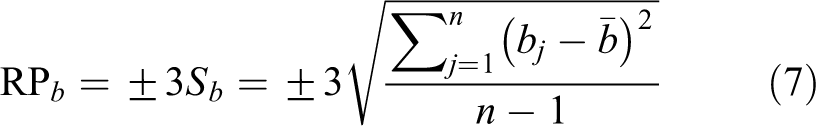
One-way repeatability measurement is performed by running the end part of the robot mounted with the measuring cube to the measuring place (measuring node) and subtracting the measured values on the system of the six sensors. Position repeatability (RP) indicates the degree of match between placements and orientation of the positions achieved after n-repetitions of move to the same programmed position in the same direction. For a given position, it represents the RP value, which is the radius of the sphere whose centre is the barycentre and which is calculated as the scatter of angles 3Sa
, 3Sb
and 3Sc
around the mean values

where

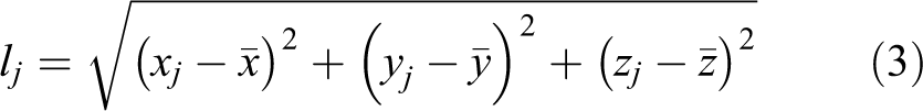

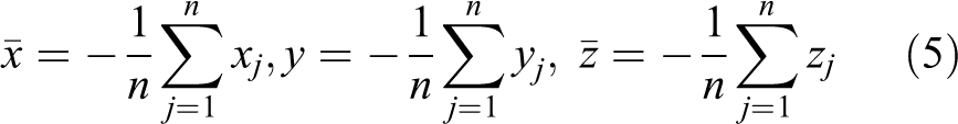
where xj , yj and zj are actual (measured) values. The coordinates of the barycentre of the achieved points at n-repetitions of the same position are calculated according to the relations
Scatter of angles 3Sa
, 3Sb
and 3Sc
around the mean values


When measuring SC/stiffness, the robot and the robot control system are on but the robot does not move. The forces used in the tests must be applied across the gravity centre of the instrument in three directions, both positive and negative, parallel to the axes of the coordinate system of the base. The forces must increase gradually from 10% to 100% of the nominal load, one way at a time. For each force and direction, the corresponding displacement is measured. This test is done with centre of the mechanical connection (interface) located at point P1.
Mathematical background of UR5
Stiffness analysis
Mechanical stiffness of the industrial robots is one of the important features for designing and analysing. In general, the development of stiffness matrix of robot serves to define positioning errors while external forces/torques affect the robot. In other words, stiffness matrix expresses resistance of the robot to deformations due to external load. For example, elastokinematical models of manipulators are developed in 17 or. 18 Stiffness analysis allows designers and engineers to achieve the balance between dynamics and accuracy. 19
Nowadays, there are three basic methods dealing with the mentioned investigated issue, namely finite element analysis, matrix structural analysis and virtual joint modelling (VJM). This article deals with VJM method, which is based on a rigid body model by adding virtual joints. Virtual joints, imaginary springs, describe elastic deformations of links. One of the first works in this area was the work of Salisbury. 20
Assuming that joints friction forces are negligible we can derive the following formula for stiffness analysis. Considering that

where

where

Based on previous researches the model for stiffness matrix can be written as

where

Mentioned terms will be now used for the analysis of UR5 stiffness and theoretical end-effector position deflection. Example of simulations is shown in Figure 4, in Matlab R2018b. Simulations were done with constant z-axis with changing end-effector position in x–y plane. The end-effector drown the circle in the x–y plane.
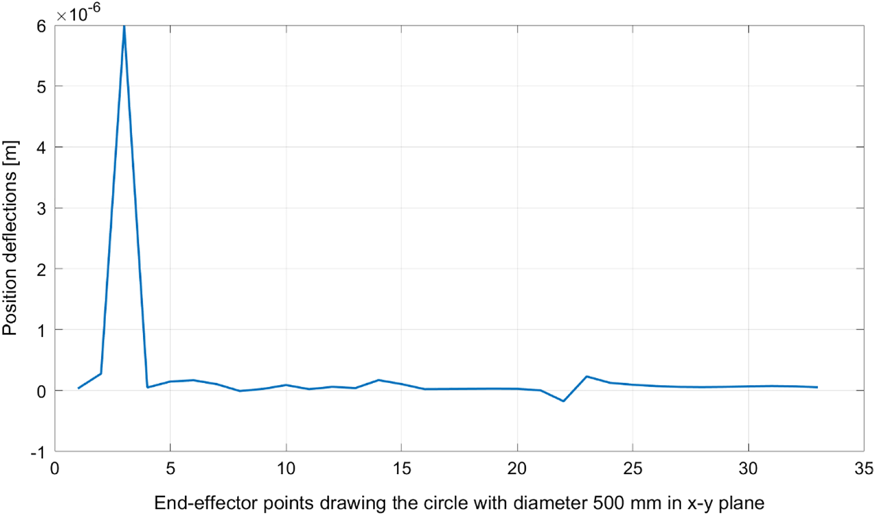
Deflection of end-effector.
Dynamic model of UR5
Generally, there are two basic issues for dynamic modelling, namely forward dynamics which computes the joint acceleration and consequently other kinematic variables while the vector of generalized forces/torques is given. On the other hand, inverse dynamics deals with the computing of forces/torques while the kinematic variables are known.
Euler–Lagrange method was used for the dynamic model within this study. This method is based on the basic term

where ψi
represents extern and dissipative generalized forces and

Potential energy is

where

What can be expressed by generalized form

where M is a matrix of inertia
Results and discussion
To verify the parameters of the UR5 robot, it was necessary to create a suitable measuring nest. The nest was able to verify the resulting values, in particular, the accuracy of the robot output flange. Two types of measuring instrument were considered for measuring. The first type consisted of a measuring sphere, where measurement would be carried out by a set of three perpendicularly stored sensors (measuring SC). The second type consisted of the use of a measuring cube where measurement in three perpendicular axes would be carried out using a set of six sensors (pose repeatability). Figure 5 shows a view of the storage of six sensors and a measuring cube.

Location of sensors and measurement cube.
In order to accurately place the measuring sensors together, it was necessary to design the measuring nest, allowing their rigid clamping. The diameter of the measuring sphere is Ø 60 mm, and the size of the measuring cube is 60 × 60 × 60 mm3. Two types of sensors were selected for measurement, namely, MT12 and MT25. 22 The clamping diameter of their contacts is Ø 8 mm in diameter. On the basis of this information, it was possible to design the internal dimensions of the measuring nest 90 × 90 × 90 mm3. The measuring nest is assembled from three side walls into which it is possible to fasten the sensors using suitable enclosures. The fourth wall serves to secure the nest in the robot workspace. Figure 6 is a view of a measuring nest in which two and six sensors are located.

Measuring nest.
To ensure the proposed measurement, the appropriate weight must be placed on the robot flange. The load value will represent the load on the robot at 10%, 50% and 100% of its nominal capacity. The placement of the weight is located in the last rotation axis of the robot. The overall view of the positioning of the UR5 robot on the measuring station as well as the location of the measuring nest and sensors is shown in Figure 7.
Measuring station.
Discussion
All the measured data from the respective imaging units were automatically recorded using the camera (jpg) in the computer memory (Figure 8). Subsequently, the data were transferred to the appropriate measurement protocols.

A photo of the measured data recorded in the computer’s memory.
One-way RP
In the test were realized a total of 30 measurements at 5 measuring points (P1, P2, P3, P4 and P5), 2 load combinations (100% and 50%) and 3 combinations of speed motion (100%, 50% and 10%). In Table 3, the calculated values for point P1 to P5 are displayed. The table contains only the results of protocols no. 1, 7, 13, 19 and 25, wherein results of the complete 30 protocols are shown in Figures 9 and 10.
Values (RP) in point P1 to P5 (mm).

RP: pose repeatability.

One-way pose repeatability (RPa, RPb and RPc) of robot UR5.

One-way pose repeatability of UR5.
Figure 9 shows the progress of calculated one-way pose repeatability values (RP a , RP b and RP c ) in two perpendicular directions at two load values, three velocity values and five measurement points. Since the computed data are compared with each other under different conditions (load, speed and position in space), this graph has an informative function.
Figure 10 shows the progress of the calculated one-way RP values in three perpendicular directions at two load values, three speed values and in the five measurement points. Since the computed data were compared with each other under different conditions (load, speed and position in workspace), this graph has an informative function. On the horizontal axis of the graph, the maximum measured values in the relevant measurement protocols are shown.
The UR5 robot catalogue data is the one-way pose repeatability value (± 0.1 mm). Since none of the measured values exceeded the prescribed value, we can state that the robot is ACCEPTABLE.
Static compliance (SC)
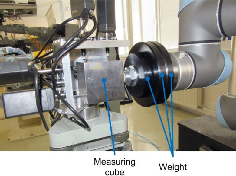
Measurement is performed by adjusting the end part of the robot with the installed measuring ball (sphere) to the measuring point P1. The reading of the measured values is carried out on a set of three sensors, with the gradual loading of the robot flange. The measurement direction is in the (+/−) ‘X, Y, Z’-axis. The measurement is performed by repeating the test cycle three times for each direction. Figure 11 is a view of the measuring ball and weights positioned to act on the robot end flange in two perpendicular directions. The left part of the figure shows a view of the placed weights acting on the robot via the pulley system in two axes. The middle part of the picture shows a closer view of the use of the weight and at the same time the view of the measuring nest where the measuring ball is located. The right part of the picture shows the detail of the measuring ball with the location of the measuring contacts.

Measurement of SC.
The calculated values of the SC of the UR5 robot based on the 54 values measured are presented in Tables 4 to 6.
SC in the X-axis direction.
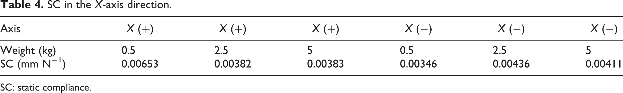
SC: static compliance.
SC in the Y-axis direction.

SC: static compliance.
SC in the Z-axis direction.

SC: static compliance.
Since the manufacturer does not mention the value of this parameter in its technical documentation, the test result is only stated. After making the same measurement on another (undamaged) robot UR5, deviations of maximum +/− 5% were found. Therefore, it is possible to declare that the repaired robot is suitable for production operations, where the repeatability accuracy of the manipulation does not exceed 0.1 mm.
Conclusions
The deployment of repaired robots to various areas of industry in Slovakia and Central Europe has an increasing tendency. Over the past 3 years, the authors of this article have been approached at least eight times with the requirement to deploy such a robot. The use of a repaired robot in Slovakia reduces the cost of its purchase by 20%–40%. At present, we are checking the parameters of another repaired Kuka KR 6 robot, which was produced in 2016.
Based on the verification carried out on the robot UR 5, according to standard ISO 9283, it was measured and calculated that the robot meets the requirements for its reuse. The calculated ‘one-way RP’ values at any measured point did not exceed the manufacturer’s reported 0.1 mm.
Only two test results are presented in the article, but the following tests according to standard ISO 9283 have been implemented for the customer’s needs: ‘Pose accuracy (AP)’, ‘Drift of pose accuracy (dAP)’ and ‘Drift of pose repeatability (dRP)’.
Footnotes
Acknowledgement
The authors would like to thank Slovak Grant Agency – project VEGA 1/0389/18 – Research on cinematically redundant mechanisms and VEGA 1/0872/16 – Research of synthetic and biologically inspired locomotion of mechatronic systems in rugged terrain.
Declaration of conflicting interests
The author(s) declared no potential conflicts of interest with respect to the research, authorship, and/or publication of this article.
Funding
The author(s) received no financial support for the research, authorship, and/or publication of this article.