
Abstract
This article presents a design of novel wheelchair with a leg exoskeleton for locomotion that can be powered by user legs through a cycling action. In addition, the control system is designed with leg-motion assistance for lower limb muscles to perform exercise during wheelchair motion, targeting elderly persons and users with partial hemiplegia. The simulation results characterize the dynamic operation in three possible modes, fully active, fully passive, and user passive–active action.
Introduction
The increasing number of elderly people, stroke-sufferers, and spinal cord injured ones in modern society has introduced unavoidable geriatric disorders, physical disabilities, and locomotion challenges, such as full or partial loss of hip, knee, and ankle function. These conditions adversely affect the execution of daily activities, and in severe situations, they can even result in hemiplegic paralysis diseases. 1 Clinical medicine indicates that persons suffering from partial hemiplegia that is caused by muscle weakness require daily exercise to effectively work in physical rehabilitation. When this is ignored (i.e. there is a lack of regular exercise), the lower limbs may suffer complete hemiplegia. 2,3 Thus, it is crucial for partial hemiplegia persons to receive rehabilitation and mobility assistance in the context of daily life. The proposed wheelchair with lower limb exoskeletons offers one such a promising solution.
The wheelchair is indispensable to elderly or infirm patients, especially for those with lower limb hemiplegia at all severity levels. There are many types of wheelchairs available in current market. However, the majority of these machines are used for traveling short distances, with hand-powered movement and control like those reported in the study by Karmarkar et al. 4 and Berkelmans et al. 5 In general, such a traditional design is convenient for user-based operation with basic features. This kind of wheelchair is even suitable for some patients with lower limb amputation. However, with the ongoing achievements of modern technology in mainstream societies, patients with physical disabilities can further achieve independence through locomotion aids and living-assistance tools. For example, patients may not only require easy-controlled wheelchairs, but they may also want to improve daily routines, general health, and even engage in physical recovery during assisted movement.
In recent years, several multifunctional wheelchairs have been developed and some electric-powered wheelchairs work saving the user from expending significant amounts of energy in order to move. In 1996, Yoder et al. developed an auto-guide-powered wheelchair for individuals with severe disabilities that used an accurate estimation of the wheelchair location in the context of its operating workspace as the basis of its control. 6 In 1998, Bourhis et al. proposed a man–machine cooperation with the control of an intelligent-powered wheelchair that is described as a mobile robot facilitating task and information sharing between man and machine. 7 In 2002, Cooper et al. developed a comparison for a virtual and an actual electric-powered wheelchair control using a position-sensing joystick and an isometric joystick. 8 Moon et al. proposed the control of a wheelchair using EMG signals, with a further integration of user and wheelchair that involved bionics. 9 The Ottobock Company has applied for numerous patents for different kinds of wheelchairs. 10 Even though the abovementioned wheelchair designs have become increasingly intelligent and more human-oriented over the course of their developments, nevertheless, they cannot offer the possibility of exercise to the users. In some cases, they might inadvertently contribute to muscle atrophy, and therefore, they can be adverse to the health of the user.
Leg pedaling exercises, such as cycling, are widely accepted as a therapeutic modality for stroke and spinal cord injured patients because they increase muscle strength and endurance. 11 Several studies have focused on the clinical efficacy of cycling exercises for the improvement of leg muscle function and coordination, finding that the cycling motion is an effective rehabilitation exercise. 12,13 In particular, Handa et al. developed the Profhand wheelchair, which helps motor function rehabilitation of the lower limbs using pedal cycling. 14 –16 This wheelchair is propelled by the lower limbs of a user in a way that can be compared to the upper limb propulsion of a conventional wheelchair. Thus, this is a novel approach to enabling daily activities, thereby promoting exercise of the lower limbs. However, it might not be sufficiently safe for users with severe illnesses, for example, when the patient’s lower limbs are numb and the patient cannot control his legs precisely, the legs maybe sway from side to side, and this leg motion can be dangerous. In addition, some users may not be strong enough to drive the wheelchair. Borisoff et al. proposed a concept that combines the characteristics of the wheelchair with an exoskeleton using the wheelchair for the movement and the exoskeleton for the rehabilitation. 17 The exoskeleton design has become a research hot spot with solutions that now provide specific advantages in strength enhancement 18,19 and rehabilitation tasks 20 –23 for humans. For example, the Honda exoskeleton was designed to support the wearer’s body weight, which reduces strain on the articulations in the knees, ankles, and hips. 24 At the Laboratory of Robotics and Mechatronics in Cassino (Italy), a low-cost easy-operated leg exoskeleton was developed with a cam-mechanism implementation at the ankle joint, which assists the load-carrying motion of the leg. 25,26 The active leg exoskeleton was proposed by the Mechanical Systems Laboratory, at the University of Delaware (USA), as a human–machine-based interface for gait rehabilitation of patients with walking disabilities. 27 The abovementioned rehabilitation exoskeletons actually work most of the walking movements for the user, which may be difficult or even dangerous for some seriously infirm persons. At present, it seems there is no solution that can simultaneously fulfill rehabilitation for the lower limbs and mobility requirements.
The characteristics of leg exoskeletons can be conveniently combined with the design of a new wheelchair. This article proposes a new solution for a wheelchair with leg exoskeletons for daily movement and assisted exercising. This design is considered to be an optimal way to fulfill user needs for regular movement and intentional exercise. The aim of the design is to ensure that locomotion and rehabilitation goals are combined with the functions of the wheelchair and exoskeleton. A computer aided design (CAD) design illustrates the proposed wheelchair together with results of a dynamic simulation proving its feasibility.
The rest of the article is organized as follows. Firstly, cycling motion characteristics and their beneficial relevance to wheelchairs are introduced. Next, leg exoskeleton-assisted wheelchairs are specifically examined, so that a dynamic simulation with CAD models can be used to determine performance characteristics. The results of the simulation prove the soundness of the proposed design. Finally, the results are discussed, so that future-related work can be indicated.
Human cycling motion in cycle-assisted wheelchairs
Cycling is a recreational activity that has achieved worldwide participation, with the sport of cycling growing in popularity for its health benefits. The benefits of cycling are identified as follows. Firstly, cycling is widely used as an effective and efficient mode of transportation for short to moderate distances. 28,29 Secondly, cycling provides sustained physical exercise that incorporates the coordination of muscle movement for the entire body. In general, the cycling motion action is a repeated motion that can also be used for rehabilitation exercises in terms both of quality and quantity (for exerted motion). The primary aim of this article is to determine an optimal cycling wheelchair design. According to the research of Gonzalez et al., 30 there are five variables that affect cycling motion: pedaling rate, crank arm length, seat tube angle, seat height, and longitudinal foot position on the pedal. A sensitivity analysis of each of the five variables shows that the order of importance for the variables is pedaling rate, crank arm length, seat tube angle, seat height, and longitudinal foot position on the pedal. In addition, the knee and hip joint angles throughout the cycling motion also have a significant influence because of the different forces acting in the joints. When the maximal knee joint angle reaches 130°, a comfortable posture is achieved for strong riding. 31 The above conditions also make the design of a wheelchair as multipurposed problems, that is, transport and exercise.
In cycling-assisted wheelchairs, the action of a user can be transferred or received through the crank cycle as part of the cycling operation. Here, the crank cycle is separated into three phases 32 : propulsive-power down stroke, pulling-recovery upstroke, and pushing phase, in which the foot is pushed forward to the top dead center (TDC). The propulsive-power down stroke phase relates to the powering action of the leg to drive the bicycle forward. The pulling-recovery upstroke phase is the next motion with no powering action. In addition, the pushing phase represents the short transitory stage between the two abovementioned phases. During this phase, the two legs gradually change their action. There is a kind of rest during the pulling-recovery phase. When a proper motion/power ratio transmission is implemented, the characteristics of these three cycling phases can be used to inform the design of a mechanical system driven by a human with lower limb debilities. Hence, the aim is to model a wheelchair that uses the cycling action for propulsion irrespective of the physical condition of the user.
In the seated position in the wheelchair, cycling can also function as an exercise source for the leg muscles. In order to exercise as many muscles as possible, the crank length and seat height should be treated as a function of user size and capability. In terms of efficiency, there should be a smooth transition from the power to recovery phase during the motion across the bottom dead center (BDC) and pushing phase across the TDC.
In order to fulfill user movement and rehabilitation needs, a new wheelchair design should incorporate a leg exoskeleton that assists guidance and leg motion, so that it could also be suitable for user needs relating to rehabilitation. Although this would include users with hemiplegic paralysis, stroke limitations, and accident-based injuries, the proposed exoskeleton-assisted wheelchair would also be suitable to the elderly people for transport and exercise.
Kinematic design of leg exoskeleton cycling-assisted wheelchair
After reviewing the cycling possibilities for a wheelchair, a new kinematic design is proposed that combines an adaptation of a traditional wheelchair with the leg exoskeletons to assist leg cycling.
In order to design an easy-operated wheelchair, user requirements are considered. Firstly, a wheelchair can be fully customized to suit a specific user, that is, it can be size-adjusted to fit the anatomy of the user. Also, a comfortable exoskeleton can be arranged for users in the seated position. After considering the different physical conditions of various users in different rehabilitation phases, a slave–master solution is proposed for the wheelchair control as in Figure 1. Here, the motions of the wheelchair and the user legs are activated by the patient either through the strength of the user or by the master motors that are fixed on the exoskeleton. In the case of a leg-powered exoskeleton, the wheelchair obtains input power from the slave motor via crank pedal motion, which is assisted by the master motor on the exoskeleton to promote active rehabilitation or exercise of the user’s legs (Figure 1). Elsewhere, the wheelchair is powered by the slave motor that inputs motion to the legs through the crank pedal with the exoskeleton master motor assisting leg action in passive rehabilitation exercise. Furthermore, it is possible to have a combination of the abovementioned operation modes with a partial action by the user’s legs.

Scheme for slave–master actuation in proposed leg exoskeleton cycling-assisted wheelchair.
Figure 2 shows the design procedure for the new wheelchair. Here, the user’s needs and capabilities are considered in order to efficiently operate the leg exoskeletons for both wheelchair locomotion and rehabilitation exercise.

Flowchart summarizing proposed procedure for designing leg exoskeleton-assisted wheelchair operation.
The “patient action” box represents the start of the operation for the leg exoskeleton wheelchair. It is activated by the user through sensor signals that are used to directly feel leg actions through commands by the control unit at hand. The interrogative box “motion intention” refers to sensors that can detect the intention of the user to move and work in rehabilitation exercise. The “Yes” condition brings to “power from leg exoskeleton” box, indicating that the wheelchair motion is driven by the leg exoskeleton. The “No” condition brings to “power from master motor” box, showing that the user does not propel the wheelchair, but the power for the wheelchair motion comes from the activated master motor.
Wheelchair movement simultaneously engages the patient legs in exercise, as indicated in the flowchart box coming to “motion of patient legs.” The interrogative box “exercising leg exoskeleton” is another important target because it can indicate that the user’s legs are engaged in exercise during wheelchair movement. The “Yes” condition brings to “leg efforts” box, which indicates that the motion of the exoskeleton is powered by the user. In this case, the legs exert the total power to drive the exoskeleton and wheelchair, as indicated in the box “fully leg active action mode.” In the case of power from limbs, the hip actuator can be deactivated, thanks to a signal from the force sensor on the pedal giving indication of limb power and user’s intension to move the cycling by legs only. This is the fully active mode of leg action referring to Figure 2 for the situation in which hip actuators do not work and the active force for moving lower limbs is provided by the legs themselves. Alternatively, the “No” condition brings to “legs are guided by slave motor” box, which indicates that the leg exoskeleton drives the legs as indicated in the “fully leg passive action mode” box. In addition, when the patient has insufficient strength for wheelchair and exoskeleton actuation, the intermediate state of “passive–active mode” is activated with the simultaneous action of the user’s legs and motors.
The proposed procedure gives general instructions for the design of a user-oriented easy-to-operate wheelchair system that can be propelled while simultaneously exercising the legs. In addition, the master–slave method can fulfill the needs of users by offering different action modes in Figure 2.
A new wheelchair is designed with the inclusion of leg exoskeletons using the described procedures in Figure 2. Figure 3 shows a kinematic sketch of the wheelchair with leg exoskeletons in which a four-bar linkage is used as the basic mechanism for the exoskeleton in order to ensure a simple and reliable mechanical design (also assisted by the crank-rocker mechanism). In Figure 3, the terms θ 2, θ 3, θ 4, θp , θw , and θsw refer to the angles of the hip, knee, ankle, crank, back wheel, and front wheel, respectively, which are parameters for the wheelchair motion; L 1 is the distance between the axes of front wheel and rear wheels; L 2 and L 3 are the exoskeleton length of the thigh and shank, respectively; Lp is the crank length; and vectors R2, R3, and R4 refer to the reaction forces of the hip, knee, and ankle joint, respectively.

A kinematic sketch of proposed leg exoskeleton-assisted wheelchair system with its main design parameters.
The length of the rocker and other linkages are designed with sizes that can be customized for the length of the shank and user thigh (Figure 3). They can be adjusted for adaption to a broad range of human physical dimensions. The parameters of L 1, L 2, L 3, Lp , θ 2, θ 3, and θ 4 not only satisfy the movement principle of the crank rocker, but they can also be properly sized for the majority of people within the normal size range. In addition, the crank length and wheelchair height have been carefully designed to accommodate typical situations, with ranges for θ 2, θ 3, and θ 4 that accommodate user exercise needs. In particular, θw of the rear wheel axis can be calculated as

where θw is given by the slave motor in the locomotion mode imposing the leg motion through θp ; θw can also be given by θp because of the active motion of the leg under the help of the exoskeleton through the master motor motion; otherwise, θw is obtained by a simultaneous action of the two motors. θp can be expressed by the kinematics of a four-bar linkage (Figure 3) in the formula
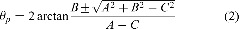
where
The reaction forces at the hip, knee, and ankle joints can be expressed as

where u is the parameter modeling properties in the joints when related to the stiffness and the damping. In the proposed design, aluminum alloy is chosen for the link structures in the exoskeleton linkage.
Mechanical wheelchair design
The proposed elaborate mechanical design works with a motor at the exoskeleton joint, which helps a user partially or fully power leg exercise and wheelchair motion. A simplified mechanical design solution avoids the slave motor altogether using a transmission chain directly connecting the crank pedal to the rear wheel axis. Having the motor with motor reducer in the hip position can simplify the mechanisms at pedal place, since it is important to make it easy for users to stand up and sit down from the wheelchairs. In addition, it is a safety consideration to put the motor with motor reducer in the hip position. Although the motors would need a high transmission ratio at that place, users need less force to stop the motor rotation when compared with the solution having motor fixed in the pedal place in the case the motor is out of control. Figure 4 shows a detailed CAD design for this solution. Based on the flowchart of the proposed procedure in Figure 2 and the kinematic sketch of the exoskeleton, wheelchair system is designed in Figure 3 for a user-oriented easy-to-operate wheelchair with leg exoskeleton. Figure 4 shows the main components and general configuration in a CAD-based mechanical design.

A CAD model of the proposed design in Figure 3.
The CAD design of the new wheelchair with leg exoskeleton mechanisms is characterized by three parts, namely, wheelchair frame, leg exoskeletons, and transmission system. Three wheels are connected to the wheelchair frame, with the front one that is used for guiding the direction of the wheelchair motion by means of a cable lever to the user’s hand. Each leg exoskeleton (with three joints) is connected to the wheelchair frame by a motor and clutch, which is connected to the crank pedal. The transmission system includes two pulleys and one belt which connects the axis of the pedal crank to the rear wheel axis. The speed of the wheelchair can be controlled in two ways. When the movement of wheelchair is actuated by a motor, the servomotor can control the speed, and if the speed is too fast, the brake installed in the left handrail (as shown in Figure 4), which is controlled by the user’s hand, can also be used to control the speed.
The servomotor has a clutch with two options that is connected to hip joint of exoskeletons. When the switch turns to the left, the motor is actuated, and the exoskeletons and wheelchair are driven by servomotor. When the switch turns to the right, the motor is disabled, and the exoskeletons can be moved freely. In that case, since the transmission between the pedal and wheelchair’s back wheel is unidirectional (like in bicycles), a user would have the options to only move the wheelchair by other person’s help or by the action on the pedals.
In general, one actuator for driving the rocker cannot ensure the continuous cycling motion task without the help of inertia. But the reasons for which the proposed crank rocker mechanism can solve the TDC and BDC position problem are as follows. On one hand, when one user is seated in the wheelchair, user’s legs have weight, whose inertia can enable the mechanism to pass the dead center positions. In addition, the position of dead point in the designed mechanism is not a balance position because of the weight of crank and pedal, so that the crank will not stop at the dead point position and therefore can avoid the mechanism starting to rotate at the dead point position. Consequently, whether at the beginning of the cycling motion, or during running, the mechanism can work the cycling task with one actuator and with the help of users.
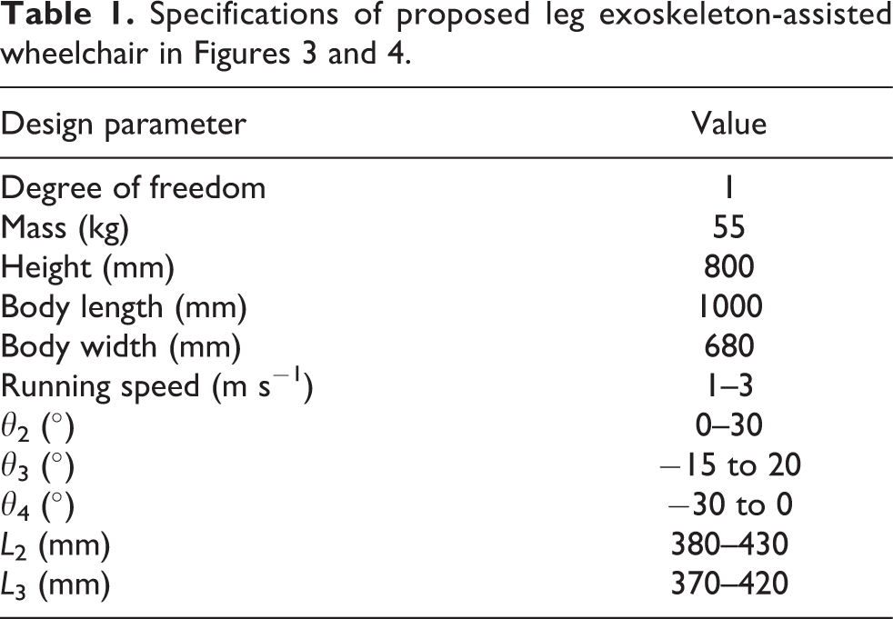
Based on the previous research, 21,33,34 the design and operational requirements of the proposed wheelchair with leg exoskeleton are informed by the user profile of an elderly man or stroke patient with hemiplegia. Table 1 lists the main parameters of the wheelchair and leg exoskeletons with the characteristic values for the proposed solution. The angle of each joint is carefully sized for user motion needs and exercise requirements. The lengths of L 2 and L 3 are designed for users within the typical adjustment size range. In particular, only one motor for each leg exoskeleton is used for the motion of leg exercise that is assisted by the exoskeleton. The design parameters of the proposed wheelchair mass, height, body length, body width cover, wheelchair frame, and size are designed for a standard home environment using data from traditional wheelchairs. The average running speed is assumed as 1.5 m s−1, which is an acceptable value for a traditionally powered wheelchair. 35 Although this value is fixed for the simulation, it can be conveniently adjusted by controlling the motor according to the user needs in an actual environment. The transmission ratio between the transmission pulleys is 3:2 for the CAD solution in Figure 4, but it can also be adjusted as required in actual situations by different transmission pulleys.
Modeling and simulation results
Based on the mechanical design in Figure 4, a simulation model was built in an ADAMS environment as in Figure 5. The model shows all the revolute joints and axes for the dynamic simulation in order to explain the simulation outcomes. The body structure of a user was simplified using volumes with weights properly considered in the model yet. In the simulation, the leg exoskeletons and human legs were fixed together in order to simulate a totally passive motion mode.

An ADAMS model based on the mechanical design with listed parameters in Table 2.
Table 2 summarizes the data and parameters that were assumed for the simulated operation of the model in Figure 5. A belt transmission with a transmission ratio of 1:1 was chosen, and all revolute joints in the model were defined by taking into account the friction as reported in Table 2. Contact between the rear wheels and ground was carefully modeled by assuming values as in Table 2 to reflect a realistic situation.
Simulation parameters for wheelchair operation in ADAMS environment.

The cycling motion of the crank is cycle and repeatable, so that the interval time of two cycles is used to describe the characteristics of the system to show the continuous operation. The simulated operation was obtained by applying input motion at the crank pedal with a constant speed of 30 r/min−1. The simulation ran for 20 s, with the period from 14 s to 18 s selected for the reported discussion. A complete rotation takes 2 s, and hence, two rotations occurred for the selected simulated results. The rotation times were selected as characteristic of general functioning. Figure 6 shows a snapshot of the simulation results for a characteristic cycle. It outlines the crank motion (yellow) according to the three crank cycle phases that occurs during the cycling action for the cycling rotation of 4 s. Figure 6 also shows the reaction forces and torques of the revolute joints (red arrows).

Snapshots of simulated motion of ADAMS model with indication forces and torques during one full cycling rotation at (a) 0 s, (b) 1 s, (c) 2 s, and (d) 4 s.
Figures 7 to 12 show the numerical results of the simulation for the two abovementioned rotations during the lower limb cycling motion.
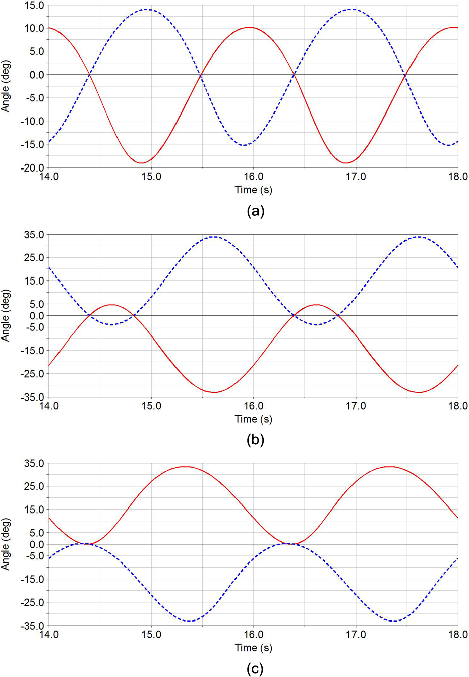
Computed angles of left and right legs for simulated motion with active exoskeleton at (a) hip, (b) knee, and (c) ankle. (Left and right feet are represented by continuous and dotted lines, respectively).

Computed angular velocities of left and right legs during simulated motion with active exoskeleton at (a) hip, (b) knee, and (c) ankle. (Left and right feet are represented by continuous and dotted lines, respectively).

Computed magnitude of joint reaction forces at left and right legs with active exoskeleton during simulated motion at (a) hip, (b) knee, and (c) ankle. (Left and right feet are represented by continuous and dotted lines, respectively).

Computed reaction forces of simulated motion of wheelchair with active exoskeleton at (a) back wheels, (b) front wheel, and (c) crank pedal.

Computed torque at crank pedal for simulated motion of wheelchair with active exoskeleton.
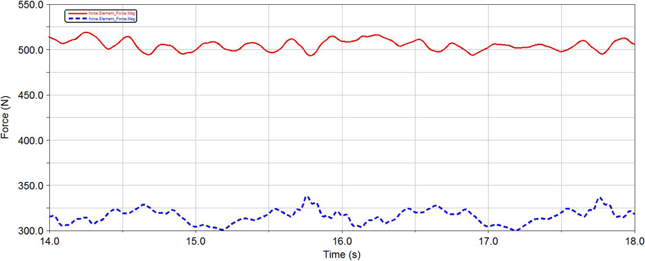
Computed contact forces of simulated motion between wheelchair rear wheel and ground. (Front and rear wheels are represented by continuous and dotted lines, respectively).
Figure 7 shows the computed results for joint angles in the legs in the form of plots for hip, knee, and ankle joints. In particular, cycling characteristics were given by input motion via a sinusoidal motion of the crank pedal. Figure 7(a) shows the hip angular motion with a periodical evolution, like a trigonometric function with smooth behavior. The computed angular range for the hip joints is 30°, which can be considered reasonable for a typical user even in rehabilitation therapy situations. Figure 7(b) shows the knee angular motion results with an interval ranging from −4° to 33° in the right knee, which is also reasonable for a typical user even in rehabilitation therapy situations. In addition, for the ankle angular joints in Figure 7(c), the computed amplitude is approximately 35° for the left leg, ranging from 0° and 35°. This is due to an ankle motion, where the user experiences no particular stress during the exercises when using the cycling motion of the wheelchair.
Figure 8 shows that the maximum angular velocities of the simulated motion of the hip, knee, and ankle joints are less than 60°s−1, which is a feasible value for any situation requiring a normal leg cycling motion. The negative and positive peak values are related to the propulsive-power down stroke phases and pulling-recovery upstroke phases. The zero values are achieved when the action underwent TDC and BDC cycling phases when maximum joint flexion or extension occurs.
Figure 9 shows each computed joint reaction force during the simulated motion. The plots show a smooth time evolution with a periodical shape that is similar to the previous kinematic behaviors in Figures 7 and 8. The reported magnitudes for the hip, knee, and ankle joints are approximately equal to 55.0, 51.0, and 102.5 N, respectively. They are less than 110 N, which means that the mechanical stress is feasible for the mechanical design of the exoskeleton joints. According to Figure 9 and in agreement with the computed angles for the left and right legs (Figure 7), the reaction forces reach a peak value when the joints go through the BDC and TDC.
Figure 10 shows the computed reaction forces at the rear wheels, front wheel, and crank pedal. The total value of contact ground force is approximately 1225 N, with 915 N coming from the rear wheels and 310 N from the front wheel. Based on the parameters in Table 2, these values can be considered reasonable because they are a balance between the weights of the human user and the wheelchair. The computed reaction force at the crank pedal joint is reported in Figure 10(c), with a characteristic periodical time history whose values range from approximately 250 N m to 275 N m, as feasible for the pedal and its bearings in a conventional mechanical design.
Figure 11 shows the needed torque at the crank joint in order to drive the wheelchair and leg exoskeletons with the characteristics in Figures 7 to 10. Here, the torque is characterized by an average value of 18.5 N m with an oscillation ranging from 15 N m to 22 N m. These values, together with the computed time evolution, can be considered reasonable for a human user even in a rehabilitation exercise. The torque vibrating may have been due to the friction that affects in the revolute joints and contact force between the wheels and ground.
Figure 12 shows the reaction force between the wheelchair and ground, with a quasi-stationary time history indicating a smooth action of the wheels on the ground. The difference in values between the front and rear wheels can be used as a reference for the design of a comfortable seat position for the user under a stable wheelchair configuration. In particular, the reaction force of the front wheel and ground is approximately 500 N, whereas it is only 310 N at the rear wheel in Figure 7. This means that the seat position should be closer to the rear wheel in order to ensure a reaction force closer to 400 N. At this value, the wheelchair has a well-balanced contact with the ground.
The power consumption is computed with constant values that reflect a constant transmission of energy from the crank to the other relevant components because of the assumed regular input motion.
In summary, the computed values of the numerical simulation show that the characteristic functions of the wheelchair with leg exoskeletons are compatible with an efficient general operation as well as assisting with motion therapy.
Conclusions and future works
An analysis of the characteristics of human cycling motion is used to design a new wheelchair with leg exoskeletons that assist a user in exercise and rehabilitation of the lower limbs. A slave–master actuation scheme is proposed by taking full consideration of user’s needs and capabilities. A control procedure is designed to run the operation process with different modes as depending on the user’s intention and capability. A kinematic sketch of the mechanical design is described with design parameters. The design is characterized by an efficient combination of leg exoskeletons with a traditional wheelchair design using a transmission system that receives power from a pedal crank that is connected to the leg exoskeletons. The operational performance of the design is modeled and tested through a dynamic simulation in an ADAMS environment to evaluate the characteristics of leg-assisted powering for the wheelchair motion. The simulation results show a feasible operation of the system with performance that can be useful for user leg exercise as well as rehabilitation therapy.
A prototype is under construction by implementing the leg exoskeletons to a wheelchair with the features of the presented design characterization. In a near future, experimental tests will be carried out both to validate the proposed design and to characterize its operation in the designed operation modes.
Footnotes
Declaration of conflicting interests
The author(s) declared no potential conflicts of interest with respect to the research, authorship, and/or publication of this article.
Funding
The author(s) disclosed receipt of the following financial support for the research, authorship, and/or publication of this article: This work was supported in part by the National Natural Science Foundation (NSFC) of China under grants (61320106012, 61533004, 61375103, 61673069, and 61321002), in part by the 863 Program of China under grants (2015AA043202 and 2015AA042305), in part by the Key Tech. R&D Program under grants (2015BAF13B01 and 2015BAK35B01), in part by the Beijing Municipal Science and Technology Project under grant (D161100003066002), and in part by the national “111” Project under grant (B08043).