
Abstract
A new vision measurement system is developed with two cameras. One is fixed in pose to serve as a monitor camera. It finds and tracks objects in image space. The other is actively rotated to track the object in Cartesian space, working as an active object-gazing camera. The intrinsic parameters of the monitor camera are calibrated. The view angle corresponding to the object is calculated from the object’s image coordinates and the camera’s intrinsic parameters. The rotation angle of the object-gazing camera is measured with an encoder. The object’s depth is computed with the rotation angle and the view angle. Then the object’s three-dimensional position is obtained with its depth and normalized imaging coordinates. The error analysis is provided to assess the measurement accuracy. The experimental results verify the effectiveness of the proposed vision system and measurement method.
Introduction
The traditional stereovision system consists of two cameras. A camera’s model can be described with the pinhole model after its lens distortion is corrected or its lens distortion is negligible. The principle of stereovision, the well-known knowledge, is shortly introduced as follows. The measured scene point is on the line formed by the camera’s optical center and the imaging point on the imaging plane. The 3-D position of the point is computed from the intersection of two lines corresponding to the two cameras. The intrinsic and extrinsic parameters of the two cameras are calibrated in order to have the positions of optical centers and imaging points in the reference frame. The relative pose between the two cameras is stationary for the traditional stereovision system, which limits the common field of view and its flexibility in practice. It also results in the inconvenience of maintenance. Many researchers have been working to improve the performance of stereovision systems. For example, Tippetts et al. 6 provided an example of modifying an existing highly accurate stereo vision algorithm to increase its runtime performance while trying to limit the loss in accuracy. The field-programmable gate array (FPGA) was used in the implementation of local stereo methods to improve the real-time performance. 7,8 One of the solutions for the inconvenience problem in calibration is self-calibration. A measurement model for the stereo rig fixed beside the robot was developed based on the relative position of the end effector and target, which is linearly calibrated online with the robot’s motions. 9
The two images captured with a single camera at two viewpoints can also form stereovision. 10 It is the so-called motion-based stereovision. Its lager baseline is helpful to improve the measurement accuracy. But the relative pose of the camera from one to another view point is not accurate, which has severe influence on the measurement accuracy.
It is known that the pinhole model of camera is from perspective projection. The values X/Z and Y/Z are equal to the coordinates on the imaging plane with the normalized focal length 1. The X and Y coordinates of object can be obtained if its depth Z is known. The depth is very important for 3-D measurement. Kinect cameras are widely used to provide depths images. 11 –14 For example, a Kinect camera developed by Microsoft was used to capture color and depth images in order to recognize user gestures and human pose. 11 A real-time extraction method of surface patches was developed on Graphics Processing Unit (GPU) based on Kinect depth data in the study by Olesen et al. 12 However, the depth accuracy of Kinect cameras is low. Some researchers fuse stereo and Kinect data to obtain high resolution and high-quality depth estimation 13 or to provide an additional disparity map. 14 The color image combining depths is called RGBD (red, green, blue, depth) image, which can provide large convenience for object recognition or tracking. 15 –18 For example, Chen et al. developed an FPGA-based RGBD imager, which is a trinocular stereo vision system to generate the composite color RGB and disparity data stream at video rate. 15 Teichman et al. 16 investigated the problem of segmenting and tracking deformable objects in RGBD data, which is available from commodity sensors such as the Asus Xtion Pro Live or Microsoft Kinect. Gedik and Alatan proposed an automated 3-D tracking algorithm based on fusion of vision and depth sensors via extended Kalman filter. 17 The RGBD videos of home-based exercise sessions for commonly applied shoulder and knee exercises were generated to recognize three main components of a physiotherapy exercise including the motion patterns, the stance knowledge, and the exercise object. 18 The small depth range and low accuracy of RGBD cameras limit its applications to the fields such as mobile robots navigation, object recognition, and object tracking.
Active vision systems can focus their field of view on the interested objects. New measurement model based on the stereovision principle and the rotation angles via active motions was developed by Xu et al. 19 The 3-D position of an objected can be measured with two steps of active rotations of the two cameras to make the object at the central areas of images separately. The application convenience is improved since the intrinsic parameters of cameras are not required in measurement. The measurement area is enlarged by the active rotations. But the efficiency is very low because of two active rotations for each point measurement. The intrinsic parameters are easy to be calibrated in satisfactory accuracy, but the extrinsic parameters are difficult to be obtained in high accuracy. How to realize high accuracy measurement in a large range and ensure the convenience of application and maintenance is a valuable problem to be investigated.
The motivation of this work is to develop a new 3-D vision system with larger measurement range and good convenience of application and maintenance. The proposed vision system consists of two cameras. One is a passive camera, whose pose is fixed. It serves as a monitor camera to find and track objects in image space. The other is an active camera, whose orientation is actively changed. It works as an object-gazing camera to track the object in Cartesian space. The proposed vision system can be used in industrial manufacturing such as sheet metal fabrication to measure the size of large metal plate.
The rest of this article is organized as follows. The second section presents a new measurement method based on a fixed camera and an active camera. The calibration method of the proposed vision system is described in the third section. In the fourth section, the error analysis is given. Experiments and results are provided in the fifth section. The last section draws the conclusions.
Vision system and measurement method
Vision system
The principle of the proposed vision system is shown in Figure 1. The monitor camera C1 is fixed in position and orientation. Its intrinsic parameters are calibrated in advance. It is used to find and track objects in image space. The object-gazing camera C2 is actively rotated around an axis parallel to Y c1. Its intrinsic parameters are not needed since the tracked object is at the central area of image. Suppose the optical axes of two cameras are coplanar. The vision frame coincides with the frame of camera C1. Its origin is the optical center of camera C1. Z c1-axis is selected to the optical axis direction toward scene. X c1- and Y c1-axis are the directions corresponding to the horizontal and vertical axes of image.

The principle of proposed vision system.
Measurement method
In measurement, the camera C2 is actively rotated to make the horizontal image coordinate of point P at the central image area. The rotation angle α 2 is recorded with the encoder attached on the driven motor. On the other hand, the angle α 1 between the line C1P and Z c1 is computed from the image coordinates of point P and the intrinsic parameters of camera C1.
From the geometric relationship as shown in Figure 1, we have

where α 1 is the angle from Z c1 to C1 P projecting on the plane X c1 O c1 Z c1, α 2 is angle from −X c1 to C2 P. Lb is the distance from C1 to C2, also known as baseline. z is the coordinate of point P in Z c1-axis.
The depth z can be computed from (1) once the parameters Lb , α 1, and α 2 are known, as given in (2)

The intrinsic parameters in pinhole model can be described as given in (3) if the lens distortion is corrected or negligible

where (u 0, v 0) is the image coordinates of the principal point of camera C1, kx and ky are magnification factors of camera C1. (x 1c, y 1c) is the normalized imaging coordinates.
From (3), we have
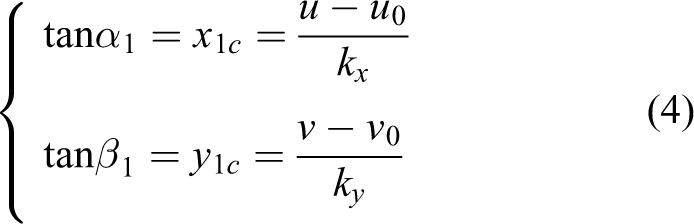
where β 1 is the angle from Z c1 to C1 P projecting on the plane Y c1 O c1 Z c1.
The depth z is computed with (2) after α 1 and α 2 are obtained. Then, the coordinates x and y are computed as given in (5). Up to now, the 3-D position (x, y, z) of point P is obtained

It can be found that the object-gazing camera C2 is very important to compute the object’s depth. It need be rotated to aim the measured object. Therefore, only one object’s depth can be measured for one time object gazing. Combining with the object’s depth, its other coordinates in the vision frame are computed from its image coordinates and the intrinsic parameters of monitor camera C1.
Calibration
Considering the error of the initial zero position of the direction of camera C2, the fixed error δ 2 of α 2 is introduced into the calibration. Thus, the calibration is to estimate the parameters Lb and δ 2.
When the fixed error δ 2 of α 2 is introduced, formula (1) is rewritten as

The value range of α 2 is (0, Π). In the case α 2≠Π/2, (6) is expanded and arranged to (7). In the case α 2 = Π/2, (6) is changed to (8)


Formulae (7) and (8) are employed to calibrate the parameters Lb and δ 2 using multiple given calibration points with known z values. α 1, α 2, and z are known variables in (7). Formula (7) is a linear equation with three unknown variables Lb , Lb tanδ 2, and tanδ 2 if Lb tanδ 2 is taken as one new variable. In (8), α 2 = Π/2, α 1 and z are known variables. Formula (8) is a linear equation with two unknown variables Lb and tanδ 2. Thus, three calibration points at least can form three equations as given in (7) or (8) at least. Lb , Lb tanδ 2, and tanδ 2 can be solved using linear least square method. Of course, more calibration points are helpful to improve the calibration accuracy.
Error analysis
From (4), we have tanα 1 = x 1c. In the following error analysis, tanα 1 is taken as one original variable and replaced by x 1c. From the difference of (2), we have

Submitting (2) into (9) to simplify, then

In addition, (11) is derived from (5)

The relative errors to z are derived from (10) and (11)


Generally, kx and ky are about 1000. dx 1c = 1/1000 if the error in image coordinates is 1 pixel. dα 2 is the resolution of stepper motor, and it is 0.9° before subdivision. It is about 0.05625° after 16 subdivision, that is, 9.82 × 10⁻⁴ rad. Considering the case, Lb = 200 mm, dLb = 4 mm, and z = 1000 mm. In this case, α 2 is about 80° or 1.3963 rad. Submitting these data into (10), we have the error dz = 30.6 mm and the relative error dz/z = 3.06%. The term zdLb /Lb = 20 mm contributes the main part in the error dz. Assume dy 1c = 1/1000, u − u 0 = 300 pixel, and v − v 0 = 200 pixel, then x 1c = 0.3 and y 1c = 0.2. Submitting then into (11), we have the errors dx = 10.2 mm and dy = 7.1 mm. Then the relative errors dx/z = 0.10% and dy/z = 0.07%. In this case, z = 2000 mm, dLb = 6 mm, and the other conditions are as the same as ones above. In this case, α 2 is about 85° or 1.4835 rad. In this case, the computed errors and relative errors are as follows. dz = 99.8 mm, dx = 31.9 mm, dy = 22.0 mm, dz/z = 4.99%, dx/z = 1.60%, and dy/z = 1.10%.
Experiments and results
Experiment system
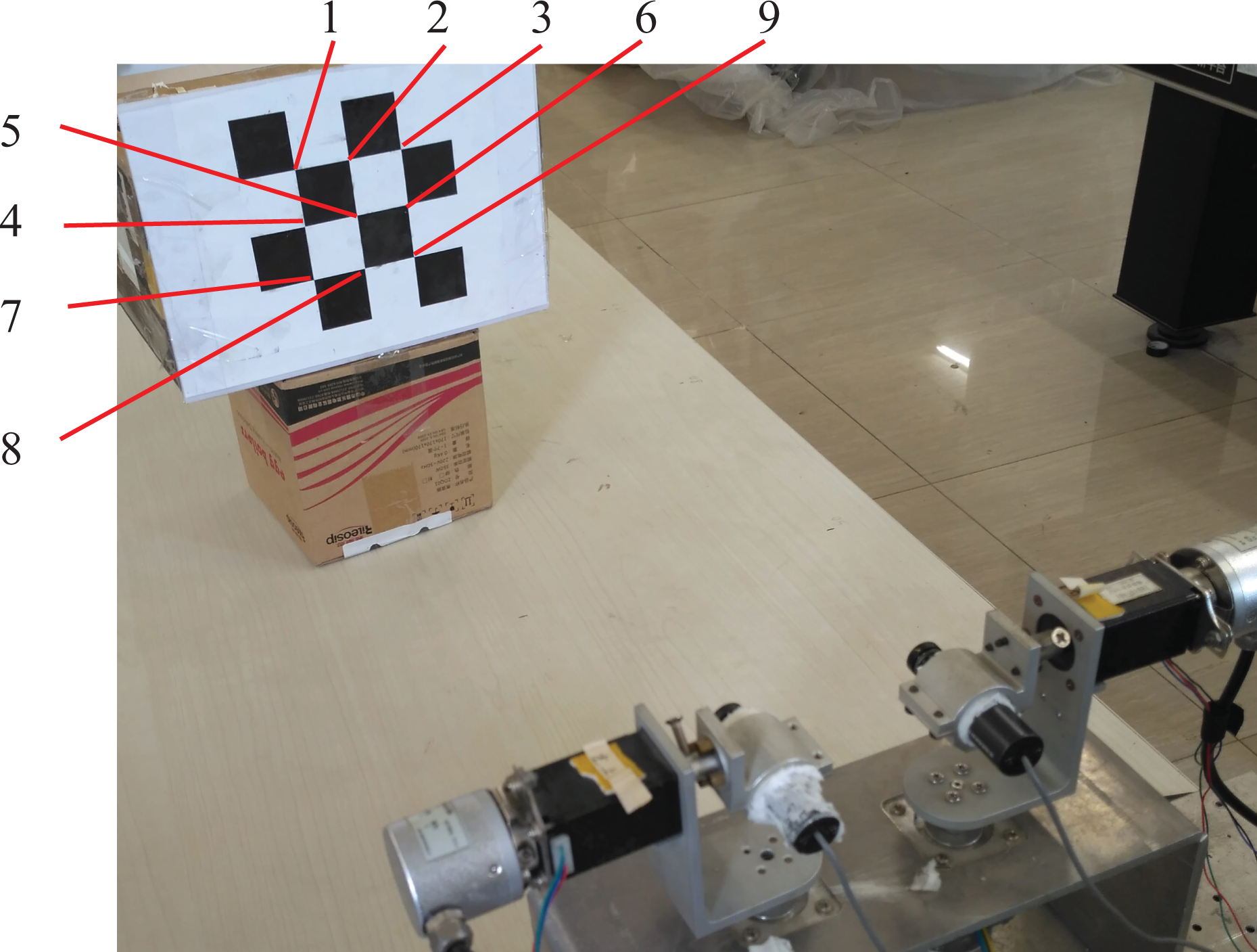
An experiment system was developed with two cameras driven by stepper motors, as shown in Figure 2. Each camera was driven by two stepper motors. One was used to yaw the camera and the other was used to pitch it. In experiments, the stepper motors D11 and D21 were fixed to keep the two cameras C1 and C2 on a horizontal plane. In the experiments with the proposed method, the camera C1 was stationary and the camera C2 was yawed by the stepper motor D22 to gaze objects. In the comparing experiments with the traditional stereovision, the two cameras C1 and C2 were fixed to the given pose. The camera’s type was OBK-2010CHEW with 1/3″ CCD. Its image size was 720 × 576 pixels, and it was resized to 400 × 300 pixels.

Experiment system.
Calibration results
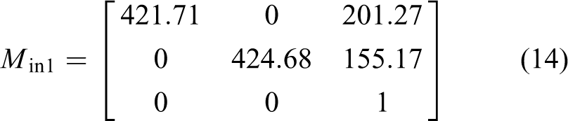
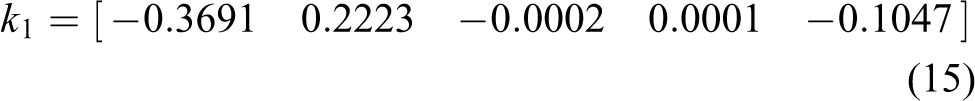
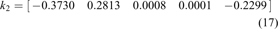
The cameras were calibrated with OpenCV for the traditional stereovision. The cameras were described with the pinhole model and Brown lens model. The results were as follows. M in1 and M in2 were the intrinsic parameter matrixes, and k 1 and k 2 were the lens distortion factors of the two cameras C1 and C2, respectively. 1 T 2 was the extrinsic parameter matrix, that is, the relative pose of the camera C2 to the camera C1


A chessboard pattern was put at different positions in front of the vision system, as shown in Figure 3. The camera C1 was stationary and the camera C2 was yawed by the stepper motor D22. Firstly, the vision system worked as the traditional stereovision after the camera C2 was yawed to the given pose. The 3-D position of the center of chessboard pattern was measured with the traditional stereovision. Then, the camera C2 was yawed to gaze the center of chessboard pattern. Its yawing angle was recorded. The collected data in the baseline calibration is listed in Table 1. The parameters Lb and tanδ 2 were computed with the method in the third section; Lb = 77.09 mm, tanδ 2 = 0.0133, and δ 2 = 0.762°.
Calibration scene.
Data in baseline calibration.

Measurement experiment
In experiments, the nine corners on the chessboard pattern as shown in Figure 3 were measured. In the measurement with the proposed method, the pattern was taken as an object. Its central corner’s depth was considered to be the pattern’s depth. It was also used for all nine corners. It was computed from the baseline and the angles when the camera C2 was yawed to gaze the central corner. In the measurement with the traditional stereovision method, all nine corners were separately computed with the intrinsic and extrinsic parameters of the cameras and the image coordinates. The measured 3-D positions of the corners were listed in Table 2. The actual depth was manually measured with a ruler.
Measured 3-D positions of the pattern corners.a
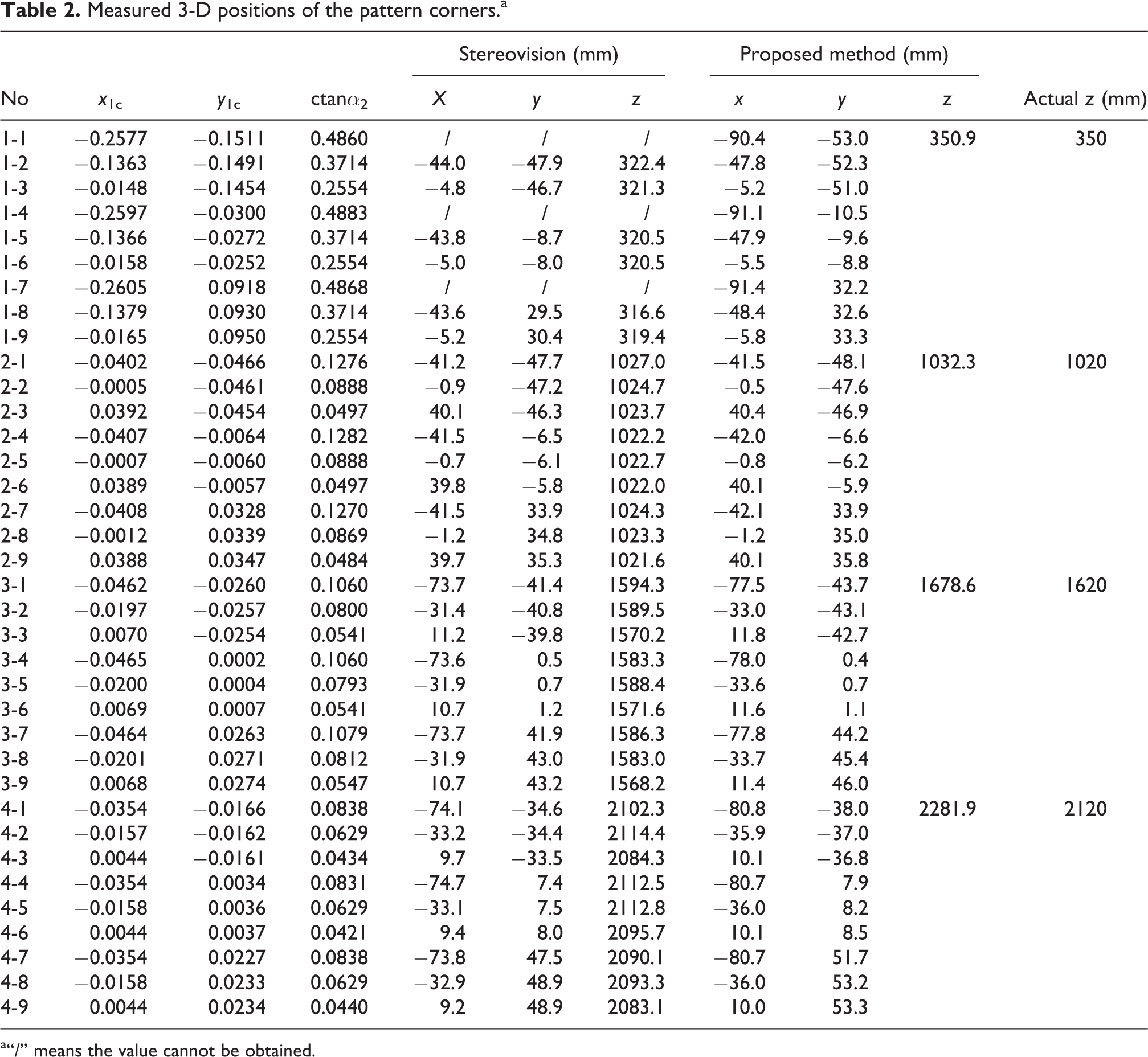
a“/” means the value cannot be obtained.
In the measurement with the traditional stereovision method, the corners numbered 1, 4, and 7 were out of the field of view of the camera C2. Their positions were absence, which are denoted with “/” as shown in Table 2. In the measurement with the proposed method, all corners were in the two cameras’ fields of view and their positions were obtained.
It can be found from Table 2 that the relative depth errors were 0.3%, 1.2%, 3.6%, and 7.5% in the four groups of experiments with the proposed method. It is coincidence with the error analysis in the fourth section. In the proposed method, all depth errors were positive. The possible reason was that the rotation axis was at the left side of the optical axis, which resulted in the positive error dLb . In the first group of experiments with the traditional stereovision method, the relative depth errors were from −9.5% to −7.9% for the corners in the field of view. They were from 0.2% to 0.7% for the second group of experiments with the traditional stereovision method. They were from −3.2% to −1.6% for the third group of experiments with the traditional stereovision method. They were from −1.7% to −0.3% for the fourth group of experiments with the traditional stereovision method. The stereovision method could not measure three points in the first group experiment since they were out of the view field of the camera C2.
On the one hand, as shown in (12) in the error analysis section, the measurement relative error will increase with the depth increment. On the other hand, it is difficult to ensure the camera’s rotation axis passes through the camera’s projection center or optical axis. It is sure that the offset of the camera’s rotation axis from its optical axis is a resource to result in the error dLb . It can be found from Table 1 that the proposed vision system was calibrated when the target was at the positions with depths from 485 mm to 1000 mm. The calibrated parameters of the proposed vision were much more suitable to this depth range. The target’s depths in the first and second group of experiments were 350 mm and 1000 mm, which were near to the target’s depths in calibration. Therefore, the measurement results in the first and second group of experiments were more accurate than others.
A pair of captured images in the measurement with the proposed method is given in Figure 4. The measured positions of the corners are shown in Figure 5. It can be found from Figure 5 and Table 2 that the measurement accuracy with the proposed method was as same level as one with the stereovision method. But the proposed method can work in a larger range.

Captured images: (a) camera C1 and (b) camera C2.

Measured positions of the corners: (a) XOZ, (b) YOZ, and (c) 3-D.
Measurement experiment for large size component
In industrial manufacturing, the components to be fabricated sometimes are of large size. For example, the metal plate in sheet metal fabrication may have large size up to 2 m long and 1 m wide. The traditional stereovision cannot have such large a common field of view to measure the metal plate’s size when it is near to the vision system.
As the imitation of the components in sheet metal fabrication, three plate components in office were used to test the measurement with the developed vision system. Figure 6 shows the images in the process to measure the first long plate. Figure 6(a) is the image captured by the camera C1. Figure 6(b), 6(c), and 6(d) are the images captured by the camera C2 at the initial pose, the pose to measure far point, and the pose to measure near point, respectively. It can be found from Figure 6 that the camera C2 cannot capture the whole image of the long plate at above poses. In other words, it is difficult to measure the size of the long plate with the traditional stereovision system.

Captured images of first long plate component: (a) camera C1, (b) camera C2 at initial pose, (c) camera C2 at the pose to measure far point, and (d) camera C2 at the pose to measure near point.
In the measurement procedure, the camera C2 was firstly yawed to gaze the far point of the long plate, and the coordinates of the far point were computed with the proposed method. Secondly, the camera C2 was yawed to gaze the near point of the long plate, and the coordinates of the near point were computed. Then the length of the long plate was calculated from the far and near points. In the experiments, three components were measured. The other two components were shown in Figure 7. Their measured lengths were 1207.2 mm, 529.6 mm, and 399.3 mm, respectively. Their actual lengths were 1400 mm, 500 mm, and 400 mm, respectively. The actual lengths were manually measured with a ruler. The measurement error was large for the first long plate component since its smooth corners reduced the match accuracy of the corresponding feature points. The measurement errors were much small for the second and third plate components since their sharp corners were helpful to ensure the match accuracy of the corresponding feature points.

Captured images of other two plate components: (a) image of second component captured by camera C1 and (b) image of third component captured by camera C1.
Conclusion
The main contribution of this work is the developed new active vision system. It monitors objects with a fixed camera and gazes them with an active yawing camera. The object’s depth is computed from the baseline, image coordinates in the fixed camera, and the yawing angle of the object-gazing camera. Then the object’s other coordinates in Cartesian space are calculated with the depth and the normalized imaging coordinates. Experimental results verify the effectiveness of the proposed active vision system and measurement method.
The proposed vision system has much larger measurement range, more flexibility, and better convenience of application and maintenance than the traditional stereovision system.
In future, we will focus on the improvement of measurement accuracy with the proposed vision system. More factors such as the resolution of the cameras, the lens distortion, the position of rotation axis of camera C2, and the chessboard pattern 20 will be taken into account.
Footnotes
Declaration of conflicting interests
The author(s) declared no potential conflicts of interest with respect to the research, authorship, and/or publication of this article.
Funding
The author(s) disclosed receipt of the following financial support for the research, authorship, and/or publication of this article: This work was supported in part by the National Natural Science Foundation of China under grants 61421004, 61227804, and 61403378 and the National High Technology Research and Development Program of China (863) under grant 2015AA042307.