
Abstract
This paper presents the use of a hybrid collaborative stereo vision system (3D-distributed visual sensing using different kinds of vision cameras) for the autonomous navigation of a wheeled robot team. It is proposed a triangulation-based method for the 3D-posture computation of an unknown object by considering the collaborative hybrid stereo vision system, and this way to steer the robot team to a desired position relative to such object while maintaining a desired robot formation. Experimental results with real mobile robots are included to validate the proposed vision system.
Introduction
Artificial vision systems have been widely used as external sensors in mobile robotics applications due to the large amount of information that they can offer. For this reason, they have nowadays become the most used sensors in tasks such as surveillance, search, exploration, rescue, mapping, obstacle detection and they have been used for autonomous navigation (Carelli et al., 2006b; Couto et al., 2008; Koyasu et al., 2001; Koyasu et al., 2002; Nebot & Cervera, 2008; Okamoto & Grassi, 2002; Soria et al., 2007; Toibero et al., 2009; Vassallo et al., 2005). Moreover, the use of two or more cameras simultaneously gives the system the 3D perception, allowing it to successfully perform different tasks in completely unknown environments. Additional advantages could be obtained by including onmidirectional cameras into the system (Correa & Okamoto, 2005; Gluckman et al., 1998, Koyasu et al., 2001; Koyasu et al., 2002). These cameras allow increasing the horizontal visual field up to 360°, but loosing image resolution. Another choice is to combine omnidirectional cameras with perspective-transformation cameras constructing a new hybrid stereo vision system, which have the advantages of both above mentioned kind of vision cameras (Adorni et al., 2001; Sturm, 2002). It is a well known fact that many tasks could be performed more efficiently by considering two or more robots working cooperatively (De la Cruz & Carelli, 2008; Carelli et al., 2006a; Das et al., 2002; Fierro et al., 2002; Renaud et al., 2004; Roberti et al., 2007; Tanner & Kumar 2005; Toibero et al., 2008). A similar situation could be thought for the stereo vision system, where each camera is mounted on a different robot introducing a new collaboration degree between the robots in the team. Hence, the robots not only execute a cooperative task but also help to perform a collaborative environmental sensing which is necessary to carry out the task. This concept of vision sensors distribution among the different robots in the team not only reduces the computational effort by dividing image processing tasks, but also allows introducing a reconfigurable stereo vision system able to be adapted to the varying conditions imposed by the robot surroundings (Zhu et al., 2004; Cervera, 2005).
In this paper it is considered the use of a collaborative hybrid stereo vision system (3D distributed visual sensing using different types of vision cameras) for the autonomous navigation of a mobile robot team. It is proposed a triangulation-based method for the posture computation of an unknown object in the tridimensional space by using the hybrid collaborative stereo vision system, and the steering the robot team to a desired goal position relative to such object (Soria et al., 2007) while maintaining a desired robot formation by a centralized formation control algorithm (Roberti et al., 2007).
Some previous papers consider collaborative visual sensing in robotics. In (Hajjawi & Shirkhodaie, 2002) one robot pick up an object using the information obtained by the camera of another robot of the multi-robot system. In (Spletzer et al., 2001) the catadioptric vision system of each robot is used to obtain the relative position between the robots in a decentralized scheme. Closer to our work, (Zhu et al., 2004) and (Cervera, 2005) consider reconfigurable stereo vision systems. In the work of (Zhu et al., 2004) it is introduced a reconfigurable vision system composed by two onmidirectional cameras and it is proposed its use to perform a human being following task within a surveillance scope. In the work of (Cervera, 2005) the vision system is integrated exclusively by perspective transformation cameras and exposes its use in object-manipulation tasks by considering a mobile manipulator. Different from these papers, our work proposes the construction of a hybrid collaborative vision system and its use for the autonomous navigation of a robot team.
The remainder of this paper is organized as follows. Section 2 summarizes the different vision systems models employed along the paper and presents the proposed hybrid stereo vision system. Section 3 explains the collaborative sensing implementation. Sections 4 and 5 deal with the control strategies considered for the autonomous robot team navigation. Section 6 exposes the experimental results obtained and finally, Section 7 states conclusions and describe future related works.
Vision system models
A vision camera transforms a 3D space into a 2D projection on the image plane, where the vision sensor is located. This projection causes the lost of the depth perception, which means that each point on the image plane corresponds to a ray in the 3D space.
PerspectivePprojection Camera Model
Several projection models for the representation of the image formation process have been proposed. The most used is the perspective projection model or “pin-hole” model. In this model, a coordinate system 〈0P, PX, PY, PZ〉 attached to the camera is defined in such a way that the X and Y axes define a base for the image plane and the Z axis is parallel to the optic axis. The origin of the framework 〈0P, PX, PY, PZ〉 is located at the focus of the camera lens. From Fig.1.a, a fixed point
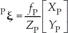
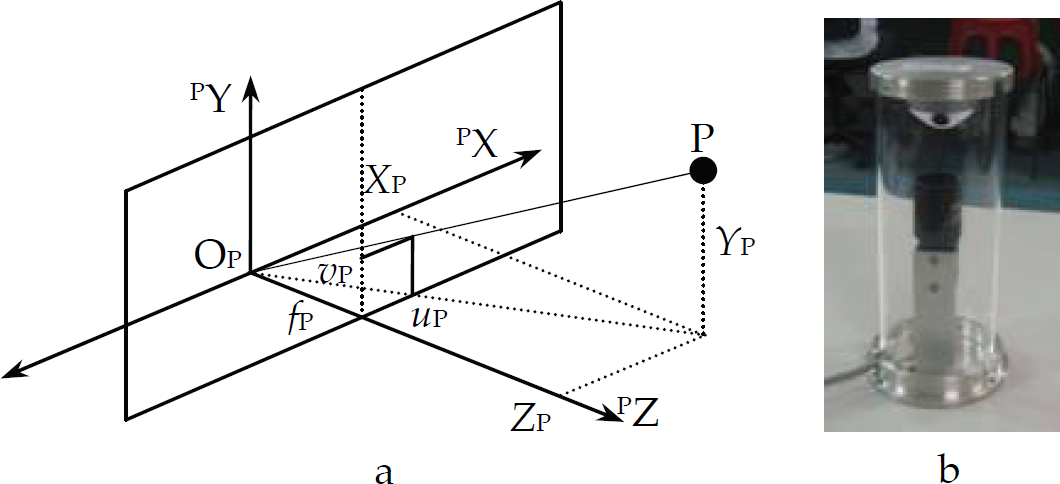
a) Perspective projection camera model; 1. b) Catadioptric vision system
where fP is the focal length of the camera expressed in pixels.
Omnidirectional vision systems allow obtaining 360
In the framework 〈0ᴏ, ᴏX, ᴏY, OZ〉 attached to the perspective camera of the catadioptric system, the equation that describes the hyperbolic mirror geometric is,

Both vision systems briefly described in the above sections could be combined with the aim of constructing a stereo vision system in order to obtain depth perception (Adorni et al., 2001). With this stereo vision system, it will be possible to get the 3D coordinates of an object without any previous knowledge about it. The structure of the proposed vision system is shown in Fig. 2.
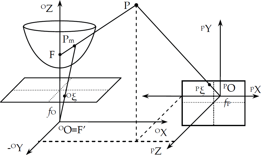
Stereo vision system
In Fig. 2 the coordinates of the relevant points are,
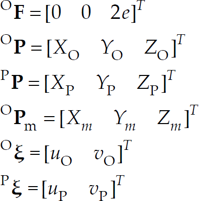
where ᴏ
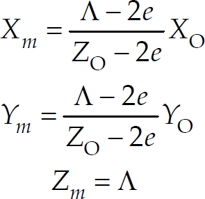
The objective of this Section is to find the equation system that allows getting the 3D coordinates of the point of interest
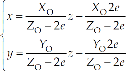
and introducing (4) in (2), a second order equation in z, that represent the z-coordinates of the two points where the ray
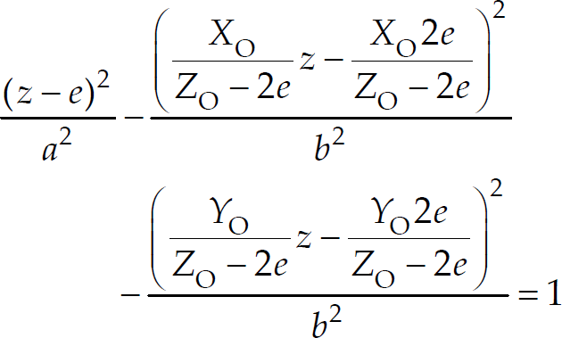
Operating and reorganizing (5),
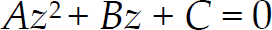
With
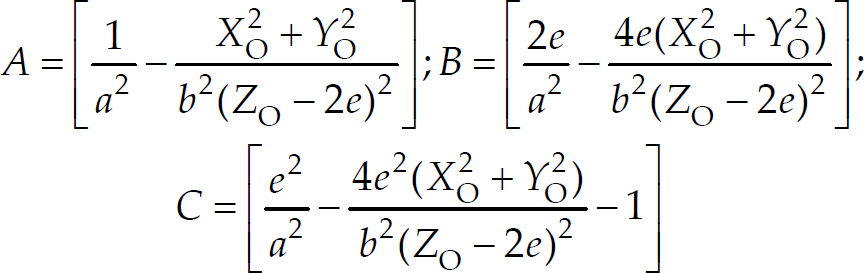
Then, (6) can be solved by using

The value Λ will be the z-coordinate of the point ᴏ
Now, the pin-hole model of the perspective camera in the omnidirectional system,

can be used to get the projection of the point ᴏ

By taking into account that PP and OP are the same point of interest represented in two different coordinate systems, it is possible to relate them by

where

where r
ij
and t
i
are the elements of the matrix
Now, XP, YP, XO and YO in (12) can be replaced using (1) and (10), thus obtaining the following three-equation system of three variables (γ, ZO, ZP),

where
The three-equation system (13) allows getting the z-coordinate of the point of interest
Remark
Note that (13) has been found considering hyperbolic shape mirror and its application is restricted to this kind of catadioptric vision systems. Nevertheless, it can be generalized for any mirror shape if it is considered the general projection model (Geyer & Daniilidis, 2000). In this case, (13) becomes,

where l and m are parameters of the general projection model;
The proposed hybrid stereo vision system was first tested in static experiments under laboratory conditions. The omnidirectional vision system includes a perspective projection camera “Flea” manufactured by Point Grey (resolution: 1024times768 pixels) and a hyperbolic mirror as explained in previous section; and the conventional vision system is a perspective projection camera Sony EVI-D31 (resolution: 640times480 pixels; and f
p
= 765 pixels). The relative position adopted between both individual vision systems is defined by,

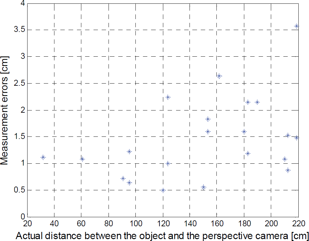
With the constructed stereo system, a set of images was acquired. For each pair of images, the interest object was located at different places. After determining the projection of the interest object in both image planes (ᴏξ and Pξ), the proposed equation system (13) is solved in order to determine the 3D position of the object in the framework attached to the perspective projection camera. The results are shown in Figures 3, 4, 5, 6 and 7.

3D points reconstruction.
Error between the actual and measured positions.

Position error between the actual and measured positions of the object in x-coordinate.
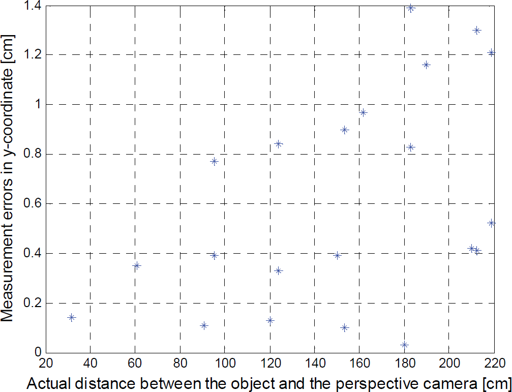
Position error between the actual and measured positions of the object in y-coordinate.
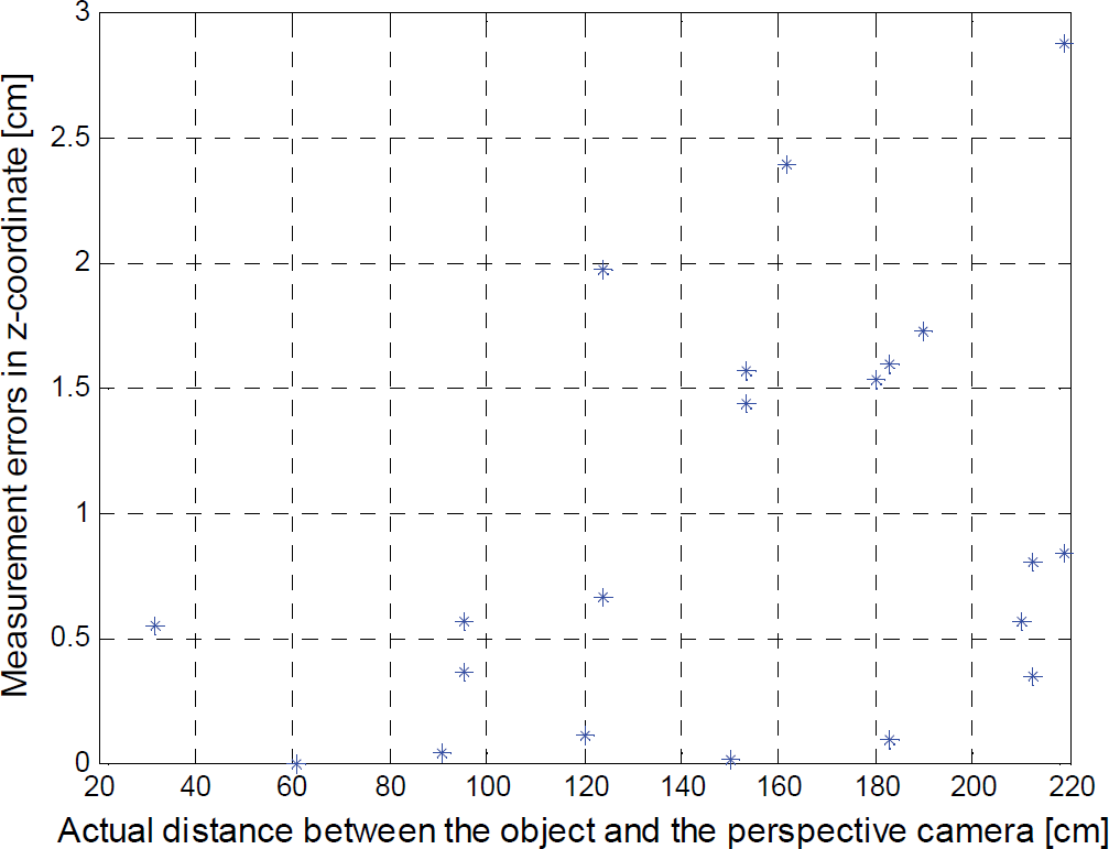
Position error between the actual and measured positions of the object in z-coordinate.
Figure 3 shows the results in the reconstruction of the object position. The position error between the actual position and the position obtained by solving (13) can be seen in Figure 4. This error is calculated as the 3D Euclidean distance between both positions. Figures 5, 6 and 7 show the position error between the actual position of the object and the position obtained by solving (13) in x, y and z coordinates respectively. These Figures show that measurement errors are in most cases fewer than 3 centimiters.
The hybrid stereo vision system proposed in the above Section is used as a collaborative sensor in a leader based multi-robot system. The leader robot is equipped with a catadioptric vision system and the follower robot has the perspective projection camera. Both the leader and the follower robot collaborate to obtain information of the environment with the aim of guiding the multi-robot system to a desired final position relative to an unknown object, defined by the distance ρ and the angles ψ and φ as can be seen in Fig.8. These ρ-distance and the two angles ψ and φ are obtained from the (not vertically aligned) unknown object corner positions


Robot-object relative posture
where (xP1; yP1) and (xP2; yP2) are de coordinates of the points
Therefore, the proposed control system is shown in Fig.9. It includes a formation controller to ensure that the follower robot reaches and keep the desired formation while following the leader; and the leader controller to make it capable to guide the robot team to the desired position relative to the unknown object. Both, the formation controller and the leader controller run in the leader robot's on-board computer. The catadioptric vision system of the leader robot is also used to obtain the follower robot's posture needed in the formation control algorithm.

Proposed control system
The coordinated navigation for the robot team is achieved by considering the formation control proposed by the authors in (Roberti et al., 2007), which allows the robots to reach a specific formation, and to maintain it while the robots navigate in the workspace. This formation controller is based on a centralized leader-following technique, i.e., the leader robot navigates under its own control law sensing the followers' posture (relative to its own reference framework). With this information the leader computes the control actions to be send to each follower in order to successfully accomplish the navigation objective under formation. Follower robots are considered as unicycle-like robots navigating with linear velocity v and orientation α on the coordinate system 〈O, LX, LY〉 attached to the leader robot. By considering the robot as the punctual object C, the following equation set can describe this movement

where v'y Ω are the leader robot linear and angular velocities (and hence, the velocities that rule its associated framework movement); ω is the follower robot angular velocity; d-distance and θ-angle define the follower robot position with respect to the leader robot according to Fig.10.

Robot kinematic model
In order to compute an error between the actual positions of each robot and its desired positions in the formation, let


Actual and desired positions
The formation error is defined as follows,

where
has full rank. Vector

The control objective is to guarantee that the multi-robot system asymptotically reaches the desired formation defined by

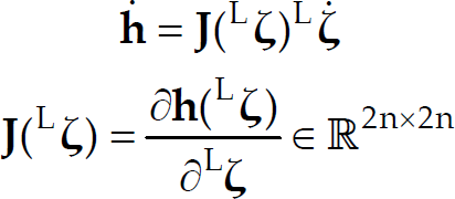
First, from (22) a vector of reference velocities for the robots is defined as,

where
Now, assuming perfect velocity tracking, that is
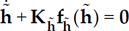
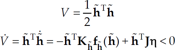
By introducing the following Lyapunov candidate and its time derivative (Slotine & Li, 1991),

it is clear that
The control actions for the linear and angular velocities of each robot will be calculated to ensure the robots reach the velocity reference
where
By equating (26) with the third equation of (18), the close loop equation becomes,

By introducing the following Lyapunov candidate and its time derivative [13],

it can be concluded that
The proposed control law for the linear velocity is,

which obviously produces that
In the above controller design it has been proven that

Equation (30) considers a more realistic situation in which the follower robots reach asymptotically the velocity reference instead of assuming perfect velocity tracking, as made before. Considering the following Lyapunov candidate and its time derivative (Slotine & Li, 1991),
a sufficient condition for the second equation of (31) to be negative definite is,

where
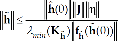
But, as
The leader robot navigates accordingly to the control laws proposed by (Soria et al., 2007). This controller generates the linear and angular velocity commands (v' C and Ω C ) in order to set its position (and consequently, the whole team) in front of an unknown object. Such commands are obtained as functions of the robot-object relative posture, defined by the distance ρ and the angles ψ and φ, as explained in Section 3.
The control objective is to maintain the robot at certain fixed distance ρ
d
behind the object with φ = φ
d
considering only the robot-object information provided by the collaborative stereo vision system. This way, some characteristic problems due to odometry errors can be avoided. Nevertheless, the vision system must be fast and precise, guaranteeing the controller quality. Being

The robot-object relative position evolution will be given by their time derivatives. Where the distance error variation is given by the difference between the velocity projections of the robot (v') and the object (vT) on the line
Analogously, the φ-angle variation has three terms: the leader robot angular velocity Ω and the rotational effect produced by the linear velocities of both: the robot and the objective. This could be written as,

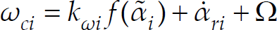
Next, it is proposed the following controller which satisfies the control objective (34),

where
For more details about these control laws and their stability proof, refer to (Soria et al., 2007).
In order to validate the proposed method for reconstructing the 3D position of an unknown object, a collaborative sensing experiment using the hybrid stereo vision system was carried out. The experimental setup is a mobile robot team consisting of two mobile robots Pioneer (manufactured by Mobile Robots Inc.). The leader robot has the catadioptric vision system and the follower robot has the conventional perspective projection camera. Figure 12 shows the experimental setup. In the experiment, the team of robots must navigate autonomously maintaining a desired formation (ζ d = [500 0]T expressed in millimetres) until they reach a desired posture (ρ d = 1000 mm and φ d = 15°) relative to a static unknown object (v T = 0).

Experimental setup
By using the hybrid collaborative stereo vision system, the team gets the posture of the unknown object relative to the leader robot, necessary in (37); and with the catadioptric vision system, the leader robot obtains the posture of the follower robot relative to its own framework, required in (23), (26) and (29). Additionally, the posture of the follower robot allows the leader to determine the matrix

Robot-object position error

Robot-object angular error

Linear and angular commands for the leader robot

Formation error

Linear and angular commands for the follower robot
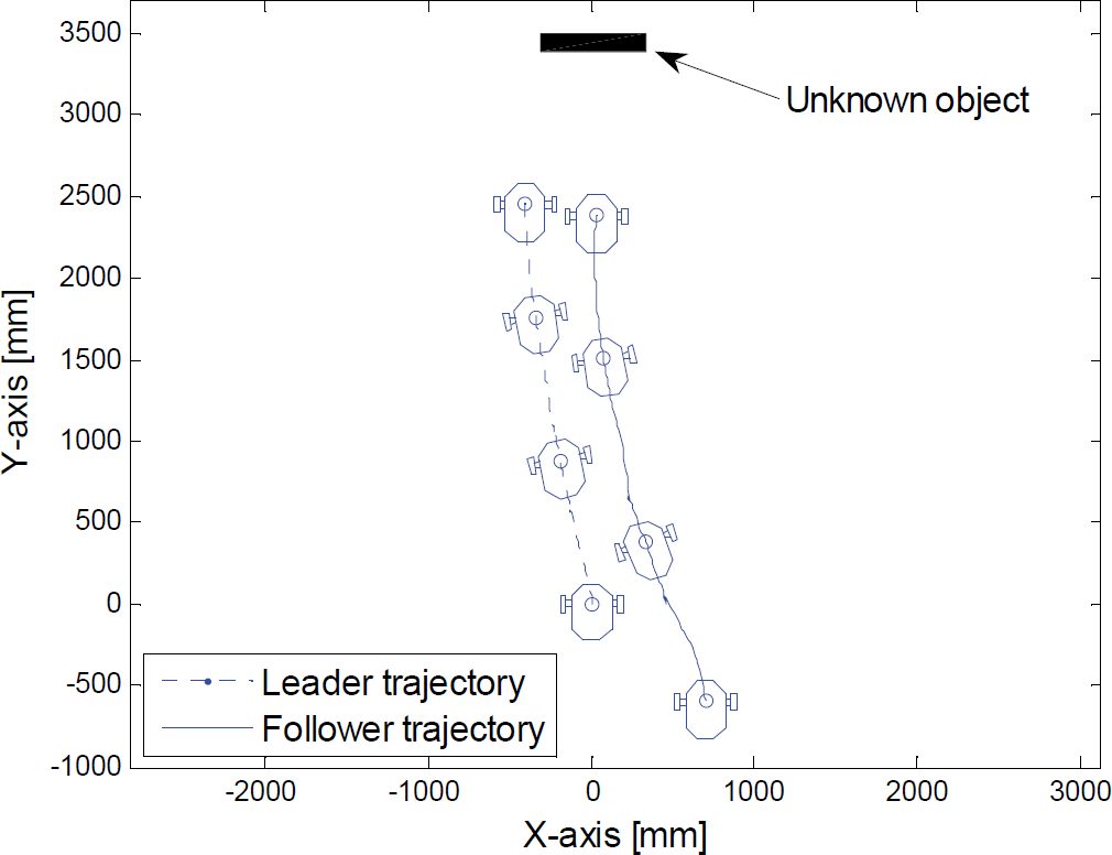
Trajectories described by the robots
Figure 13 shows the evolution of the distance error
The results obtained show the good performance of the collaborative hybrid stereo vision system proposed for mobile robotics applications.
In this paper, it has been presented a collaborative hybrid stereo vision system, i.e., a stereo vision system composed by a perspective transformation camera and a catadioptric camera, each one mounted on different mobile robots. This way, both robots collaborate on the environment information extraction needed to satisfy the proposed control objectives. Also, the stereo vision system can be re-configured with the aim of obtaining the best quantity and the better environment information quality. Furthermore, experimental results that clearly show the good performance of this vision system when applied to the mobile robot navigation have been presented.
Future works on this subject, will address the implementation of collaborative vision systems with more than two cameras, the proposal for new algorithms to compute the best vision system configuration and consequently the desired position of each robot into the desired formation. Furthermore, the consideration of Scale Invariant Features Transform (SIFT) algorithms for the image features extraction and for the determination of correspondence between the points on different images would add robustness to the vision system.
Footnotes
8. Acknowlegment
Authors thanks to the National Council of Scientific Research of Argentina (CONICET) por partially support this research.