
Abstract
Hybrid underwater glider combines motion modes of traditional autonomous underwater glider and those of autonomous underwater vehicles. Different motion modes need different flight performance, including flight efficiency, static stability, and maneuverability. Conventional hybrid underwater glider with fixed wings can’t achieve optimal flight performance in one flight mission demanding various motion modes. In this article, controllable wings for hybrid underwater glider Petrel II are designed. Angle of attack, sweep angle, and aspect ratio of controllable wings can be changed to adapt to different motion modes. Kinematics and dynamics models of Petrel II are established based on multibody theory. Motion simulations of Petrel II with different wing configurations are conducted in three motion modes, including glide motion, spiral motion, and horizontal turning motion. The simulation results show the impact of wing parameters on flight performance. Field trials demonstrate that the controllable wings can improve the flight performance.
Introduction
Autonomous underwater glider (AUG) is an economic and promising marine observation platform in terms of small size, long duration, and a harvest of oceanographic data. Volume-varying bladder provides buoyancy. Movable and rotary battery pack distributes mass to change pitch and roll angles. Wings convert vertical force into forward force. Therefore, AUG achieves saw-tooth trajectory. 1 At present, widely recognized AUGs include Slocum, 2 Seaglider, 3 and Spray. 4 Compared with AUG, hybrid underwater glider (HUG) with an auxiliary propeller gets the high speed and maneuverability at cost of duration but performs excellently in horizontal cruise, obstacle avoidance, and fast track. HUG Petrel II developed by Tianjin University has been put into use since 2014. It is 2.3 m in length without regard to antenna, 0.22 m in diameter, and 69 kg in weight. During the latest sea trial, Petrel II sailed 1108.4 km, dived 1514.2 m deep, and had the maximum glide speed of 0.82 m/s and propeller speed of 1.73 m/s, indicating good flight performance.
Flat, thin, and fixed wings are adopted by Petrel II in view of the glider’s low-speed and saw-tooth motion. However, fixed wings can’t achieve optimal flight performance to meet the long endurance demand of large-scale environmental monitoring or maneuverability demand of sub-mesoscale eddy tracking, adaptive sampling, or obstacle avoidance at the same time. 5 –7 Thus, controllable wings become a solution to satisfy HUG’s various flight performance demands. Some advanced materials, such as shape memory alloy and ionic conducting polymer film, are used to achieve the transformation of the wings. 8 –10 However, mechanical structures are still the most popular among researchers. M. Arima developed a glider prototype named ALEX. 11 With independently controllable wings, which can change angle of attack (AOA), ALEX has high maneuverability. Isa K established a dynamic model of HUG named USM with controllable wings and designed a neural network predictive control method. Gliding and hovering motions are analyzed. 12,13 Xie focused on glide efficiency of underwater gliders with passively rotatable wings. Simulation shows that the lift-drag ratio and AOA present a quadratic function relation. 14 Researches shown earlier focus on AOA only. In this article, parameters of controllable wings are extended. AOA, sweep angle, and aspect ratio all can be adjusted as shown in Figure 1.

Three wing configurations.
This article is organized as follows. “System design” section introduces the basic structure of Petrel II and controllable wings system. “Multibody kinematics” section establishes the kinematic model of Petrel II with controllable wings. “Multibody dynamics” section analyzes the forces and moments acting on Petrel II and establishes the dynamic model. “Motion simulation” section simulates five motions with different wing configurations. “Field trial” section shows results of field trials. Finally, conclusions and future work are discussed in “Conclusions and future work” section.
System design
Petrel II with controllable wings consists of six subsystems: buoyancy engine system, attitude adjustment system, controllable wings system, control system, propeller engine system, and communication and location system as shown in Figure 2. An independent cabin is added to contain the controllable wings system. The wing on the right side is described in detail.
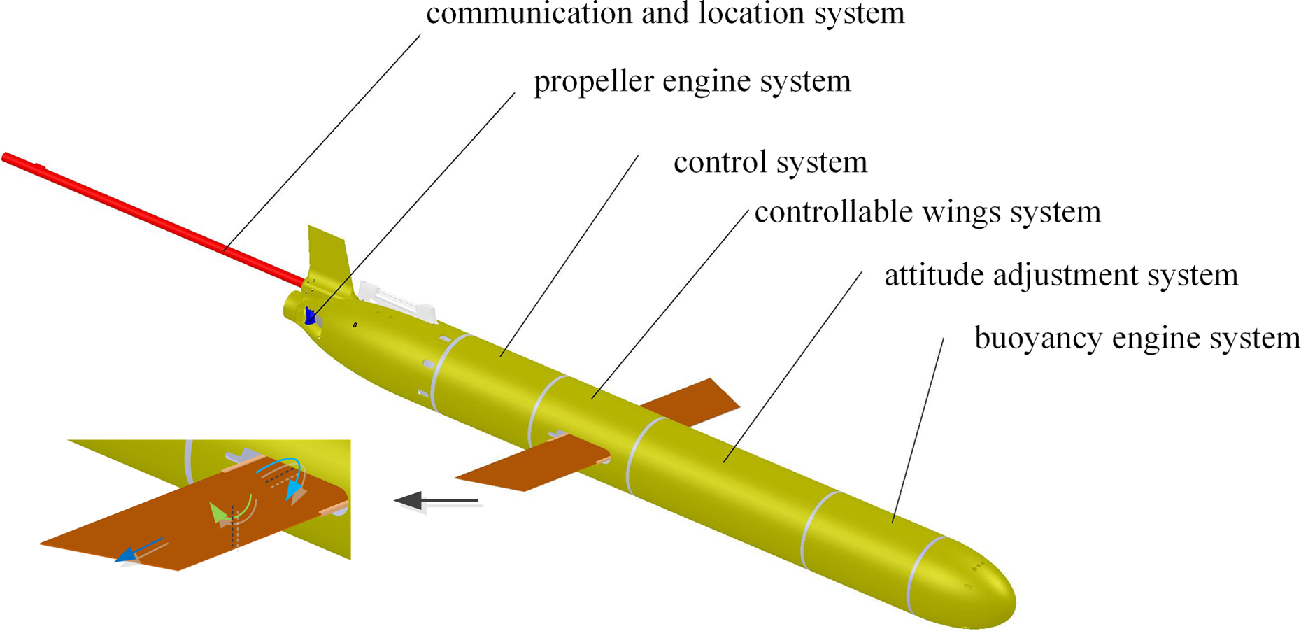
System layout of Petrel II with controllable wings.
The controllable wings system consists of two parts: wings and drive mechanism. Each wing is made up of three separate parts: wing A, wing B, and wing C, as shown in Figure 3. Wing A and glider body form a revolute pair. Wing B and wing A form a revolute pair. Wing C and wing B form a sliding pair. Motions of wing A and wing B will be transmitted to wing C. Thus, wing C has three degrees of freedom (DoFs) relative to the glider body. 15
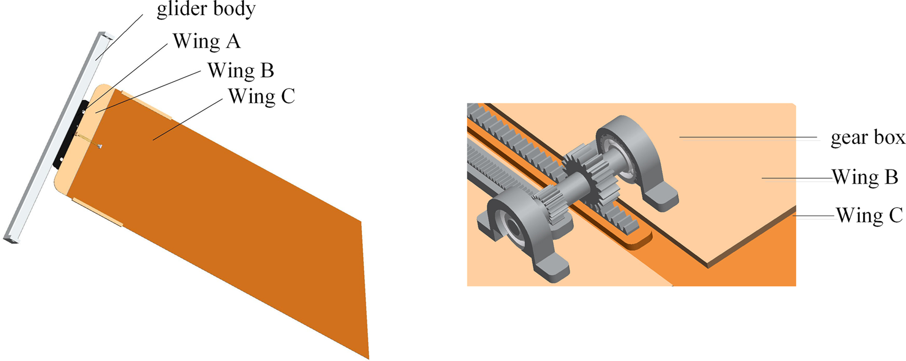
Structure of controllable wings.
The drive mechanism includes mechanism I and mechanism II as shown in Figure 4. Wing A is fixed to the double rocker mechanism. Wing B is fixed to the crank slider mechanism. Wing C matches with the output slider C. Mechanism I is a combination of double parallelogram linkages ABCDHG and plane five-bar linkages DFEGH using linkage synthesis. 16 Single plane five-bar linkages can achieve two linear movements. However, when any output bar moves along one axis, revolution always exists. 17 Double parallelogram linkages’ output bar CD possesses two linear movements which are yet not certain. Mechanism I realizes certain linear motion of output bar CD by combining two linkages as shown in Figure 5.

Drive mechanism.
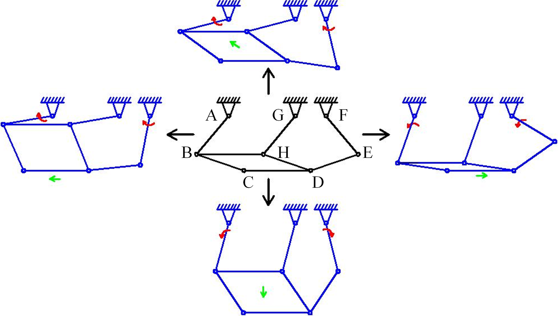
Motion course of mechanism I.
Mechanism II includes displacement multiplication mechanism, crank slider mechanism, and double rocker mechanism. At the initial stage, the output bar CD is separated from mechanism II. When CD moves in specific ways, specific output slider pairs will match. When output slider A and A′ match, the crank slider mechanism fixed with wing B will rotate to change sweep angle. When output slider B and B′ match, the double rocker mechanism fixed with wing A will rotate to change AOA. When output slider C moves linearly forward along wing B, the displacement multiplication mechanism using duplicate gear will make wing C move 3 times the distance of slider C to change wingspan. The variation ranges of AOA, sweep angle, and aspect ratio are 0–55°, 0–70°, and 6–8, respectively. 15
Multibody kinematics
A multibody system is a system consisting of a set of bodies connected to one another through internal joints and to the rest of the world through external joints or contacts. 18 Traditional methods take HUG as a single particle and miss some HUG’s dynamic characteristics. With the help of multibody theory, every single part of HUG can be analyzed. In this article, the multibody dynamic method proposed by Huston is adopted. 19,20
Lower body array
Petrel II with controllable wings can be divided into six components, including the glider body, battery pack, hydraulic oil, propeller, the left wing, and the right wing. The six components are orderly represented by BK (K = 1 − 6)
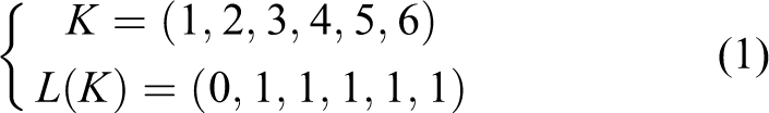
where K is body number and L(K) is lower body array (LBA).
Coordinate establishment
To satisfy multibody analysis, seven coordinates are established. One is the inertial coordinate and the others are body-fixed coordinates. As shown in Figure 6, the inertial coordinate E-XYZ is assigned by standard definition. The origin of E is on the surface of sea, axis EY vertically points upward and axis EX horizontally points north. The body-fixed coordinate of B
1, also called moving coordinate B-xyz, is established in such a way that the origin is the buoyancy center of neutrally buoyant glider, axis Bx is parallel to the long axis of the glider body, and axis Bz lies along the right side of the glider body. Other body-fixed coordinates are

Coordinates of multibody system.
Petrel II has 16 DoFs. The glider body has six DoFs (φ, ψ, θ, x, y, z). The battery pack has two DoFs, including translation of Lb and rotation of θb . The propeller has one DoF θp . Hydraulic oil, out and in, has one DoF Lo . Each of the two wings has three DoFs. The right wing has translation Lrw and rotations θrwy and θrwz .
Transformation matrix

In multibody dynamic analysis, Euler parameters (ε1, ε2, ε3, ε4, ε5) are used to represent objective’s attitude to avoid singular points

where Sij represents the element of transformation matrix

Then Euler parameters of B1 can be determined

Euler parameters of body B 2, B 3, and B 6 with rotational DoFs are shown

Generalized speed
The whole system has 16 DoFs and 16 generalized coordinates. Sixteen generalized speeds ql (l = 1∼16) are used to represent 16 DoFs
where V means velocity and angular velocity component in the body coordinate system. It is zero if there is no rotational or translational component. [pi, qi, r i ] is angular velocity of glider components. [ui, vi, w i ] is linear velocity of glider components.
Centroid velocity, centroid acceleration, angular velocity, and angular acceleration
Centroid velocity, centroid acceleration, angular velocity, and angular acceleration of multibody system can be described as below 19,20

where noe is the orthonormal unit vector in the inertial coordinate. ωklm is the partial angular vector scalar component about noe, and υklm is the partial velocity vector scalar component about noe. The subscript k (1∼6), l (1∼16), and m (1∼3) represent six body components, 16 generalized speed, and three coordinate components, respectively.
Multibody dynamics
Forces and moments analysis
Petrel II with controllable wings is subjected to the following forces: gravity, buoyancy, propeller thrust, and hydrodynamic forces.
Gravity and buoyancy
The rotation and movement of the battery pack change the gravity center and produce moment. The oil distribution changes the buoyancy and makes the buoyancy center move along axis Bx, thus producing moment. The gravity and buoyancy forces are expressed as 21
where G is the magnitude of gravity and B is the magnitude of buoyancy. (xG, yG, zG) and (xB, 0, 0) are the coordinates of gravity center and buoyancy center of the glider body in B-xyz, respectively.
Propeller thrust
The propeller generates thrust and moment along an axis which deflects 2° about axis Bx in plane Bxz to overcome the deflection moment. The force and moment can be expressed as 22

where KT is the thrust coefficient, KQ is the moment coefficient, ρ is the density of sea water, n is the rotating speed of the propeller, and D is the diameter of the propeller.
Hydrodynamic forces
The hydrodynamic forces include inertial hydrodynamic forces and viscous hydrodynamic forces. Inertial hydrodynamic force is generated when the glider operates in an unsteady state and is linearly proportional to the acceleration and angular acceleration of the glider. The inertial hydrodynamic force of HUG is the sum of forces acting on the glider body and controllable wings.
The glider body has 6 DoFs and 36 inertial forces, but with two symmetrical planes, the 26 acceleration coefficients are zero. The inertial hydrodynamic forces acting on the glider body and controllable wings can be described as 23

where λ is acceleration coefficient, λ62 = λ26 and λ53 = λ35.
As forces acting on the wings are along Bz, λw33 = λw35 = λw53 = 0. The acceleration coefficients of a single wing are approximate to those of a flat plate with finite length and width as below 24

where c is the chord, b is half wingspan, δ is the flip angle of wing, and xw is the distance between action spot of hydrodynamic force and the gravity center along axis Bx.
Viscous hydrodynamic force is the viscous drag when the glider is shearing the fluid. The viscous hydrodynamic force acting on the body can be described as 25

where S is the maximum cross-sectional area of the glider body and V is the magnitude of the vehicle velocity in the body-fixed coordinate. α is the AoA and β is slide angle. C and T are the linear hydrodynamic coefficient calculated by FLUENT.
As to controllable wings, whose shape and attitude always change, viscous hydrodynamic force coefficients of the wings can be approximately estimated 26

where Cxw is coefficient of longitudinal force, Cyw is coefficient of vertical force, Czw is coefficient of lateral force, Mxw is coefficient of roll moment, Myw is coefficient of yaw moment, Mzw is coefficient of pitch moment, λ is aspect ratio, η is sweep angle, CDO is 2-dimension profile coefficient of minimum drag, CDC is coefficient of lateral drag, and αw is whole attack angle of wings, which can be expressed as

where α is the AOA of the glider and δ is the flip angle of the wings.
Coordinate transformation of forces and moments
The forces above are conducted in the body-fixed coordinate. When converted to the inertial coordinate system numbered zero, force Fk and moment Mk are

The generalized force corresponding to the generalized active speed is 19

where Fklm and Mklm are scalar components of Fk and Mk along noe, respectively.
Kane equation
Based on multibody system dynamics, the Kane equation is used to describe the system 27

where Fl and

where αlp is generalized inertial coefficient and hl is generalized inertial force coefficient.
Motion simulation
HUG integrates the motion modes of AUG and autonomous underwater vehicle (AUV). When working in AUG mode, Petrel II has the advantage of long endurance and operates in glide motion and spiral motion. When working in AUV mode, Petrel II gets the high speed and horizontal turning capacity. Glide motion emphasizes flight efficiency and static stability. Spiral motion and horizontal turning emphasize maneuverability. All motions need static stability. Former study shows that sweep angle affects the static stability of Petrel II most. However, the static stability is always below zero. 28 For Petrel II with controllable wings, the static stability changes slightly when the sweep angle changes as shown in Table 1.
Static stability changes with the sweep angle.

There are many researches about effect of AOA on glide motion. 11 –14 By varying the AoA, the glider can optimize the flight efficiency while maintaining stable. The effect of aspect ratio and sweep angle on flight efficiency in glide motion should be considered. When Petrel II operates in spiral motion, opposite AOA and aspect ratio have the most effect on maneuverability. When Petrel II operates in horizontal turning motion, opposite AOA has the most effect on maneuverability.
Flight performance evaluation index
Flight efficiency is evaluated by lift-drag ratio. There is such a relation between lift-drag ratio and glide angle as shown in equation (20). The smaller glide angle means the better flight efficiency

where ξ is the glide angle, L is the lift force along axis By, D is the drag force along axis Bx, and χ is the lift-drag ratio.
For glider’s low speed, static stability is taken into consideration. Dimensionless hydrodynamic center arm
Maneuverability is evaluated by turning radius. The smaller turning radius means the better maneuverability.
Motion modes, flight performance, and wing configurations
Based on multibody dynamic models, motion simulation is conducted using fourth-order Runge-kutta with variable time step. 29 The motion parameters of initial state are set as zero as in equation (21). u0 is set as 0.01 m/s to avoid singular values 30
Table 2 shows the inputs of five different motion simulations.
Variables’ values in simulation groups.

AOA: angle of attack.
Glide motion, flight efficiency, and aspect ratio
Figure 7 shows the displacement of Petrel II in the E-XY. Slope of the curves represents glide angle. Figure 8 shows the glide angle, which agrees with Figure 7. When the glider is in stable glide motion, the pitch angle will hold a certain nonzero value which is different from the initial setting of zero. Transient fluctuations of angle occur before the system tends to be stable in the simulation. The displacement curves are smooth, because the start point has no impact on relative displacement. Figures 7 and 8 show that larger aspect causes smaller glide angle and has better flight efficiency.

Glide motion simulation with different aspect ratios.
Glide angle simulation with different aspect ratios.
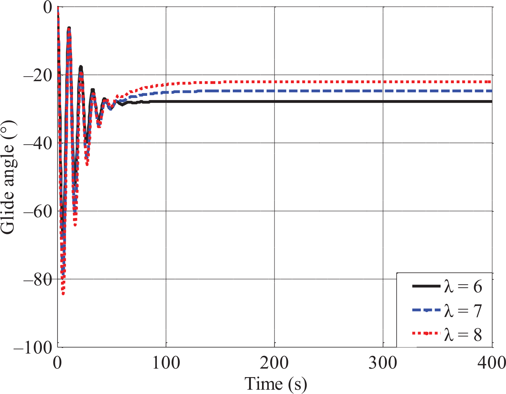
Glide motion, flight efficiency, and sweep angle
Figures 9 and 10 show that there is an optimal sweep angle to make the glide angle smallest. Figure 11 is the glide angle with different sweep angles. Figure 11 shows that when the sweep angle is 26°, the glide angle is the smallest and the glider has the best flight efficiency.

Glide motion simulation with different sweep angles.

Glide angle simulation with different sweep angles.
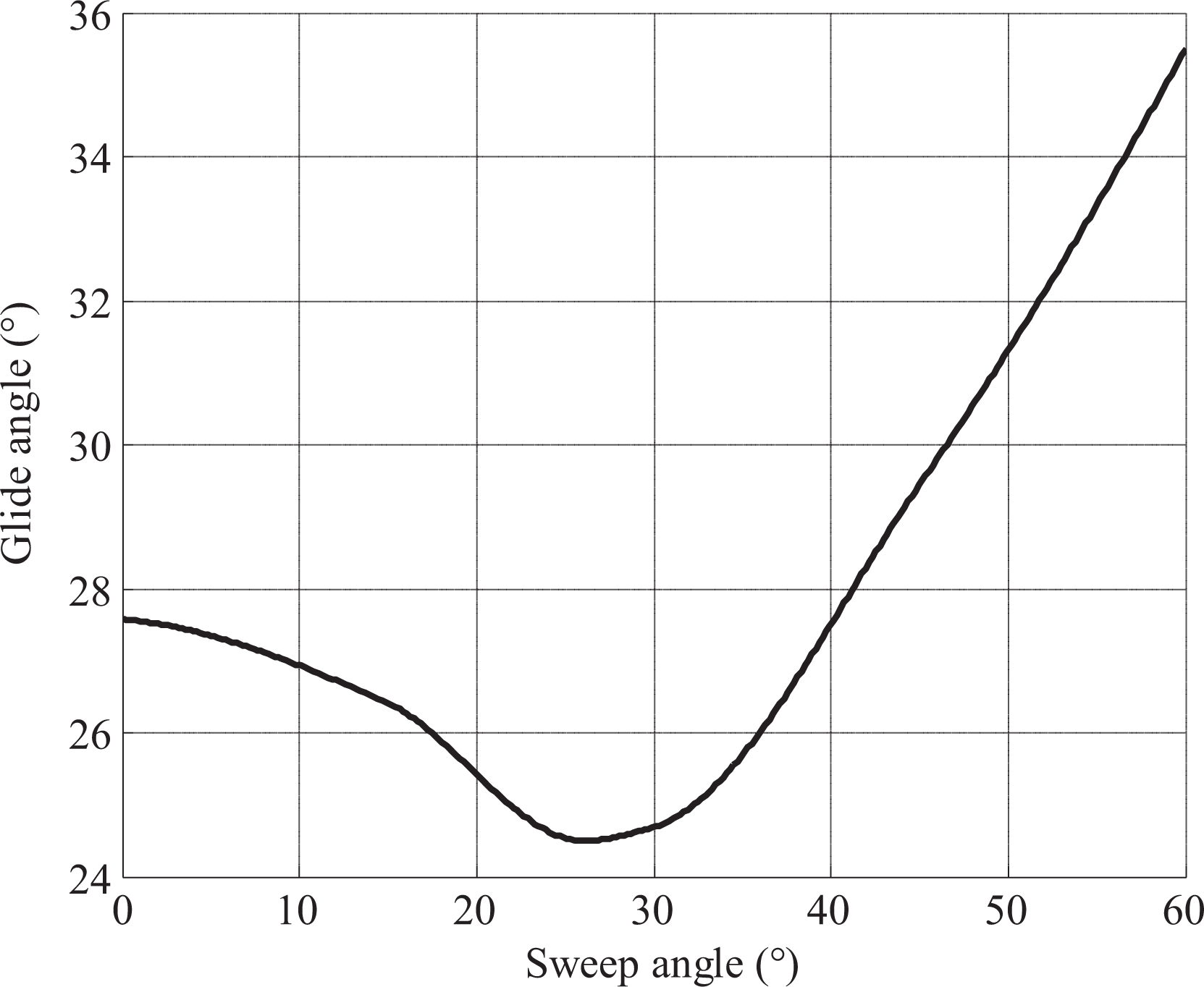
Relation between sweep angles and glide angles.
Spiral motion, maneuverability, and opposite AOA
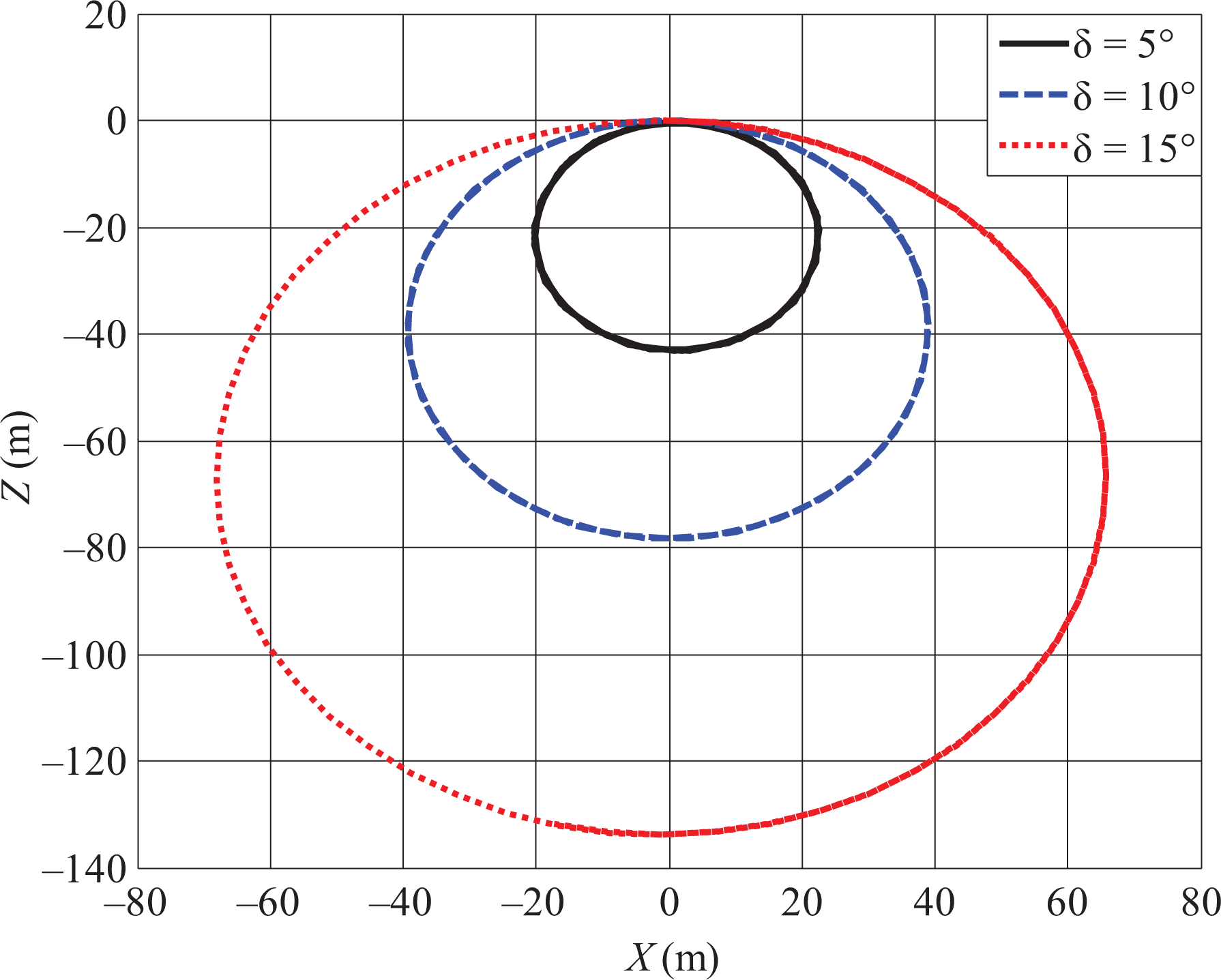
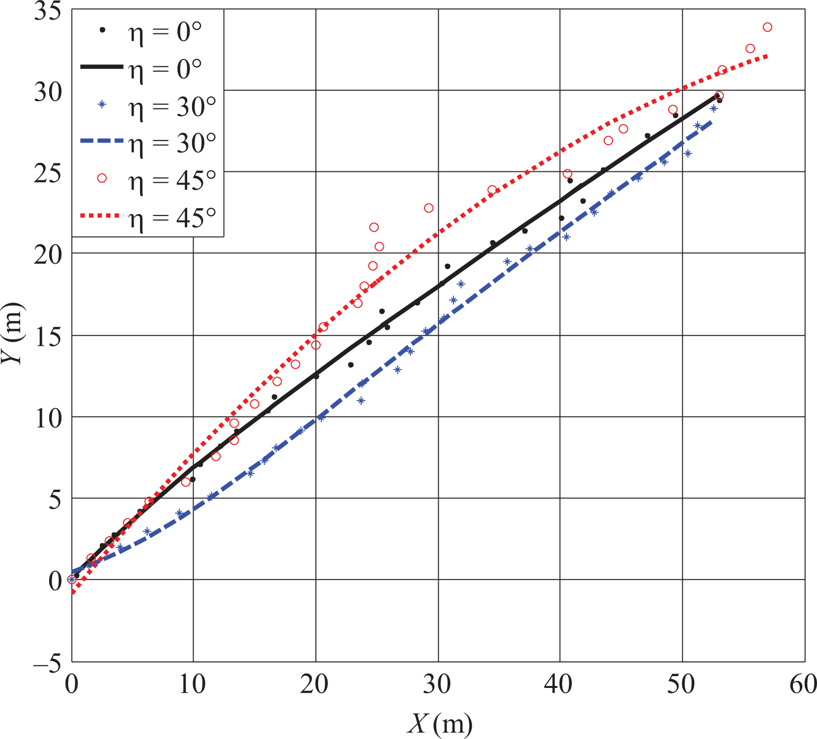
Petrel II with controllable wings can change directions by rotating the two wings in opposite directions. Figure 12 shows that the turning diameters are 50 m, 80 m, and 130 m with different opposite AOAs of ±5°, ±10°, and ±15°, respectively. Figure 13 shows that the sideslip angles are 26°, 19°, and 9°, respectively, which agrees with Figure 12. It can be concluded that the opposite AOA of ±5° causes the smallest turning radius and best maneuverability.
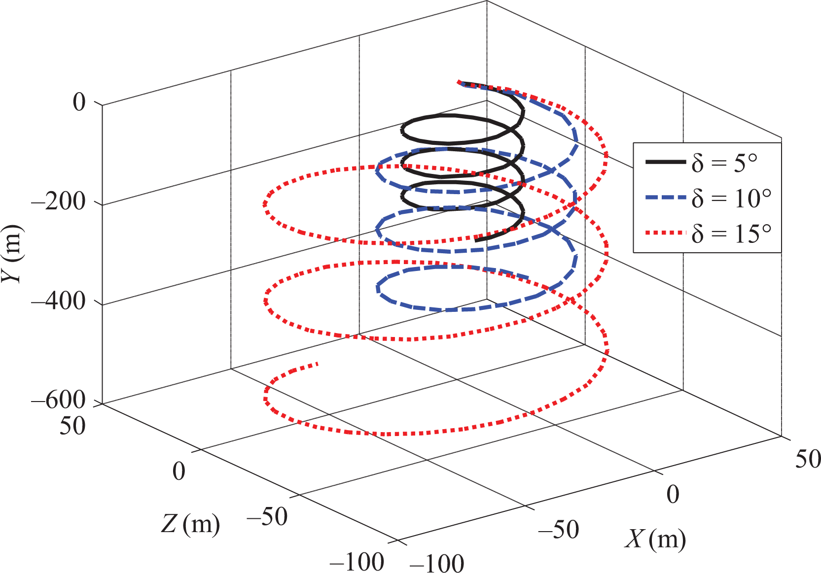
Spiral motion simulation with opposite AOA. AOA: angle of attack.
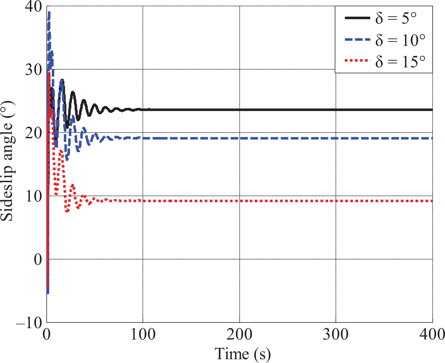
Sideslip angle simulation with opposite AOA. AOA: angle of attack.
Spiral motion, maneuverability, and aspect ratio
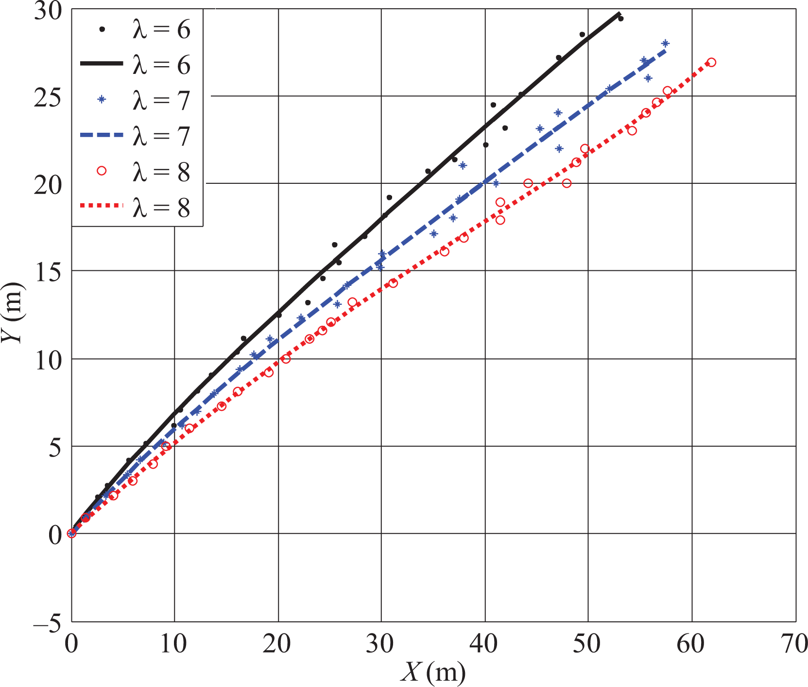
Figure 14 shows that the turning diameters are 90 m, 105 m, and 120 m with different aspect ratios of 6, 7, and 8, respectively. Figure 15 shows that the sideslip angles are 16°, 17°, and 19°, respectively, which agrees with Figure 14. It can be concluded that smaller aspect ratio causes smaller radius and better maneuverability.
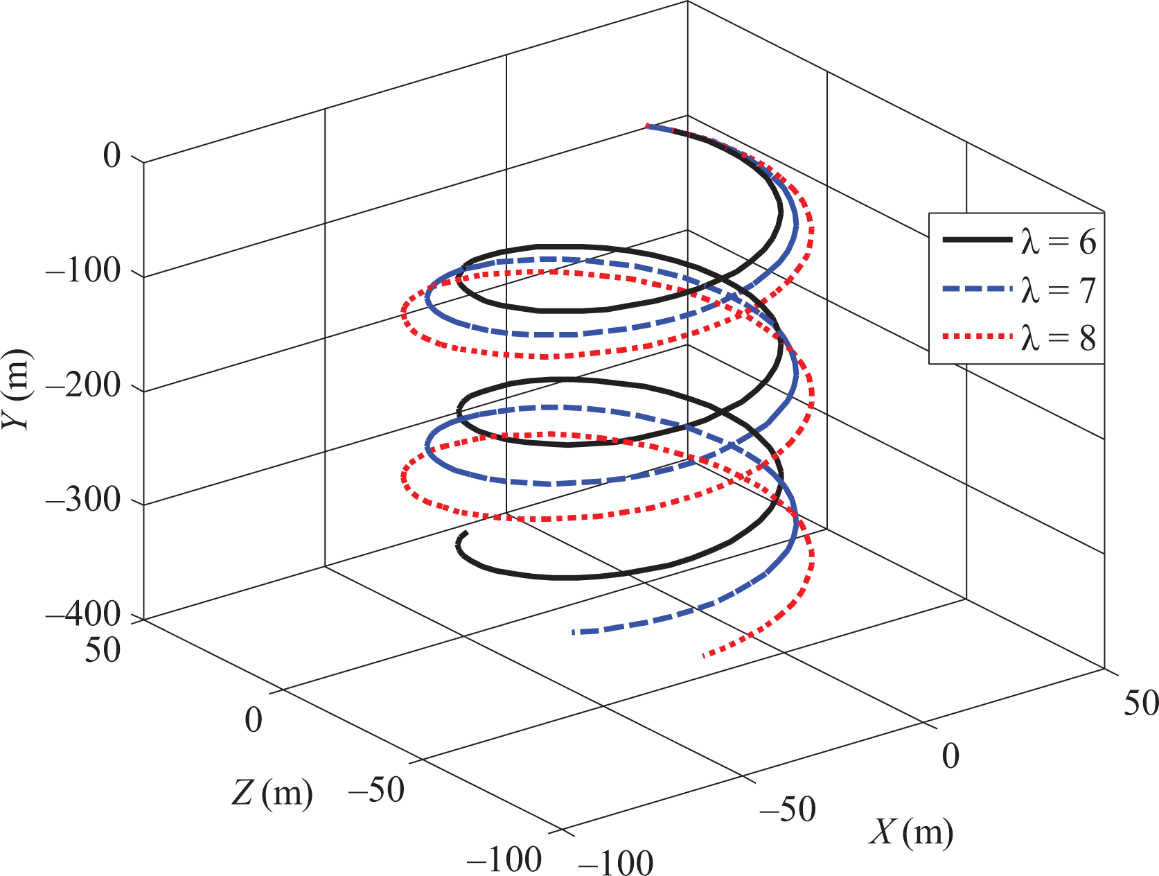
Spiral motion simulation with different aspect ratios.

Sideslip angle simulation with different aspect ratios.
Horizontal turning motion, maneuverability, and opposite AOA
Horizontal turning is completed by the propeller. Figure 16 shows that the turning diameters are 43 m, 79 m, and 134 m with different opposite AOAs of ±5°, ±10°, and ±15°, respectively. It can be concluded that the opposite AOA of ±5° causes the smallest turning radius and best maneuverability.
Horizontal turning simulation with different opposite AOAs. AOA: angle of attack.
Field trial
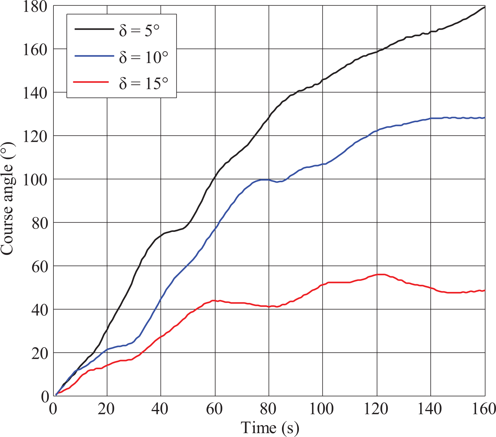
Field trials were conducted in Danjiangkou Reservoir, China. The radius of the trial area is over 1 km and the average depth is 40 m. Figure 17 shows that the HUG is changing direction in thrust mode. The pressure sensor gathers depth information. Electronic compass TCM3 gathers attitude information. Altimeter sensor guarantees that the glider won’t strike the bottom. The displacement of glider along X and Y axis can be derived from depth and attitude information. With the limitation of shallow water, the glider can’t finish complete spiral motion. The antenna mask can’t locate GPS location under water. Instead of turning radius, the change amount of course angle in the same time is used to evaluate the maneuverability. Figures 18 to 22 show the trial results.

Field trials in Danjiangkou Reservoir.
Glide motion trial with different aspect ratios.
Glide motion trial with different sweep angles.
Spiral motion trial with different opposite AOAs. AOA: angle of attack.

Spiral motion trial with different aspect ratios.

Horizontal turning trial with different opposite AOAs. AOA: angle of attack.
Glide motion
Figures 18 and 19 show that the trial results agree with those of the simulation. In glide motion, lager aspect ratio and the sweep angle of 26° can get better flight efficiency.
Spiral motion
Figure 20 shows that glider with opposite AOA of 5° has the largest course angle change of 179° in 160 s in spiral motion and better maneuverability. Figure 21 shows the glider with aspect ratio of 6 has the largest course angle change of 81° in 160 s and better maneuverability.
One thing to note here is that glider with opposite AOA of 15° loses the turning capacity at the depth of 18 m in Figure 20. The reason is that AOA of ±15 is beyond the stalling angle that affects the turning capacity of the glider. In this case, the hydrodynamic forces acting on the glider change. Theoretical equations cannot explain the stalling phenomenon. Therefore, simulation results do not reflect this phenomenon.
Horizontal turning motion
Figure 22 shows that the glider with opposite AOA of 5° turns a circle with the least time of 137 s and has better maneuverability.
Conclusions and future work
HUG Petrel II has three motion modes, including buoyancy driven glide, buoyancy driven spiral turning, and propeller driven level-flight, which require different wing configurations to achieve optimal flight performance. In this article, controllable wings are designed based on linkage synthesis to change AOA, sweep angle, and aspect ratio. Kinematics and dynamics models are established based on multibody dynamics, which treats components separately and is good for analysis of controllable wings. Finally, the impact of wing configurations on flight efficiency in glide motion and maneuverability in spiral motion and horizontal turning motion is investigated by Matlab (Matlab2010a) simulation and field trials. The conclusions are listed as follows: Glide motion, which puts long endurance and duration in the first place, values flight efficiency. Larger aspect ratio of 8 and the sweep angle of 26° should be realized to get smaller glide angle and better efficiency. Spiral motion values maneuverability. The opposite AOA of 5° and smaller aspect ratio of 6 should be realized to get smaller turning radius and better maneuverability. Horizontal turning focuses on maneuverability. The opposite AOA should be realized to get smaller turning radius and better maneuverability.
There is some work to be done in the future. In simulations and field trials of both spiral motion and horizontal turning motion, the opposite AoA of 5° shows the best maneuverability compared with 10° and 15°. The optimal opposite AoA between 1° and 10° should be determined in the future. Moreover, this article only explores the effect of each single parameter of the wings on flight performance. Orthogonal test of all factors, including AoA, sweep angle, and aspect ratio, should be conducted to determine the optimal wing configurations for various motion modes. In addition, the mechanism and cabin increase the complexity of system, so field experiment of long duration and distance should be conducted to justify the advantage of adding controllable wings.
Footnotes
Acknowledgement
The authors gratefully acknowledge the contributions of former and current members in the R&D team.
Declaration of conflicting interests
The author(s) disclosed receipt of the following financial support for the research, authorship, and/or publication of this article:
Funding
The author(s) disclosed receipt of the following financial support for the research, authorship, and/or publication of this article: This research is supported by the National Natural Science Foundation of China (nos 51475319 and 51575376) and the National Key Research and Development Program of China (nos 2016YFC0301101 and 2016ZX05057005).
Appendix
The videos describing the motions in system design section are available online (https://www.youtube.com/dashboard?o=U).