
Abstract
In this article, a design and analysis on 200-m-class hybrid underwater glider actuated by a buoyancy engine and a thruster was studied. The hull shape of the hybrid underwater glider was designed to reduce underwater resistance using Myring hull profile equations. A computational fluid dynamics analysis was conducted, and a resistance coefficient similar to that of existing underwater vehicle was calculated such that simulation reliability was verified. The relationship between the control value of the ballast discharged by the buoyancy engine and the velocity of a glider according to the path angle was analyzed. Through the analysis, the relationship between the optimal glide angle and the designed control value of the ballast water was drawn, and using this relationship, the optimal glider velocity was estimated. Also, the velocity of the hybrid underwater glider using the thruster only was measured through an experiment. Using both the thruster and ballast water control, it was shown that the maximum velocity of the developed hybrid underwater glider is over 2.4 knots.
Keywords
Introduction
In the past few years, underwater gliders (UGs) are widely used in oceanographic research.1–4 UGs can navigate changing the ballast water amount in the buoyancy engine periodically such that it has a good merit of using very small energy.5–7 UGs have an excellent endurance up to a few months or more. 8 In this reason, the UGs usually follow a sawtooth trajectory in the vertical plane. However, UGs can operate only a few weeks.9,10
The dynamic models of UGs including the mass shifter motion were set up by a number of researchers such as Graver and Leonard, 11 Bhatta and Leonard, 12 and Isa and Arshad. 13 Graver and Leonard 11 analyzed the stability of the sawtooth gliding motion based on a model-based feedback control method.
To take good high-speed merits of autonomous underwater vehicles (AUV), the thruster can be applied to the UG, which is called the hybrid underwater glider (HUG). The HUG can navigate using thruster, buoyancy engine, or hybrid thruster and the buoyancy engine. 14 Through the hybrid motion, HUG can obtain a faster velocity and can navigate along line trajectory.
So far, most of the research papers presented simulation results based on the dynamic model. Also, the maximum horizontal velocity of all the developed commercial UGs is less than 2 knots such that they may be inappropriate for tracking the path or targeting desired goals in the regions of fast currents. So, a high-velocity UG is needed for tracking the path under fast currents, and experimental researches are required for real application.
In this article, we first introduce the design and analysis of the hull for the HUG. In the “Mathematical model and motion simulation of the HUG” section, we conduct motion simulation through hull modeling of the HUG. In the “Driving performance experiment” section, we introduce the experiment on the self-propulsion of HUG, and finally, we present a summary and conclusion.
Design and analysis of the hull
Configuration of internal equipment
Figure 1 shows the cross-sectional configuration of the HUG designed in this article. Figure 2 shows the specifications of the external shape of the hull. The equipment installed inside the hull is largely composed of a buoyancy controller, an attitude controller, a battery, a control board, a thruster, a rudder, an external sensor, a Global Positioning System/communication antenna, and a fathometer. Each component is embedded in the circular cylinder hull.
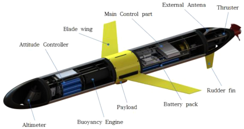
Cross-sectional configuration of HUG.

Exterior dimension of HUG.
Hull shape design
In the design of the external shape of the HUG, the hull shape of the bow and stern was designed using equations (1) and (2), which are Myring hull profile equations, 15 empirical equations that can minimize fluid resistance. Figure 3 shows the shape of the hull according to the myring hull profile equations.


Hull shape design using Myring equation.
Analysis of hull resistance
The glider designed in this article has a cylindrical hull having the blade wings with a sweep angle of 25° and the elliptical-shaped bow and stern. The hull resistance was analyzed using the computational fluid dynamics (CFD) scheme, and the shear stress transport k-omega turbulence model was applied to the simulation. The simulation was made for variable fluid velocities from 0.5 to 3 knots. Figure 4 shows the distribution of the fluid velocity around the glider, and the fluid velocity decreases around the nose and the curvature of the thruster. Figure 4(a) shows the hull from above, and Figure 4(b) is from the side of the hull.

Velocity distribution.
Figure 5 shows the pressure distribution along the longitudinal direction of the hull body model. The pressure in the rear is not even, possibly because of the surface resistance of the hull and the vortex generated by the wing blades on the center of the hull and by the thruster.
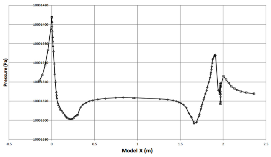
Pressure distribution along the longitudinal direction.
Figure 6 shows the simulation results of the fluid drag force for the velocity variance. According to this, resistance increases nonlinearly with respect to velocity increase. Also, the average drag force coefficient calculated from the simulated drag forces is 0.28, which is quite similar to 0.3 which is the drag force.
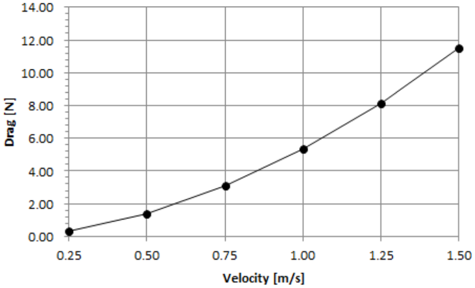
Drag force versus velocity.
Analysis of the maximum velocity
The ratio of the lift force to the drag force generated by the angle of attack (AoA) of the gliding glider affects the pitch attitude stability of the glider, as shown in Figure 7.

Action of lift and drag force.
To identify the lift force and the drag force according to the change in the AoA of the glider, a simulation was made about the lift and drag force with respect to the AoA ranging from 0° to 10°.
Figure 8 shows the coefficients of the lift force to the drag force according to the AoA. In the case where the AoA increases from 0° to 10°, the lift force increases remarkably compared with the drag force. In this article, the results of the relation between the lift force and the drag force are used to optimize the performance of the gliding of the glide.

Simulated lift and drag coefficients.
The path angle of the glider according to the ratio of the lift force to the drag force can be expressed in equation (3)

Figure 9 represents the relationship between the AoA and the path angle according to the calculated coefficients.

Relationship between the angle of attack and path angle.
The relationship between
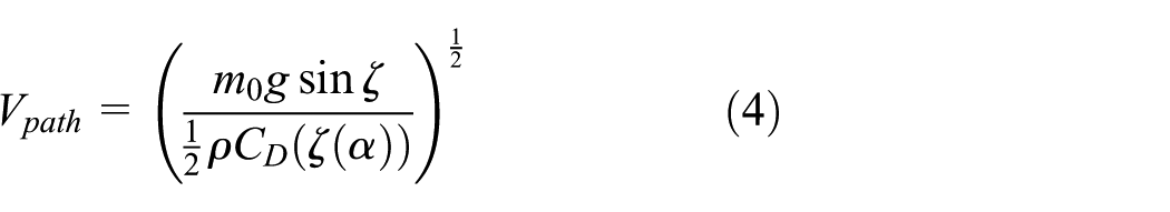


In equation (4), the angle where the horizontal velocity

Glider velocity versus path angle.

According to the simulation result in Figure 11, the maximum velocity of the glider according to the control value of the ballast can be expressed by equation (7)
Figure 12 shows the relationship between the displacement and the maximum velocity according to the ballast control ratio
Maximum velocity versus volume.
By using equation (7), the graph relating the maximum velocity and the ballast weight of the buoyancy engine is shown in Figure 13. The weight of the UG designed in this article is 50 kgf. For the case where the desired maximum velocity is 1.5 knots, the weight of the ballast water of the buoyancy engine of the UG is decided to be 0.45 kgf.

Maximum velocity versus ballast water weight.
Mathematical model and motion simulation of the HUG
Structure of UG system
The picture of the developed HUG is shown in Figure 14. The total weight of the HUG is about 50.5 kg, the diameter of the hull is 220 mm, and the total length is 1970 mm. The structure of the UG is composed of the stern, hull, and bow, as shown in Figure 15. The hull containing the buoyancy engine, mass shifter moving the internal battery, control board, and communication device is designed as a cylindrical shape to reduce the water resistance. Especially, the buoyancy engine (Figure 16), which is driven by the electric motor, was designed to place at the middle section of the hull to stabilize the pitching moment of the hull when the thruster is used. The advantage of the developed HUG is to control the velocity of the HUG using buoyancy engine and additional thruster such that the velocity of the HUG can be increased more than 2.4 knots. The specifications of HUG are shown in Table 1.

The picture of the developed HUG.
Cross-section of HUG.

Structure of the developed buoyancy engine.
Specifications of HUG.

HUG: hybrid underwater glider.
Mathematical model of HUG
A mathematical model for the UG is needed to design the controller for identifying dynamic characteristics of the UG that includes the motion of the internal mass shifter and buoyancy engine. First of all, the coordinates of 6-degree-of-freedom motion equations of the UG are described in Figure 17 in general. For the motion equations of the underwater vehicle, earth-fixed coordinate system EXYZ and body-fixed coordinate system Oxyz are set up. For the body-fixed coordinate system, moving direction of UG is put at x-axis, starboard direction at y-axis, and depth direction at z-axis. With the defined coordinates, translational motion and rotational motion of the UG are expressed in equation (8), according to Newton’s second law 16

Coordinate frame of underwater glider.
In equation (8), u, v, w and p, q, r represent the glider’s angular velocity of translational and rotational motion for the axes x, y, z, respectively.
The buoyancy engine changes the mass center and buoyancy center of the HUG, and the mass shifter changes the mass moment of inertia by control. The equations of the mass shifter for AUV are previously analyzed, 17 and similarly, related equations of the buoyancy engine and mass shifter of the glider are modeled as


To estimate the hydrostatic coefficient of external force term, hydrodynamic coefficients should reflect the influences of a change in the buoyancy of the ship hull and can be expressed in the following equations. The hull shape of the designed UG can be expressed using the empirical method 18


In equations (11) and (12),


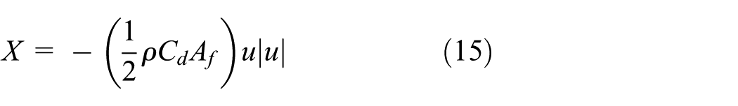
When a drag force according to the translational motion forward of a glider is expressed as equation (15), an axial drag force can be expressed by equation (16) in consideration of only a change in velocity

Inertial hydrodynamic forces
Added mass indicates the extent of an impact acting on underwater vehicle with an acceleration and can be induced using experimental or theoretical methods such as Planar Motion Mechanism (PMM). In the case of a relatively small underwater robot, the value to be measured by an experimental method is affected by the noise of a sensor or the environment, and thus, the reliability of the coefficient may be insufficient. In this article, an added mass coefficient is calculated as follows, based on existing empirical equations.
An added mass force acting on an object moving with 6 degree-of-freedom under the assumption of ideal fluid is expressed as follows 19


where
Hydrodynamic control forces
When a thruster is working, the following propulsive coefficient should be considered. Each coefficient is expressed by the components of external force acting on the axial direction of the hull and the slant components according to rotary torque


Control hydrodynamic forces are external forces generated by the change in momentum according to the operation of the rudder of a glider at sea and the change in the AoA of blades caused by the change in the center of gravity according to the operation of an attitude controller.
Considering a lift generated by the main wings and hull shape, equation (21) is drawn

and a proportional relationship for velocity is expressed by equation (22)

where
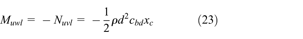
where xc indicates the distance between the center of rotation according to the rotation of the hull and the geometric center.
If all coefficients modeled above are substituted for external force components, the equations of motion of a UG including external force term are expressed by equation (24)
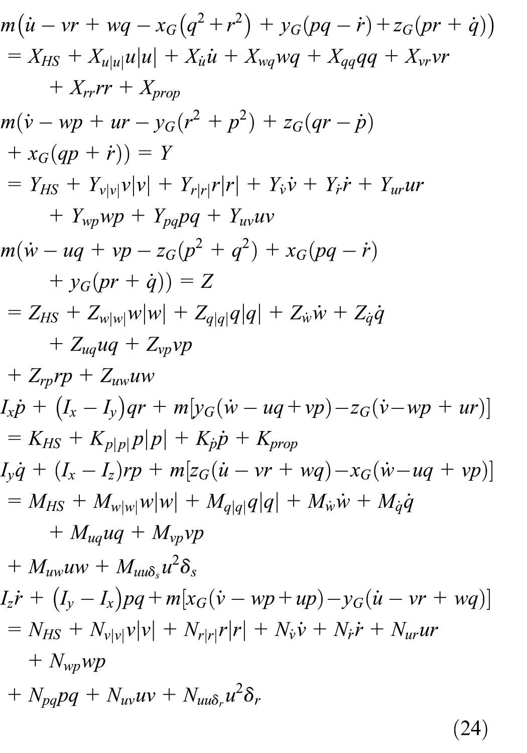
where the center of mass


If equations (25) to (27) are applied to 6-degree-of-freedom equations of motion, the underwater motion of a glider according to an internal moving mass and buoyancy control can be analyzed. 21
Simulation of maximum velocity
Table 2 shows the maximum velocity according to the path angle due to ballast control of the buoyancy engine of the HUG and the sailing distance according to one-cycle underwater navigation and uplift. The path angle was changed from 35° to 20° on a case-by-case basis. At this time, the location at the time of uplift can be predicted based on the change of the AoA and the change of the gliding distance.
Velocity and cycle distance by glide angle.

Driving performance experiment
An experiment was conducted to verify the performance of more than 2.4 knots when the buoyancy engine and the thruster of the developed HUG are simultaneously applied.
Measurement test of thruster propulsion
An experiment was conducted in a water tank of 50 m long, 15 m wide, and 10 m deep to measure the velocity when the thruster installed at the rear of the HUG was propelling. Figure 18(a) represents that the HUG starts a navigation at the starting point of the water tank along the longitudinal direction, and the velocity is measured using Doppler Velocity Logger (DVL) installed at the center of the hull. Figure 18(b) shows the HUG driving in water.

Velocity test using thruster.
To measure the velocity of the HUG propelled by the thruster only, the thruster of the HUG ran for 30 s and the velocity experiment results are shown in Figure 19, where the solid line represents the velocity of the HUG along x-axis. Sampling time was 0.03 s. In the experiment, the input voltage for the thruster was regulated to have the 500 r/min which is 25% of the maximum revolutions per minute, 2000 r/min of the thruster. Under this condition, it was found that the velocity of the HUG along x-axis reached 0.46 m/s after 10 s.
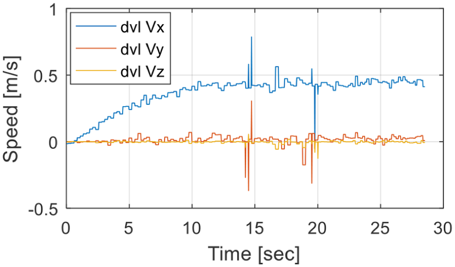
Velocity using thruster.
Conclusion
In this article, a design and analysis on a new HUG actuated by a buoyancy engine and a thruster was conducted. The external shape of the HUG hull was designed using Myring hull profile equations to reduce underwater resistance, and a CFD analysis was conducted to find a resistance coefficient for the designed external shape of the hull. Through the analysis, a resistance coefficient similar with that of an existing underwater vehicle was calculated such that simulation reliability was secured.
The relationship between the optimal glide angle and the designed control value of the ballast water of 0.45 kgf was drawn through analyses, and using this relationship, the optimal glide angle of 35° was calculated. Based on these, the maximum horizontal velocity of 1.5 knots was induced through the simulation.
As a result of the simulation, the maximum horizontal velocity of the HUG is 1.5 knots without using the propeller. For measuring the speed of the HUG actuated by the propeller only, an experiment was performed. As a result of the experiment, the velocity of the HUG is measured as 0.9 knots by using the propeller only with 25% of propelling force. When both of the propeller and buoyancy engine are applied, the added speed would be 2.4 knots. By using both propeller and buoyancy engines, the maximum velocity is estimated to be much higher than 2.4 knots when the propeller is fully actuated using the buoyancy engine.
Footnotes
Handling Editor: Wen-Hsiang Hsieh
Declaration of conflicting interests
The author(s) declared no potential conflicts of interest with respect to the research, authorship, and/or publication of this article.
Funding
The author(s) disclosed receipt of the following financial support for the research, authorship, and/or publication of this article: This research was supported by Unmanned Vehicles Advanced Core Technology Research and Development Program through the Unmanned Vehicle Advanced Research Center funded by the Ministry of Science, ICT and Future Planning, the Republic of Korea (No. 2016M1B3A1A 02937626), and this research is a part of the project National Research Foundation of Korea (NRF-2016R1A2B4011875).