
Abstract
An insect-type flapping wing micro aerial vehicle offers high aerodynamic efficiency and maneuverability in confined spaces. The complicated aerodynamic/structural behavior of flapping wing micro aerial vehicle, however, causes difficulties regarding the dynamic control and parametric design. This paper develops a moderately accurate numerical framework taking into account the passive motion of the main wings. Finite-element-based multibody dynamics and two-dimensional unsteady aerodynamics are combined to simulate the hover of a flapping wing micro aerial vehicle. In addition, flexible and rigid wings are compared through numerical simulation considering the flexibility. In terms of the average thrust, numerical simulation by fluid–structure interaction shows good agreements against the experimental results within 5% discrepancy.
Keywords
Introduction
In nature, birds or insects use flexible wings and muscles to generate aerodynamic forces and maneuvering capability. The birds use their tail wings for altitude stabilization heading angle control. On the other hand, insects use their two wings only for stable flight and posture change. A large number of studies have been conducted to mimic these behaviors and improve aerodynamic efficiency and maneuverability.1–6 An insect-type flapping wing micro aerial vehicle (FWMAV) uses two main wings only to generate the aerodynamic forces and control moments, such as rolling, pitching, and yawing. Because of these features, an insect-type FWMAV may be fabricated in a compact size and smaller weight compared to the bird type. The small size and hover capability enable an insect-type FWMAV to freely maneuver and take off in a confined space. The insect-type FWMAV can be employed for various missions in the military and civilian fields, such as reconnaissance, video surveillance, and rescue missions. However, some features of insect-type FWMAVs, such as large flapping frequency and smaller weight, produce oscillatory motion and consequently result in degraded flight stability. In addition, iterative fabrication and design of the insect-type FWMAV to improve its stability will be a challenging task due to its small size that requires sophisticated design and hardware validation. Therefore, the simulation of the flapping motion and prediction of the aerodynamic load are important for developing an FWMAV at the design stage.
The insect-type FWMAV is designed with a combination of two mechanisms. The first is the flapping mechanism. Gong et al. 7 designed a string mechanism and modularized flapping mechanism to generate effective flapping motion. They conducted a parametric study regarding the specifications of a cam and string for their optimal mutual kinematics. Mateti et al. 8 used the epoxy-based negative photoresist dry film to develop a simple flapping mechanism using a lesser number of components. This mechanism adopted two unique piezoelectric actuators and flexible hinges. Secondly, an insect-type FWMAV requires the capability of generating not only the thrust and side force, but also the control moments using the main wings only. Various ideas paved the way for an improved control mechanism of the tailless flapping wings, such as the varying shape of the wings, stroke plane, or the unequal flapping frequencies of the two wings. Phan et al. 9 designed an insect-type FWMAV, named KUBeetle, which employed the trailing edge control device to generate the control moments. They also fabricated a prototype and measured the control moments to verify its maneuverability. Another example of the control mechanism was the NUS-Robotic bird, designed by Nguyen and Chan. 10 It employed four wings whose control mechanism was composed of wing stroke plane modulation. Two motors were configured to modulate the stroke plane for rolling, and two actuators were used for pitching and yawing.
Numerical simulations of the insect-type FWMAV have been conducted in previous research studies regarding the flight principle of flapping wings and flapping aerodynamics. Cho et al. 11 established a computational framework regarding the three-dimensional fluid–structure interaction (FSI) of the flapping wing. They coupled a preconditioned Navier–Stokes equation and a co-rotational (CR) beam/shell analysis to simulate a flapping wing. Yoon et al. 12 studied the characteristics of the camber effects of the flapping wing of the aforementioned design. They employed the unsteady three-dimensional Navier–Stokes equation and adopted the nonlinear finite-element method based on the CR formulation. The results were compared with the experimental results. Hassan and Taha 13 performed a numerical simulation for the hover of an insect-type flapping wing. They examined the aerodynamic–dynamic interactions to identify the relationship between fast, periodic wing aerodynamic forces, and relatively slow body motion. They found an oscillatory stabilization mechanism that contributed to the body pitching stabilization. Flappy Hummingbird, an open-source dynamic simulation, was developed by Fei et al. 14 They used different flapping frequencies for both wings to produce an asymmetric force. The blade element theory and quasi-steady aerodynamic model were adopted to simulate take-off and altitude tracking. They also constructed a simple proportional integrated derivative (PID) flight controller based on the simulation results.
The flexibility of the FWMAV wing affects the propulsive efficiency with regard to the thrust and power input.15–17 Heathcote et al. 18 conducted a study on the variation in wing propulsion in terms of the spanwise flexibility. Water tunnel tests were conducted on rigid, flexible, and highly flexible wings. It was confirmed that the flexible wings generated a larger thrust coefficient and required less power input compared to the rigid wing. However, in the case of a highly flexible wing, an increased phase delay was found at the wingtip, and a significant decrease in thrust was observed. Therefore, it is important to consider flexibility for a more accurate numerical simulation of the FWMAV.
In this paper, a numerical simulation of the FWMAV is conducted by using the combinations of finite-element-based flexible multibody dynamics and two-dimensional unsteady aerodynamics. Flapping/control mechanisms are designed, and simplified multibody elements are employed to represent complicated motions of the FWMAV. For the numerical simulation, aerodynamic loads can be estimated by a predictive model for the aerodynamic coefficient19,20 and the two-dimensional unsteady aerodynamics suggested by Peters et al. 21 and Peters. 22 Also, ground tests are performed for the thrust validation of the numerical model. To confirm the flexibility effect of the FWMAV wing, thrust is to be compared between the wings composed of rigid elements and flexible beam elements. During the flapping motion, a local deformation is detected in the flexible wing, and the estimated thrust result is compared with the experimental data. After the validation, the present numerical framework is applied to the examination of the FWMAV design.
Compared to fully three-dimensional FSI analysis, the geometrically exact beam formulated wing enables quick modifications to the geometry variables or analysis environment. These advantages will be applicable to future studies such as geometry and material optimization of the wing configuration and meta-model generation for the controller design.
Mechanisms of the FWMAV
In this section, the design mechanisms of the FWMAV will be described from two aspects: flapping and control. To design an effective insect-type FWMAV, a flapping and control mechanism will be required to generate thrust, and change the FWMAV posture. This study adopts a gear mechanism for the flapping motion and uses a trailing edge control method to enable maneuvering capability.
Flapping mechanism
Among the various methods used for generating the flapping motion, the current paper will employ a gear mechanism. This method will use a single DC motor for operation, and the torque of the motor will be transmitted to the main wings. The gear mechanism will use only the rotational motion of the gears, and the absence of linkages will allow the mechanism to be simple and intuitive. The specifications of the present gear mechanism are explained in Table 1. Figure 1 shows the overall configuration of the flapping mechanism. The gear mechanism, with a total weight of 10.2 g, operates at the flapping amplitude of

Configuration of the gear mechanism. (a) Isometric view. (b) Top view.
Specifications of the flapping mechanism.

Control mechanism
Trailing edge control is adopted for generating the control moments.9,23 This method will turn the two connecting rods at the root of the wing, twisting the trailing edges of the left and right wings. Therefore, the surface of the wing will loosen and tighten depending on the rotating direction and radius of the connecting rod, as shown in Figure 2. Then, the surface will be stretched by aerodynamic pressure during the flapping stroke. In this manner, the twist angle of both wings will change during the up and down strokes, and a control moment is produced due to asymmetrically distributed aerodynamic loads.

Geometry of the wings regarding the connecting rod rotation. 24 (a) The wing surface with reference to the positive rotation of the connecting rod. (b) The wing surface with reference to the intermediate state. (c) The wing surface with reference to the negative rotation of the connecting rod.
The configurations and specifications are depicted in Figure 3(a) and Table 2. The total weight and operating radii in terms of the control inputs, pitching, rolling, and yawing are designed to be 9.1 g and

Configuration of the trailing edge control mechanism. (a) Isometric view. (b) Top view.
Specifications of the control mechanism.

Figure 4 shows the behavior of the present control mechanism. In the figure, the blue lines indicate the connecting rods that twist both wings. As shown in Figure 4(a), the connecting rods rotate in the same direction as the

Present trailing edge control. (a) Pitching moment generated due to the wing twist modulation. (b) Rolling moment generated due to the wing twist modulation. (c) Yawing moment generated due to the wing twist modulation.
Numerical simulation
Flexible multibody dynamics analysis is a challenging task due to the geometric nonlinearities of the flexible components combined with the rigid body dynamics. Thus, iteration techniques are required to solve nonlinearities in the analysis of flexible multibody dynamics. To simulate the flapping stroke, finite-element-based multibody dynamic analysis, DYMORE, will be adopted. 25 DYMORE has been utilized in the analysis of the rotary-wing. The present paper proposes a suitable modeling for the simulation of an insect-type flapping wing using DYMORE.
For the numerical simulation, FSI is considered. The schematics are shown in Figure 5. In this paper, the air station is distributed spanwise at the 25% chord position. Also, the location of the air station can be selected using the prescribed chord length data. Using the structural dynamics, the displacement and velocity can be obtained with the prescribed initial conditions. After that, the updated displacement and velocity results are applied to the air station to re-estimate aerodynamic loads. The resultant forces and moments are then applied back to the structural model to extract the displacement and velocity.
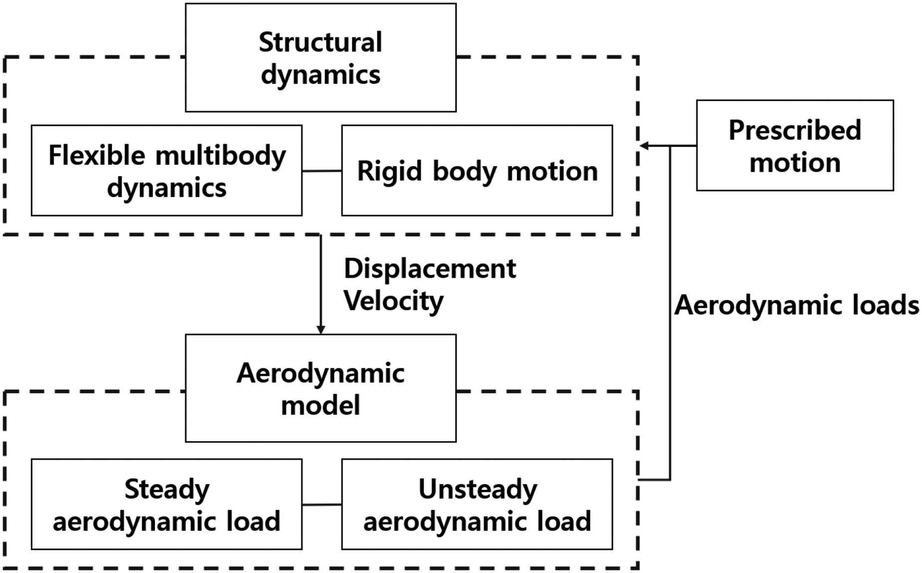
Schematic diagram of the analytical framework.
Simulation setup
In this paper, a 4.12 aspect ratio wing is used to generate the aerodynamic force. Figure 6 shows the configuration of the main wing. The carbon rod of 1 mm diameter is located at the leading edge to intertwine the wings to the fuselage. The wing surface is made of polyester (Oracover, LANITZ Co., Germany). In addition, as shown in Figure 7, the polyester used for the material of the main wing is wrapped around the leading edge to generate the angle of attack effectively during flapping. The veins made of carbon sheet, which are arranged on the wing surface, play a role to maintain the desired wing shape during the flapping stroke. The additional wing surface is designed at a wing incidence angle of 20

Configuration of the main wing.

Connectivity of leading-edge and main wing.
Structural model
Figure 8 shows a schematic diagram of the DYMORE input configuration. The fuselage and flapping mechanism are represented by the rigid bodies and multiple joint elements. Flapping joints are adopted at the root of the wings to simulate the flapping stroke, and the sinusoidal motion is prescribed upon both wings simultaneously. The wing rotates freely at its leading edge and the constraint elements are used to simulate a passive rotation of the wing. The detailed configuration of the wing to simulate such behavior is shown in Figure 9. The two bodies represent the beam elements of the leading edge and the main wing, respectively. The node of the main wing and that of the leading edge are placed at the same location. There are four kinematic constraints to interconnect the leading edge and the main wing under the relative rotation.
26
Also, to enforce the holonomic constraints, the Lagrange multiplier is adopted. Equation (1) is the constraint for the relative displacement of two bodies. Equations (2) and (3) are the constraints in the relative rotation. Equation (4) provides the constraint for defining the relative rotation.


Schematic of the present multibody representation.

Coordinates and kinematic constraints of the multi-components.
The superscripts
To consider the flexibility of the wing, the one-dimensional displacement-based geometrically exact beam element will be adopted. Figure 10 shows the geometry and coordinate systems of the beam. The origin of the reference axis is located at the pitching joint and the origin of the cross-section of the undeformed beam is placed on a reference axis. The axis

Geometry of the beam.
Also, variational asymptotic methods (VAM) based cross-sectional analysis, VABSTM and PreVABSTM, are adopted to conduct a two-dimensional cross-sectional analysis.27,28 The procedure of cross-sectional analysis is explained as follows. First, PreVABS, the preprocessor of the cross-section, generates a mesh. Then, VABS imports nodal and elemental information and analyzes the mass and stiffness distribution that is represented as the constitutive matrix. The sectional properties consist of one-dimensional generalized strain. And two-dimensional strain energy is minimized by the obtained generalized strain to deduce the warping function. Through the procedure, 6
The stiffness distribution of the wing can be obtained using the aforementioned procedure. For the numerical simulations, the main wing is discretized into 125 spanwise stations as shown in Figure 11. The regions of the wing stations are divided into large parts in accordance with the number of the included veins, and the cross-sections of each region are analyzed in their frame.
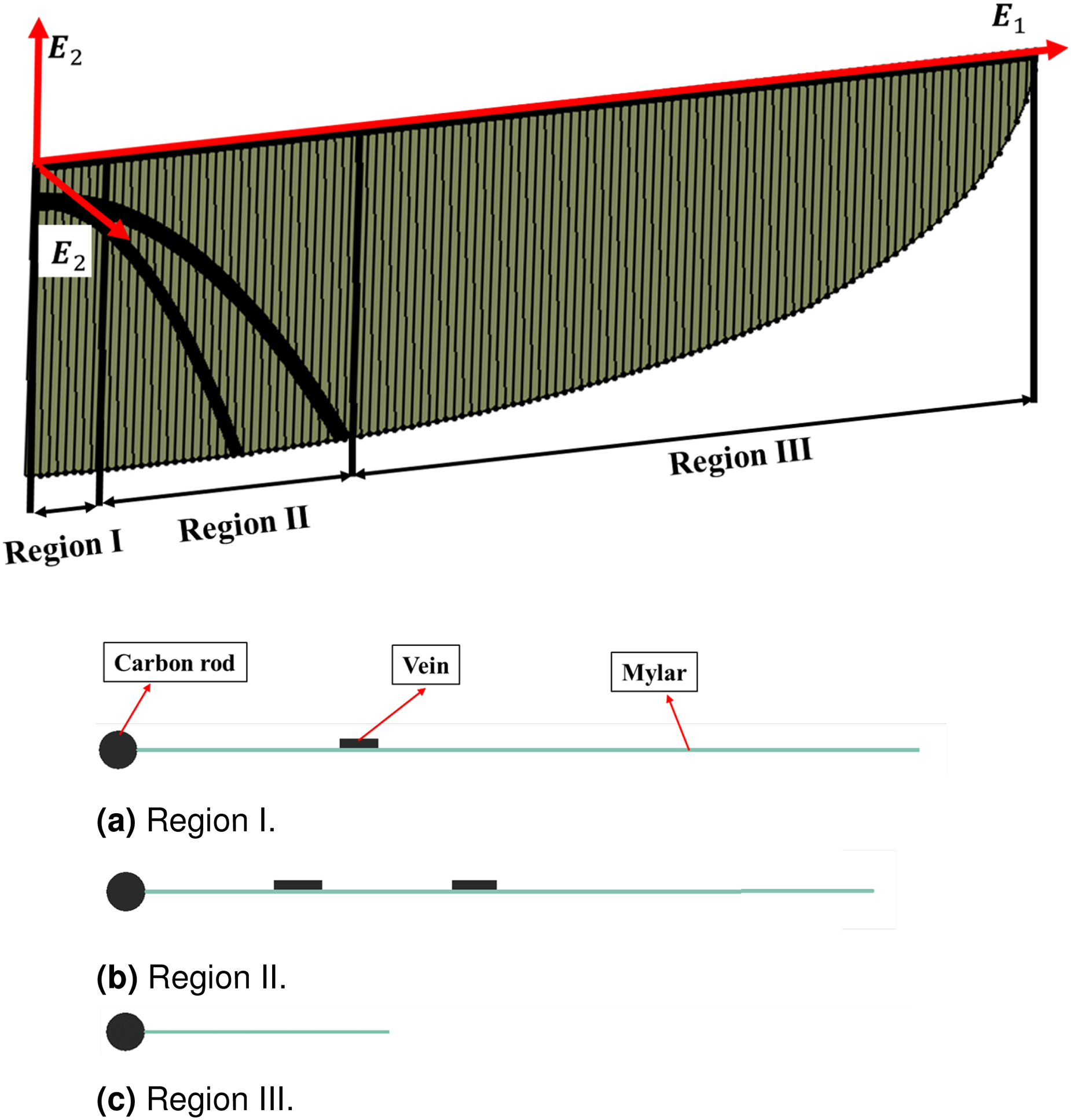
Schematic of the discretized wing. (a) Region I. (b) Region II. (c) Region III.
The cross-sectional area of the leading edge beam is constant along the span, and the bending stiffness is 9.81

Bending stiffness of the main wing (

Bending stiffness of the main wing (

Mass distribution of the main wing.
Aerodynamic model
The aerodynamic model of the wing provides the steady loads and unsteady loads, whereas the lift and drag coefficients of the steady component are obtained from the predictive model. Dickinson et al.
29
found that simple harmonic relationships exist between the angle of attack and the translational force including the effect of attached leading-edge vortex through mineral oil tank experiments. The formulations are shown in equations (6) and (7)


Aerodynamic coefficients. (a) Lift coefficients in terms of angle of attack. (b) Drag coefficients in terms of angle of attack.
This method solves the incompressible potential flow for an arbitrary wing motion in time. The unsteady aerodynamic loads are obtained by the nonpenetration boundary condition and small deformation assumption of the airfoil as shown in equations (12) to (14). The superscript u denotes the unsteady components:


Validation with ground experiment
The polyester membrane and the carbon vein of the main wings are fabricated by a laser cutting and a computer numerical control milling machine, respectively.
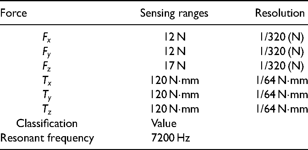
Overall schematics of the ground testbed are depicted in Figure 16. The hover thrust of the main wings is measured by a load cell (Nano 17, ATI Inc., USA). The specifications of the load cell are summarized in Table 3. The supporting fixture of epoxy fiberglass is machined to connect FWMAV and the load cell. The load cell is also stationed at the testbed of an aluminum profile. FWMAV is mounted at the top surface of the load cell. To embody a hover state, the twist angle of the connecting rod is fixed at 0

Overall configuration of the testbed.

High-speed camera recording of the FWMAV.
Specifications of the load cell.
The thrust comparison between the simulation and experiment is shown in Figure 18. The experiments show that the flapping frequency is 10.6 Hz. Moreover, the thrust data acquired in terms of the time history are filtered using the low pass filter with a cut-off frequency of 100 Hz. As a result, the time-average thrust is estimated as 12.8 gf.

Thrust history obtained by the experiment and numerical simulation.
The calculated thrust is 12.5 gf, which moderately corresponds to that by the measurements within a discrepancy of 2.4%.
Flexible wing versus rigid wing
The finite-element-based multibody dynamics model in this paper is capable of considering the flexibility of the wing and perform FSI analysis in consideration of local deformation. To evaluate the effect of flexibility, numerical simulations are performed on a rigid wing and flexible wing under identical frequency conditions. A rigid wing can be easily modeled by replacing the existing geometrically exact beam elements with rigid elements. For comparison, numerical simulation is performed at a flapping frequency of 14 Hz. The estimated thrust on a flexible wing is 23.05 gf and a rigid wing is 18.69 gf. Two results show a relatively large discrepancy of 19%. Figure 19 shows the displacement and angular velocity of the wingtip. For a rigid wing that does not account for flexibility, the tip displacement is zero and the angular velocity is obtained to be a single-phase sine wave. On the contrary, in the case of the flexible wing, changes in displacement are detected due to the aerodynamic load generated during the flapping motion. This results in a change in angular velocity. Depending on the displacement, two angular velocity maxima during the upward and downward strokes are illustrated in Figure 19. Therefore, as mentioned in the numerical simulation section, such updated displacement and velocity are reflected in the aerodynamic model to estimate the aerodynamic load, resulting in a relatively larger thrust output.

comparison between the flexible and rigid wing. (a) Tip displacement history obtained by the numerical simulation regarding the flexible and rigid wing. (b) Angular velocity history was obtained by the numerical simulation regarding the flexible and rigid wing.
To verify, experiments are conducted at different flapping frequencies between 9 and 13.5 Hz, and the results are compared with the numerical simulation. Figure 20(a) shows the thrust measurement and the prediction in terms of frequency. Both flexible and rigid wings show similar trends with the experiment. However, for all the sections, the thrust predictions for rigid wings are obtained to be smaller than those for flexible wings. The discrepancies are shown in Figure 20(b). Since the difference is within 5% in all the cases of the flexible wing, multibody dynamics modeling is considered to be adequate. However, in the case of the rigid wing, there exists a large discrepancy. Especially, the largest difference is observed in the 12th case that has the highest frequency because the effect of flexibility increases as the frequency increases.

Validation with ground experiment. (a) Comparison of experiment and numerical simulation (flexible and rigid wing). (b) Discrepancy of numerical simulation (flexible and rigid wing).
Implementation of the design procedures
As aforementioned, the present numerical framework produces an estimation of the aerodynamic loads that are obtained by experimental results. Such a simulation may substitute a sophisticated prototype experiment and the flight performance may be estimated in the design phase.
Weight estimation
Through the current numerical analysis, avionic parameters may be estimated for a variety of flight conditions. For instance, the target weight of the FWMAV will be evaluated through averaged thrust calculations for a climb in terms of the flapping frequencies as shown in Figure 21. Flapping frequencies vary from 12.5 to 15.5 Hz at intervals of 0.5 Hz, and the relevant thrust shows an increasing tendency. Through the series of processes, it is concluded that the current FWMAV, which is 23.2 g including the payload, may climb at flapping frequencies above 14 Hz.

Thrust history obtained by the experiment and numerical simulation.
Control force estimation
The present numerical framework is capable of simulating the control mechanism. The flapping and control mechanisms are modeled by simplifying the detailed configuration of the previously described device and by only implementing the operation principle. As shown in Figure 8, the connecting rod creates maneuverability by twisting the wings. For the sake of the modeling, rigid body elements are employed for the adjustment of the connecting rod and joint elements. The connectivity of the rigid element and the fuselage consists of three individual joints to implement rolling, pitching, and yawing motions. Each revolute joint is implemented by the kinematic constraints and the Lagrange multiplier as described in equations (1) to (4). In addition, by applying a prescribed motion to the revolute joint, which corresponds to control input, behavior similar to the control mechanism can be observed. Also, various types of control motion can be simultaneously generated.
These simulation setups, which are defined with the control mechanisms, estimate the distribution of the moment corresponding to rolling, pitching, and yawing motion. The control input consists of angles from 3

Thrust and control moments in terms of frequency and twist angle. (a) Rolling moment history in terms of twist angle for numerical simulation. (b) Pitching moment history in terms of twist angle for numerical simulation. (c) Yawing moment history in terms of twist angle for numerical simulation.
Conclusion
Despite the various merits of the FWMAV, its smaller size requires limited design parameters and a sophisticated fabrication process. Moreover, the unique design of the FWMAV requires an exclusive approach for the flapping simulation during the design phase of the vehicles and the controller.
In this paper, a numerical framework of the FWMAV is developed by the finite-element-based flexible multibody dynamic analysis and cross-sectional analysis, which consists of the geometrically exact beam, joints, and rigid body elements. The present numerical simulation is capable of considering wing flexibility, which affects aerodynamic performance. For numerical simulation, the two-dimensional unsteady aerodynamics suggested by Peters et al.
21
and Peters
22
is applied, and the aerodynamic coefficients of lift and drag, are obtained from the predictive model.19,20 Although the discrepancies occur at the time of the stoke change, admissible aerodynamic loads will be obtained in terms of the averaged values. A discrepancy of 2.4% is observed. The analysis reflecting the structural deformation is compared with the rigid element model. Also, the experimental results were compared under various frequencies conditions, and the flexible wing results show a discrepancy of
The present numerical analysis is implemented for the evaluation of the flapping/control mechanisms of the current FWMAV whose weight and the operating radius of the trailing edge are 23.2 g and
In the future, the current numerical framework will be applied to the design of PID controllers to obtain flight stability. Then, those controllers will be mounted on the FWMAV that will be fabricated for the free flight experiment.
Footnotes
Declaration of conflicting interests
The authors declared no potential conflicts of interest with respect to the research, authorship, and/or publication of this article.
Funding
The authors declared the following potential conflicts of interest with respect to the research, authorship, and/or publication of this article: This research was supported by a grant to Bio-Mimetic Robot Research Center Funded by Defense Acquisition Program Administration, and by Agency for Defense Development (UD190018ID).