
Abstract
How to determine the camera’s next best view is a challenging problem in vision field. A next best view approach is proposed based on occlusion information in a single depth image. First, the occlusion detection is accomplished for the depth image of visual object in current view to obtain the occlusion boundary and the nether adjacent boundary. Second, the external surface of occluded region is constructed and modeled according to the occlusion boundary and the nether adjacent boundary. Third, the observation direction, observation center point, and area information of external surface of occluded region are solved. And then, the set of candidate observation directions and the visual space of each candidate direction are determined. Finally, the next best view is achieved by solving the next best observation direction and camera’s observation position. The proposed approach does not need the prior knowledge of visual object or limit the camera position on a specially appointed surface. Experimental results demonstrate that the approach is feasible and effective.
Keywords
Introduction
The determination of next best view is always one of the important and difficult problems in many fields such as robot navigation, 3D reconstruction, automatic assembly, object recognition, spacecraft docking, and so on, which has attracted extensive attention of scholars. 1 –5
Nowadays, there are two main types of image information used to determine next best view, intensity information, 6 –8 and depth information. 9 –15 The methods based on intensity information are relatively fewer than the methods based on depth information. Compared with 2D intensity image, it is easier to obtain the 3D information of scene from 2.5D depth image; therefore, the existing next best view methods are usually achieved using depth image. Connolly, 9 as one of the earlier scholars studying next best view, adopted octree model to describe the visual object, and marked each node to determine next best view. But this method doesn’t consider occlusion factor, so for the visual object with occlusion phenomenon, the accuracy of this method can’t be ensured. Scott 10 proposed a method based on the modified measurability matrix (3 M) model to solve the viewpoint planning problem; however, this method needs the prior knowledge of scene. Banta et al. 11 proposed a method based on voxel information and overall observation strategy to determine next best view. This method not only needs the prior knowledge of scene, but also limits the camera position on a fixed surface. Li and Liu 12 proposed a viewpoint planning method by calculating information entropy and regarded the view corresponding to maximal information entropy as next best view, but the camera position is also limited on a fixed surface. Vasquez-Gomez at al. 13 proposed a method based on octree model and ray tracing to determine next best view. Krainin at al. 14 proposed a method based on the contour information of visual object to determine next best view. Zhang et al. 15 proposed a method based on visual servo to determine next best view. But methods in the literature 13 –15 all depend on specific equipment.
Aiming at the shortages of existing next best view methods, such as not considering occlusion factor, needing the prior knowledge, limiting camera position, or depending on specific equipment, this article proposes a next best view method based on the occlusion information of visual object. First, detect the occlusion of visual object and construct the occluded region. Then, model the external surface of occluded region to solve next best view. What needs to point out is that the proposed method is different from the next best view method in 3D reconstruction, and it mainly aims at observing the occluded region of visual object. The next best view is determined based on the occlusion information in a single depth image of visual object, and then the observation of occluded region of visual object can be achieved. The rest of the article is organized as follows. “Method overview” section describes the overview of proposed method. “The determination of next best view” section discusses how to determine next best view based on the occlusion information of depth image in detail. “Experiment and analysis” section shows the experimental results and comparison analysis. The last section concludes the article.
Method overview
Problem description of next best view
The next best view problem can be defined as how to solve the next best observation direction and the position of camera, where the camera can observe the maximal occluded region of visual object. Figure 1 shows the spatial relation when an ideal visual object is observed by the camera in a certain view. The ideal visual object is compsed of the triangle ABC and the quadrilateral BCDE. In current camera view, the triangle A′BC is the part of the quadrilateral BCDE occluded by the triangle ABC. AB and AC are the occlusion boundaries and A′B and A′C are the nether adjacent boundaries corresponding to AB and AC, respectively. The interior region of triangular pyramid ABCA′ is the occluded region. Triangles ABA′ and ACA′ are the external surfaces of occluded region. As in the view of orange camera, the maximal occluded region can be observed, and the solution of next best view is to determine the observation direction and the position of orange camera. Because the occluded region information is unknown in current camera view, the external surface information of occluded region is utilized to represent the occluded region information approximately. 11 Thus, the problem of calculating the best view for observing the unknown information in occluded region is transformed into the problem of calculating the best view for observing the external surface of occluded region.

The sketch map of camera observing ideal visual model.
Problem analysis of next best view
Based on the problem description of next best view, we know that the observation about the unknown information in the occluded region can be transformed into the observation about the external surface of occluded region. Therefore, the view where the external surface information of occluded region can be obtained maximally is regarded as next best view. Here, the amount of information is measured by the area of external surface of occluded region. Accordingly, the problem of next best view can be defined as

where
Analysis can be known that the set
In the view of above case, this article takes the occluded region as the research object to solve the problem of next best view and proposes a novel next best view method based on occlusion information in a single depth image of visual object. The general idea of the method is as follows. First, the occlusion detection is accomplished for the depth image of visual object to obtain the occlusion boundary and the nether adjacent boundary. Second, the external surface of occluded region is constructed and modeled. Third, the observation direction, observation center point, and area information of external surface of occluded region are calculated based on occlusion information. And then, the set of candidate observation directions and the visual space of each candidate observation direction are determined. Finally, the next best view is achieved by comparing the visual space of each candidate observation direction. The overall process of proposed method is shown in Figure 2.

The overall process of next best view approach.
The determination of next best view
Determining the external surface of occluded region
In this article, the next best view is determined based on occlusion information in depth image. Because the method of obtaining occlusion information in depth image has been mentioned in relevant research, 16 the process of obtaining occlusion information is no longer discussed here. This article focuses on the process of determining next best view based on occlusion information. The occlusion boundary and its corresponding nether adjacent boundary are obtained using the method in the study by Zhang et al. 16 In 3D space, the surface formed by the occlusion boundary and its corresponding nether adjacent boundary along the camera observation direction is called external surface of occluded region. Because several occlusion boundaries can possibly be detected in one depth image, there may exist several external surfaces of occluded region. Any one external surface of occluded region is exampled to elaborate how to model it and calculate its area in this article.
Modeling the external surface of occluded region
The idea of modeling the external surface of occluded region is as follows. First, the occlusion straight-line segment set corresponding to the external surface of occluded region is constructed. Second, each occlusion straight-line segment is divided into the point set, and the total number of the points in all occlusion straight-line segments is counted. Thus, the model of external surface of occluded region can be constructed by dividing the external surface of occluded region into occlusion straight-line segment set and point set. The concrete modeling process is as follows. Take out the ith occlusion boundary point Pi in turn (i∈[1.n], where n is the total number of the points on the occlusion boundary), then construct the occlusion straight-line segment
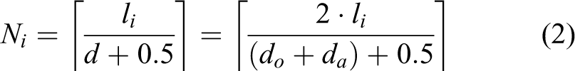
As known from formula (2), after modeling the external surface of occluded region, the total point number N on the external surface of occluded region is
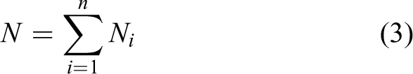
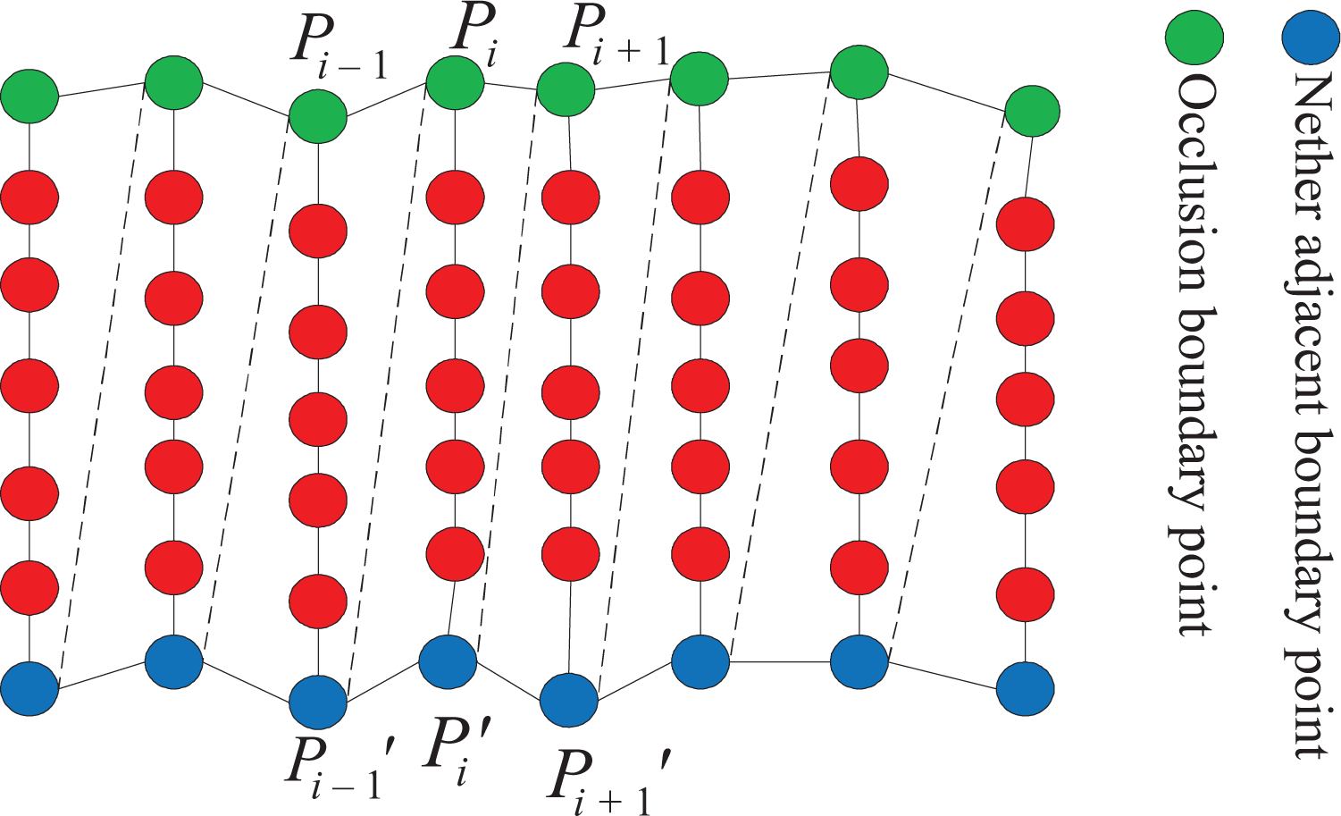
Figure 3 shows the modeling effect of some one external surface of occluded region based on the method mentioned above. In Figure 3, the green boundary is the occlusion boundary, the blue boundary is the nether adjacent boundary corresponding to the green one, and the red line segment is the occlusion straight-line segment. Meanwhile, the green point is the occlusion boundary point, the blue point is the nether adjacent boundary point, and the red point is the point on the occlusion straight-line segment.

The sketch map after modeling the external surface of occluded region.
Solving the observation direction and center point of occlusion straight-line segment on the external surface of occluded region
Calculating the observation direction of occlusion straight-line segment
For the solving observation direction of occlusion straight-line segment, it is necessary to determine the plane on which the straight-line segment locates. Take a point
The planes for the occlusion straight-line segments.
By determining the normal vectors which point to the inner of occluded region, of triangles

Similarly, the normal vector of the plane for triangle

Considering the first and the last occlusion straight-line segments correspond to the only one triangle, respectively, the normal vector which points to the inner of occluded region of the triangle can be regarded as the observation direction of this occlusion straight-line segment directly.
Calculating the observation center point of occlusion straight-line segment
The midpoint of each occlusion straight-line segment can be regarded as the observation center point of occlusion straight-line segment. Suppose

Solving the area of external surface of occluded region
In order to determine next best view, it is necessary to solve the area of each external surface of occluded region. In this article, the area of external surface of occluded region is solved based on the mass and surface density information of external surface of occluded region. The methods of calculating the mass M and surface density ρ of external surface of occluded region are given below.
Calculating the mass of external surface of occluded region
The mass of external surface of occluded region can be determined by the number and mass of all the points on the occlusion straight-line segments which belong to this external surface of occluded region. According to “Modeling the external surface of occluded region” section, we can know that the total point number of external surface of occluded region is N after modeling. Suppose m is the mass of each point on the external surface of occluded region, then the mass M of external surface of occluded region can be defined as

where n is the number of points on the occlusion boundary, namely, n is the number of occlusion straight-line segments on the external surface of occluded region, Ni is the number of points on the ith occlusion straight-line segment, li is the length of the ith occlusion straight-line segment, do is the average distance between any two neighboring occlusion boundary points, and da is the average distance between any two neighboring nether adjacent boundary points.
Calculating the surface density of external surface of occluded region
Because the external surface of occluded region is determined by the occlusion boundary and the nether adjacent boundary, the average linear density of occlusion boundary and nether adjacent boundary can be taken as the surface density ρ of external surface of occluded region. Suppose

where n is the number of occlusion boundary points on the external surface of occluded region, and m is the mass of each point on the occlusion boundary or the nether adjacent boundary, namely, m is the mass of each point on the external surface of occluded region.
Calculating the area of external surface of occluded region
Suppose M and ρ are the mass and surface density of one external surface of occluded region, then the area s of this external surface of occluded region is defined as

By substituting formulas (7) and (8) into formula (9), the formula (10) can be deduced as

Solving next best view
The “Problem description of next best view” section shows that the next best view consists of the next best observation direction and the next best observation position. In order to determine next best view, it is necessary to determine the set of candidate observation directions and the visual space of each candidate observation direction first.
Determining the sets of candidate observation directions and center points
The observation directions and the observation center points of all occlusion straight-line segments on each external surface of occluded region can be determined according to the methods mentioned in “Calculating the observation direction of occlusion straight-line segment” and “Calculating the observation center point of occlusion straight-line segment” sections. After that, the observation direction and the observation center point of each external surface of occluded region can be determined using the observation directions and the observation center points of all occlusion straight-line segments. Suppose
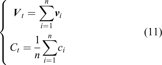
where n is the number of occlusion boundary points on the external surface of occluded region, namely, the number of occlusion straight-line segments on this external surface of occluded region.
The set of candidate observation directions Vcandidate and the set of candidate observation center points Ccandidate can be obtained by taking
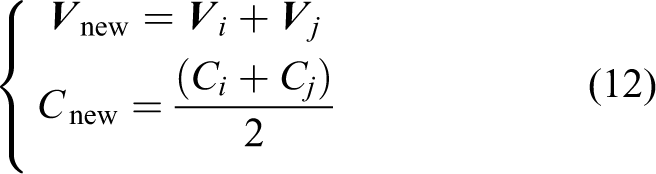
All the new obtained
Determining the visual spaces of all candidate observation directions
In this article, the visual space of each candidate observation direction in set Vcandidate is determined based on the area of each external surface of occluded region. There are two kinds of candidate observation directions in set Vcandidate. The first one is the candidate observation direction which corresponds to the external surface of occluded region directly, and the second one is the candidate observation direction which is obtained by combining the first one. The solving methods of visual space are different for these two kinds of candidate observation directions. In addition, we assumed that the whole visual object is in the field of view of camera, and the observation distances of camera are constant and enough in the process of determining the visual space of each candidate observation direction. The solving method of different visual spaces is as follow: (1) Determining the visual spaces of the first kind of candidate observation directions
Above all, a candidate observation direction

where nv is the number of the first kind of candidate observation directions in set Vcandidate, sj is the area of external surface of occluded region corresponding to
(2) Determining the visual spaces of the second kind of candidate observation directions
Similarly, a candidate observation direction

Thus, the visual spaces of all candidate observation directions in set Vcandidate can be determined according to the formulas (13) and (14).
Determining next best view
We take the candidate observation direction with the maximal visual space as the next best observation direction
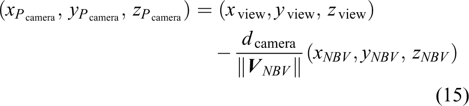
The result
Description of algorithm
Algorithm: Next best view based on occlusion information of depth image
Input: Depth image and camera internal and external parameters
Output: The next best view Step 1: Detecting the occlusion information in depth image Step 2: Constructing the external surface of occluded region according to occlusion information Step 3: Modeling the external surface of occluded region Step 4: Calculating the area of each external surface of occluded region according to formula (10) Step 5: Calculating the observation direction and center point of each external surface of occluded region according to formula (11) Step 6: Determining the sets of candidate observation directions and observation center points Step 7: Calculating the visual space of each candidate observation direction according to formulas (13) and (14) Step 8: Determining the next best observation direction and the observation position to achieve next best view
Experiment and analysis
Experimental environment and dataset
To validate the feasibility and effectiveness of proposed method, the experiment is conducted. The experimental hardware environment is CPU Pentium(R) Dual-Core 2.94 GHz, and the memory is 2.0 GB. The next best view program is implemented with C++ language. The 3D model of visual object is from the Stuttgart Range Image Database. In the process of experiment, the OpenGL is adopted to simulate the camera for observing 3D physical model and acquiring the depth image. The parameter of projection matrix in OpenGL is
Experimental results and analysis
Experimental results and analysis of proposed method
Figure 5 shows the experimental results of visual objects with different complexities. In Figure 5, the first line is the name of visual object—from left to right, they are Duck, Mole, Rocker, Bunny, and Dragon, respectively, the second line is the depth image of visual object acquired by the camera in current view, the third line is the occlusion boundary point (green pixel) and the nether adjacent boundary point (blue pixel) in the depth image of visual object, the fourth line is the observation direction of occlusion straight-line segment on the external surface of occluded region, the fifth line is the visible occlusion straight-line segment observed by the camera in next best view, and the sixth line is the depth image of visual object acquired by the camera in next best view which is calculated by proposed method in this article.

The experimental results of next best view.
As can be seen from Figure 5, for the visual object with occlusion phenomenon in current view, the proposed method can calculate the reasonable observation direction of occlusion straight-line segment according to occlusion information and then finally achieve next best view, where the camera can observe the maximal occluded region of visual object. For the visual object Duck, as the occlusion phenomenon is not obvious, the number of visible occlusion straight-line segments on the external surface of occluded region in next best view is less. But for the visual objects Mole, Rocker, Bunny, and Dragon, as the occlusion phenomenon is obvious, the number of visible occlusion straight-line segments on the external surface of occluded region in next best view is more, namely, the red region in the fifth line of Figure 5 is larger. Therefore, the more obvious the occlusion phenomenon of visual object is, the more effective the proposed method is, which is coincident with the idea of solving next best view based on occlusion information in this article. Comparing the depth images of visual object in the second line with those in the sixth line of Figure 5, we can know that the next best view obtained by the proposed method accords with the observing habit of human vision.
In the view of the fact that there is no Ground Truth about next best view currently, it is very difficult to evaluate our method by comparing its result with the Ground Truth. But in order to verify the rationality of proposed method further, we do the quantitative analysis on the experimental results in Figure 5. The analysis results are shown in Table 1. Among them, NNBV is the number of surface points of visual object obtained by the camera in next best view, NOVERLAP is the number of overlap points, NNEW is the number of new added points in next best view and
The quantitative evaluation of experimental results.
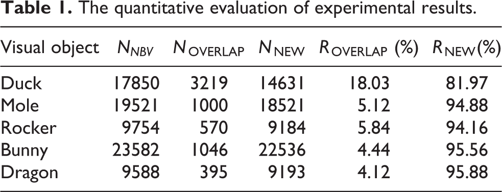
As can be seen from Table 1, there are more new added points and higher new added rate in the next best view of camera, which indicates that the camera can indeed observe the maximal unobserved region of visual object. Analyzing Figure 5 and Table 1 shows that, for the visual object Duck with fewer visible occlusion straight-line segments, its overlap rate ROVERLAP is slightly higher. The main reason is the external surface of occluded region of Duck is relatively smaller, which results in the change between next best view and current view is also smaller, thus the more observed points are observed in next best view. For the visual objects Mole, Rocker, Bunny, and Dragon with relatively more visible occlusion straight-line segments, their overlap rates ROVERLAP are lower, and new added rates RNEW are higher. It also accords with the facts that the visual objects have more occluded regions, and the external surfaces of occluded regions are larger.
Experimental result comparison and analysis of different methods
In order to evaluate the effect of proposed method better, we compare the proposed method with the methods in the studies by Banta et al. 11 and Li and Liu 12 , which are also based on the depth image and consider the occlusion information. Figure 6 shows the depth image of visual object in next best view obtained by different methods. In Figure 6, the first line is the name of visual object, the second line is the depth image of visual object in current view, the third line is the depth image of visual object in next best view obtained by the method in the study by Banta et al. 11 , the fourth line is the depth image of visual object in next best view obtained by the method in the study by Li and Liu, 12 and the fifth line is the depth image of visual object in next best view obtained by the proposed method in this article.

The depth image of visual object in next best view for different methods.
Analysis by combining Figure 6 and the principles of different methods shows that the next best view of method in the study by Banta et al. 11 focuses on observing the back of visual object in current view. The next best view obtained by the method in the study by Li and Liu 12 focuses on observing the adjoining unknown region of the largest information gain point in current view. The next best view of the proposed method in this article is based on the occluded region generated by the shape of visual object and mainly focuses on observing the unknown information of occluded region in current view, which is coincident with the original intention of determining the next best view by making full use of occlusion information.
In order to evaluate the performance of different methods further, Table 2 shows the quantitative comparison results of different methods.
The quantitative evaluation of experimental results in next best view for different methods.

Compared with the method 11 in Table 2, for the visual objects Mole, Rocker, Bunny, and Dragon, it can be seen, because the external surface of occluded region is larger and the back region is smaller, the number of new added points obtained by the proposed method is obviously more (although the new added rate is slightly lower). For the visual object Duck, because the back region of visual object is relatively larger in current view and the proposed method focuses on observing the occluded region, the number of new added points is less than that of the method in the study by Banta et al. 11 Overall, the method in the study by Banta et al. 11 focuses on observing the back of visual object, and it does not consider the occluded region generated by the shape of visual object. The proposed method makes full use of occlusion information to determine next best view, which is more beneficial to the solution of occluded region. Compared with the method in the study by Li and Liu 12 for the visual objects Mole, Rocker, Bunny, and Dragon, because the occlusion is obvious and the external surface of occluded region is larger, both the number of new added points and the new added rate are significantly better than those of the method in the study by Li and Liu. 12 For the visual object Duck with unobvious occlusion, although its number of new added points and the new added rate are relatively lower than those of visual objects Mole, Rocker, Bunny, and Dragon with obvious occlusion, the performance of proposed method is still clearly superior to that of the method in the study by Li and Liu. 12 In general, because the method in the study by Li and Liu 12 focuses on observing the adjoining unknown region of the largest information gain point in current view, the method in the study by Li and Liu 12 has higher overlap rate and the less number of new added points. The proposed method fully utilizes the occlusion information of visual object in current view to solve the candidate observation direction of external surface of occluded region and the visual space of candidate observation direction, and then determines the next best view finally. Therefore, the proposed method has a better performance for observing the occluded region of visual object.
In order to evaluate the computational complexity of different methods, Table 3 shows the time consumption of different methods, and the time consumption of each visual object is the average of 10 experiments.
The time consumption of different methods.

From Table 3, we can see that the average time consumption of the methods in the studies by Banta et al. 11 and Li and Liu 12 is 13.594 and 19.632 s, respectively, and the average time consumption of the proposed method is 2.475 s. Therefore, the average time consumption of the proposed method is less than those of the methods in the studies by Banta et al. 11 and Li and Liu. 12 This shows that not only the computational complexity of the proposed method is low but also the proposed method has better real-time.
Conclusions
A next best view approach is proposed based on the occlusion information in a single depth image. This work is distinguished by three contributions: (1) the occlusion information of visual object is taken as the focus for solving the next best view of camera, which does not acquire the prior knowledge of visual object in advance or define the camera position on a fixed surface, and then it is suitable for different types of visual objects; (2) a modeling way which divides the external surface of occluded region into sets of occlusion straight-line segments and points is proposed. This modeling way provides a feasible scheme for constructing the model of unknown occluded region based on observed information; and (3) a method for solving the area of external surface of occluded region by utilizing its mass and surface density is presented, and then the visual space of candidate observation direction and the next best view can be obtained step by step. This method provides a physics-based knowledge idea to solve the problem of next best view.
Footnotes
Declaration of conflicting interests
The author(s) declared no potential conflicts of interest with respect to the research, authorship, and/or publication of this article.
Funding
The author(s) disclosed receipt of the following financial support for the research, authorship, and/or publication of this article: This work is supported by the National Natural Science Foundation of China under grant no. 61379065 and the Natural Science Foundation of Hebei province under grant no. F2014203119.